EP0447799A2 - Wandrahmenelemente mit Befestigungselementen für Isolationsplatten - Google Patents
Wandrahmenelemente mit Befestigungselementen für Isolationsplatten Download PDFInfo
- Publication number
- EP0447799A2 EP0447799A2 EP91102087A EP91102087A EP0447799A2 EP 0447799 A2 EP0447799 A2 EP 0447799A2 EP 91102087 A EP91102087 A EP 91102087A EP 91102087 A EP91102087 A EP 91102087A EP 0447799 A2 EP0447799 A2 EP 0447799A2
- Authority
- EP
- European Patent Office
- Prior art keywords
- branch
- branches
- sheet according
- barbs
- sheet
- Prior art date
- Legal status (The legal status is an assumption and is not a legal conclusion. Google has not performed a legal analysis and makes no representation as to the accuracy of the status listed.)
- Granted
Links
Images


Classifications
-
- E—FIXED CONSTRUCTIONS
- E04—BUILDING
- E04B—GENERAL BUILDING CONSTRUCTIONS; WALLS, e.g. PARTITIONS; ROOFS; FLOORS; CEILINGS; INSULATION OR OTHER PROTECTION OF BUILDINGS
- E04B2/00—Walls, e.g. partitions, for buildings; Wall construction with regard to insulation; Connections specially adapted to walls
- E04B2/74—Removable non-load-bearing partitions; Partitions with a free upper edge
- E04B2/76—Removable non-load-bearing partitions; Partitions with a free upper edge with framework or posts of metal
- E04B2/762—Cross connections
-
- E—FIXED CONSTRUCTIONS
- E04—BUILDING
- E04B—GENERAL BUILDING CONSTRUCTIONS; WALLS, e.g. PARTITIONS; ROOFS; FLOORS; CEILINGS; INSULATION OR OTHER PROTECTION OF BUILDINGS
- E04B1/00—Constructions in general; Structures which are not restricted either to walls, e.g. partitions, or floors or ceilings or roofs
- E04B1/62—Insulation or other protection; Elements or use of specified material therefor
- E04B1/74—Heat, sound or noise insulation, absorption, or reflection; Other building methods affording favourable thermal or acoustical conditions, e.g. accumulating of heat within walls
- E04B1/76—Heat, sound or noise insulation, absorption, or reflection; Other building methods affording favourable thermal or acoustical conditions, e.g. accumulating of heat within walls specifically with respect to heat only
- E04B1/7654—Heat, sound or noise insulation, absorption, or reflection; Other building methods affording favourable thermal or acoustical conditions, e.g. accumulating of heat within walls specifically with respect to heat only comprising an insulating layer, disposed between two longitudinal supporting elements, e.g. to insulate ceilings
- E04B1/7658—Heat, sound or noise insulation, absorption, or reflection; Other building methods affording favourable thermal or acoustical conditions, e.g. accumulating of heat within walls specifically with respect to heat only comprising an insulating layer, disposed between two longitudinal supporting elements, e.g. to insulate ceilings comprising fiber insulation, e.g. as panels or loose filled fibres
- E04B1/7662—Heat, sound or noise insulation, absorption, or reflection; Other building methods affording favourable thermal or acoustical conditions, e.g. accumulating of heat within walls specifically with respect to heat only comprising an insulating layer, disposed between two longitudinal supporting elements, e.g. to insulate ceilings comprising fiber insulation, e.g. as panels or loose filled fibres comprising fiber blankets or batts
- E04B1/7666—Connection of blankets or batts to the longitudinal supporting elements
-
- E—FIXED CONSTRUCTIONS
- E04—BUILDING
- E04B—GENERAL BUILDING CONSTRUCTIONS; WALLS, e.g. PARTITIONS; ROOFS; FLOORS; CEILINGS; INSULATION OR OTHER PROTECTION OF BUILDINGS
- E04B2/00—Walls, e.g. partitions, for buildings; Wall construction with regard to insulation; Connections specially adapted to walls
- E04B2/74—Removable non-load-bearing partitions; Partitions with a free upper edge
- E04B2/7407—Removable non-load-bearing partitions; Partitions with a free upper edge assembled using frames with infill panels or coverings only; made-up of panels and a support structure incorporating posts
- E04B2/7409—Removable non-load-bearing partitions; Partitions with a free upper edge assembled using frames with infill panels or coverings only; made-up of panels and a support structure incorporating posts special measures for sound or thermal insulation, including fire protection
- E04B2/7414—Posts or frame members with projections for holding sound or heat insulating fillings
-
- Y—GENERAL TAGGING OF NEW TECHNOLOGICAL DEVELOPMENTS; GENERAL TAGGING OF CROSS-SECTIONAL TECHNOLOGIES SPANNING OVER SEVERAL SECTIONS OF THE IPC; TECHNICAL SUBJECTS COVERED BY FORMER USPC CROSS-REFERENCE ART COLLECTIONS [XRACs] AND DIGESTS
- Y10—TECHNICAL SUBJECTS COVERED BY FORMER USPC
- Y10S—TECHNICAL SUBJECTS COVERED BY FORMER USPC CROSS-REFERENCE ART COLLECTIONS [XRACs] AND DIGESTS
- Y10S52/00—Static structures, e.g. buildings
- Y10S52/06—Toothed connecting means
Definitions
- the invention relates to hollow wall reinforcement elements comprising insulating panel anchors, in particular to prevent the collapse of these panels over time.
- the retention zone of the branch to the amount can yield under the effect of a second folding .
- Another problem of the patented amount relates to the degree of folding to immobilize the branch to its optimum position of anchoring the glass wool.
- the main purpose of the invention is therefore to provide a wall frame amount in which each branch can be folded only in one direction, the branches can be folded alternately on either side of the amount.
- Another object of the invention is to provide simple means for stopping the folding of the branches in an operative limit position perpendicular to the upright, which is the optimum position for the impalement and anchoring of the insulating panels.
- Another object of the invention relates to plates and beams for wall frames which are provided with branches having the above characteristics.
- hollow wall frame elements provided with means for retaining compressible insulating panels against sagging within a wall.
- These elements include more particularly amounts and plates.
- These elements are made of sheet metal and are provided with branches made by stamping in a flat portion of the sheet and leaving an opening of the same shape.
- Each branch is of elongate shape with a sharp open end, barbs projecting from at least one of the sides of the branch and the latter having an integral inner end to said sheet portion along a fold line transverse to the branch, the branch being foldable into an operative position generally perpendicular to said sheet portion and to one side thereof from an inoperative position generally parallel to said sheet portion.
- a first feature of the invention consists in the fact that each branch, in its position inoperative, protrudes slightly from one of the two opposite faces of said sheet portion and to a portion which overhangs the edge of said opening, so that the branch can not be bent through said opening, because this portion then abuts against the edge of it.
- each branch comprises, in the vicinity of its fold line, an abutment projecting from said first face and which engages against said sheet portion in the operating position of the branch.
- the branches are arranged in spaced pairs along the upright and the branches of each pair are close to each other, and in their inoperative position, protrude from opposite sides of the upright soul. to be folded only in opposite directions on both sides of the upright, so as to impale the insulating panels at regular intervals along the upright and on each side thereof.
- the invention also includes plates provided with the aforementioned branches and which can be attached to wall frame amounts which are wood or sheet metal. These plates can be installed on studs already in place, which requires the removal of plasterboard panels on one side of the wall.
- the invention also provides for branches provided with barbs on each side and which can be used to impale the insulating panel that is presented to him from any side of the wall.
- the invention also comprises rigid insulating panels retaining beams and provided with branches according to the invention.
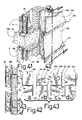
- the wall M comprises a frame or rigid frame made of sheet metal elements. These elements include spaced studs, indicated at 22, whose bottom end is inserted into and attached to a joister 23, which is secured to the ground S and whose upper end, not shown, is inserted into and attached to a ceiling joist. , not shown.
- the uprights 22 may be solidified by U-shaped beams 23A, which pass through appropriate square-shaped openings of a series of uprights 22. These uprights are also provided with circular holes for the passage of conduits 23B for electrical wires or for plumbing.
- Each upright 22 has a U-shaped profile which comprises a core 22a and two flanges 22b and 22c.
- Each post 22 is provided with a series of pairs of branches 24 and 26, which in their operative position are folded at right angles to the web 22a and each side of this soul, and serve to impale and retain insulating panels, flexible and compressible, indicated at 28, specifically fiberglass sheets, which are installed in the space between two successive amounts.
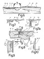
- Each of the branches 24 and 26, according to FIGS. 1 to 10, is obtained by partial cutting of the core 22a of the amount 22 by means of a matrix and a punch.
- Each branch has the shape of an elongated finger, of generally rectangular shape, with two free longitudinal edges 32, 34, a free outer point 36 and an inner end 38 integrally retained by the core 22a.
- the branch 24 or 26 is in a position almost parallel to the core 22a.
- the branch 24, as shown in Figure 6 projects from the inner face of the core 22a, that is to say the face which is exposed between the tabs or flanges 22b and 22c, while the branch 26 protrudes from the outer face of the soul 22a.
- Each leg 24, 26 can be bent from its inoperative position indicated above to an operative position at right angles to the core 22a, as shown, for example, in FIGS. 2, 7a and 8.
- branch is pivoted to its operative position along the fold line, indicated in B in Figure 5, which corresponds approximately to the inner ends of the cutout which formed the longitudinal edges 32 and 34.
- Cutting branches 24 and 26 result in the formation of openings 40, of the same shape, in the core 22a.
- the longitudinal edge 32 is straight, while the opposite edge 34 has several barbs 42. Each barb defines a straight edge 42a facing away from the tip 36. This tip promotes the impaction of the insulating panel 28.
- Each branch 24 and 26 is provided with a reinforcing rib, longitudinal and central 44 which protrudes from the branch on the side of the inner face of the core 22a, while each branch 26 is provided with a similar rib 46, which protrudes from the side of the outer face of the core 22a, as clearly shown in Figure 6.
- the inner ends of the ribs 44 and 46 are in the vicinity of the fold line B, which is located in a flat part of the soul 22a.
- a boss 48 or 49 is formed in the core 22a in alignment with the ends of the ribs 44, 46 respectively and on the same side as these ribs with respect to the plane of the core. 22a. More particularly, the boss 48 protrudes on the same side as the rib 44, while the boss 49, associated with the branch 26, protrudes on the same side as the rib 46.
- the punch and the die used to cutting the branch 24 act opposite to the punch and die used to cut the branch 26.
- the ribs 44 and 46 act together with the stops 48 and 49 to engage each other in the operative position of the branch, that is to say in the position in which the branch is 90 degrees to the core 22a, as shown in Figure 7a.
- means are provided to prevent the leg 24 or 26 from being pivoted along the fold line B in a direction which passes the branch through the opening 40 made in the soul 22a.
- the metal in the region 38 and the fold line B is stretched unevenly transversely to the branch, so it, once cut, moves longitudinally and also laterally of an angle indicated in alpha, so that the edge of the branch become vis-à-vis and interfere with the corresponding edges of the opening 40.
- the branches 24 and 26 are as in the patent aforementioned American, namely the branches are arranged in spaced pairs along the amount, the branches of each pair are close to each other, the longitudinal axis of each branch is inclined in the same direction relative to the longitudinal axis of the upright 22 and also the fold line B is inclined relative to the longitudinal axis of the branch 24 or 26, the barbs 42 of the branches are arranged on the same side thereof.
- each branch takes a double inclination with respect to the amount.
- a first inclination as shown particularly in Figure 8, wherein each branch is inclined to the flange 22b in a plane perpendicular to the plane of the core 22a; and a second inclination, as shown in FIG. 9, according to which each branch, in its transverse direction, is inclined with respect to the longitudinal axis of the upright 22.
- stops 44, 48 and 46,49 which maintain the branches at right angles to the core 22a and, therefore, in a horizontal position, that these branches can not tilt downward with the time under the weight of fiberglass sheets 28.
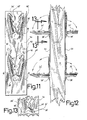
- FIGS. 11 and 13 show a rectangular plate 54, provided with holes 52, for fastening this plate by means of nails or the like to each of the two opposite faces of a wooden post D (FIG. 12) or to each opposite face of the 22a soul of a metal upright 22 when the amount is made of a sheet thicker than normal and does not allow the tool-free folding of the branches in the core of the sheet.
- the plate 54 is provided with two pairs of branches 24 ', 26'.
- the branches 24 'and 26' of each pair are at the same level and are diverging towards their pointed ends. It is only their inner longitudinal edges which are provided with barbs 42 ', similar to the barbs 42, and which face each other in their inoperative position.
- Each branch 26 ' is provided with a rib 46 ', whose inner end is in the vicinity of the fold line B while on the other side of the fold line, a boss 38' serving as a stop, is common to the two branches 24 ', 26. In their inoperative position, all the branches 24 ', 26' protrude slightly from the outer face of the plate 54. Likewise, the bosses 38 'and the ribs 46' project from the outside face of the plate 54. to place the plate against the opposite faces of the upright D with the pointed ends of the branches 26 'pointing upwards and that the plates are applied with the branches 26' outside the upright.
- branches 24 'and 26' of each pair whose barbs 42 'are going to be oriented towards the installer and inclined upwards in the same direction we choose to unfold that of the branches 24 'and 26' of each pair whose barbs 42 'are going to be oriented towards the installer and inclined upwards in the same direction, as has been written in connection with the figures 8 and 9.
- the branches can only be bent in the outer direction to the plate, since the branches are offset laterally and also longitudinally with respect to the holes 40 'formed in the plate by the stamping of the branches.
- the branches are positively maintained in their operative position at right angles to the plate 54.
- FIGS. 14 to 19 show a plate 54 'which is installed in the same manner as the plate 54, either on the opposite sides of a wooden post D, or on opposite sides of the core of a conventional post in jail.
- Plate 54 ' has holes 52 for attachment.
- the branches 26 'of each pair are replaced by a single branch 56, each of whose two longitudinal edges is provided with a series of barbs 58a, 58b and which is also provided with a central and longitudinal reinforcing rib, indicated in FIG. 59, whose inner end is in the vicinity of the fold line B '.
- the sheet of plate 54 ' forms a boss 38 "on the other side of the fold line
- the width of branch 56 decreases in the direction of fold line B', except for the end pointed end of the branch 56. This pointed end is provided with a bulging extension, indicated at 60, which overlaps by an OS value the corresponding edge of the opening 40 ", which resulted from the cutting of the branch 56.
- the extension 60 thus prevents the branch from being pivoted through the opening 40 ".
- the lateral edges of the branch and the barbs 58a and 58b are diverging and inclined with respect to the plate 54 'In the inoperative position of the branch 56, the barbs extend through the opening 40 ", as shown in FIG. 15.
- the branch 56 In its operative position, shown in FIGS. 16 and 17, the branch 56 is held in its horizontal position at right angles to to the plate 54 'by the boss 38 "and the inner end of the rib 59.
- the plate 54 it is not necessary to choose which of the plasterboard panels P must be installed last because there is always a series of barbs that face the installer, as in Figure 8.
- the barbs are angled upward towards the installer, as in Figure 8, and also the decrease of the width of the branch makes the barbs inclined to the installer in a plane perpendicular to the plane of the plate 54 'as the barbs of the branches 24, 26 in Figure 8.
- the branches 56 fold all on the same side to protrude from the outer face of the plate 54 'in their operative position.
- branches 54 ' are arranged in pairs with the branches of the same pair in the vicinity of one another, and the branches of the same pair can rotate only in oposed directions, ( Figure 21) and are maintained angled right with respect to the core of the upright by means of the reinforcement ribs of the branches as well as the bosses 38 ", just as in the plate of FIG. 14.
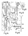
- Figures 22 to 27 show a metal upright 62 provided with groups of two pairs of legs which are spaced along the upright.
- the branches of the first pair are indicated at 64 and 64a and the branches of the second pair are indicated at 66 and 66a.
- the branches of each pair are arranged similarly to the branches 26 'of FIG. 11.
- the branches 64, 64a fold only towards the inside of the upright 62 while the branches 66, 66a fold only towards the outside of the upright 62.
- the branches of the same pair are arranged at the same level along the upright 62. They are diverging towards their sharp free ends 68 and their inner ends can be folded along the respective fold lines B ".
- the same pair has a series of barbs 70 along the inner side, which face the other branch of the same pair.
- the branches are shifted laterally when they are cut, so that the edge of the opening 72, which results from the cutting of the branch in the core 62a, makes interference with the corresponding branch.
- the branches 66, 64a project into their inoperative position of the outer face of the soul 62a, while the branches 64, 64a project from the inner face of the same soul 62a.
- the reinforcing ribs 74 of the branches 64, 64a are set back from the outer face of the core 62a, while the reinforcement ribs 76 of the branches 66, 66a are in relief.
- the two superposed branches 64, 66 are folded into their operative position, so that the barbs 70 are facing towards each other. the installer and that the branches are also inclined laterally towards the installer, as in Figure 8. If one wants to install the fiberglass panels in the opposite direction, as shown by the arrows 80, one folds then the pair of branches 64a and 66a, as shown in Figure 24.
- the reinforcing rib 74 or 76 extends along the central axis of the limb and its inner end 82 is completely broken down to leave a hole 84 at This constitutes an abutment for holding the branch in operative position at 90 degrees with respect to the core 62a, as shown in Fig. 27. In this case, it is not necessary to have a boss on the part of the soul beyond the fold line B ".
- Figures 28 and 29 show a plate 86, which is similar to that of Figure 11 and serves the same purpose. It is provided at two different levels of pairs of branches 88 which are similar to the branches 26 'of FIG. 11, with the exception of the stop means for keeping them at 90 degrees from the plate in their operative position, these means consisting of by ribs 76a protruding outwardly of the plate and whose inner end, which defines a hole 84, abuts against the plate 86 in the operative position of the branch at right angles to the plate.
- Figures 30 and 31 show a branch 90 provided with a stop 92 which terminates at the fold line B ", as for the branches 88 of Figure 28, but which is much shorter than the reinforcing rib 76a and that is bumped at both ends
- the stop 92 is used when the sheet is thick enough not to require reinforcing ribs in the branch 90.
- Such a stop 92 comes directly against the plate against the plate 62a or 86 in the operative position of the branch, as shown in Figure 31.
- a such branch 90 can be used not only for the plates but also for the souls of the metal uprights.
- FIG. 32 shows a plate 94 provided with branches 96, arranged in divergent pairs, as in the plate 54 of FIG. 11.
- This plate 94 serves the same purpose as the plate 54.
- Each branch is offset laterally so that they are prevented. to pass through the opening 98 in the plate.
- Each branch 96 is provided with an abutment 100 identical to the abutment 92 of FIG. 29.
- the branches 96 bend along the fold line B ".
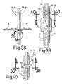
- the plate 94 is characterized by the fact that it is provided with two hooks 102 arranged along the center line of the plate 94. These hooks are folded towards the inner face of the plate 94 and are partially cut in an opening 104 formed in the plate during the stamping of the hooks 102.
- Each hook has a tab 106, whose height is equal to 1.3 times the distance J between the free bottom end 108 of the tab 106 and the lower edge 110 of the opening 104.
- the upper edge 112 of the opening 104 is equal at the height of the tab 106, that is to say 1.3 times J.
- a metal upright 114 of conventional construction and illustrated in FIG. 35, is characterized by the fact that its core 116 is provided with pairs of rectangular holes 118 arranged along the center line of the core 116 at a distance one from the other, indicated by Y, which is equal to the distance between the hooks 102 of the plate 94.
- These holes 118 are of rectangular shape, and as shown in FIG. 36, their width is approximately equal to 2.2 times the thickness T of the plate 94, while the height of the holes 118 is equal to about 1.2 times the total height C of the hook 102.
- two plates 94 provided with their hooks 102, can be mounted back-to-back on each side of the core 116 with the hooks 102 inserted one beside the other in the opening 118 and in the opening 104 of the other plate 94 and clinging in the opening 118, as shown in Figures 39 and 40.
- the height of these openings is sufficient for one to return the whole hook with its paw in an elevated position and then let down the plate so that the tab of the hook comes abut against the opposite face of the core 116 of the upright 114.
- FIG. 37 shows a conventional upright 119 of sheet metal and the like 114, but the openings 118 of which are replaced by conventional holes 120, which can be made on site or made at the factory to fix them with metal screws.
- plates such as the plates 54 of Figure 11 in opposite positions on each side of the upright core.
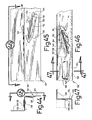
- FIGS. 41 to 46 show a wall reinforcement element, indicated at 122, which constitutes a beam intended to be placed horizontally and of Z profile, namely a folded sheet to form a central core 124 and two flanges 126, 128 at right angles directed in opposite directions.
- the core 124 and the flange 126 are provided, at uniform distances along the beam, branches 130 and 132 respectively.
- the branches 130 which are obtained by cutting in the flange 126, are very similar to the branches 24, 26 of Figures 1 to 11. They have barbs 134 only one longitudinal side.
- the branches 132, which are cut in the core 124, are similar to the branches 132, except that they are provided with barbs 136 on both sides of the branch.
- the branches 130, 132 are offset laterally and longitudinally during stamping so as to interfere with the periphery of the opening formed by their stamping.
- the branches 130, 132 can only be folded on one side of the web or flange.
- the branches 132, made in the core 124 they can only be folded in the operative position in the opposite direction to a boss 138 made in the core 124 by cutting and which forms a ridge 140 facing the rim 126 provided with branches 130.
- Each branch 130, 132 is provided with a longitudinal central rib 142, 144, whose inner end 146, 148 abuts against a boss 150, 152 in the operative position of the branch, so as to retain this in a plane perpendicular to the core 124 and the flange 126 respectively.
- FIG. 41 and 42 show the use of the beam 122. It serves to retain in place rigid insulation panels, indicated 154, which are used for the facade walls of a building. These rigid panels are generally made of polyurethane foam or compressed glass fibers. Insulating panels 28 made of uncompressed glass fibers, and therefore flexible and compressible panels are also shown in FIG. 41; they are arranged between the uprights 22. The interior side of the façade wall alone is completed by the plasterboard panels P.
- Figure 41 shows a concrete floor 156 of a building with posts 22 inserted in a joists 23 fixed to the floor and ceiling truss 160.
- the outer edge of the concrete floor 156 and the outer side of the hollow wall are closed by rigid insulating panels 162, on which are fixed the horizontal beams 122.
- the vertical distance between the various beams 122 is equivalent to the height of the panels 154, which are standard dimensions.
- the flange 126 provided with the branches 130, is directed upwards and applied directly against the panels 162.
- the panel 154 is placed from the outside of the front wall first by inserting the upper edge of the panel 154 between the flange 128 and the panel 162 and lifting the panel according to the arrow 164 so that it is impaled by the branches 132 with double barbs. The lower edge of the panel is then simply pushed against the branches 130 of the flange 126 along the arrow 166 and the lower flange of the panel becomes hung not only by the barbs 134 but also by the edge 140 of the boss 138.
- the beams 122 may be installed in the position shown in Figure 43-c. In this position, the beam was rotated 180 degrees clockwise from the position of Figure 43-b.
- the panels 154 are also installed from the outside of the front wall but by first inserting the lower edge of the panel in the underlying beam according to the arrow 168 so that this lower edge is impaled by the branches to double barbs 132 and then the upper edge of the panel is pushed against the branches 130 in the direction of the arrow 166.
- the same beams 122 may be fixed in one or the other of the positions of FIGS. 43-a or 43-d for installation of the panels 154 from inside the building, according to the arrows 170.
- FIG. 43-a begins by impregnating the lower edge of the panel 154 according to the arrow 168, while in the position 43-d, the impediment is first impinged on the upper edge of the panel according to the arrow 164.
Landscapes
- Architecture (AREA)
- Engineering & Computer Science (AREA)
- Physics & Mathematics (AREA)
- Structural Engineering (AREA)
- Electromagnetism (AREA)
- Civil Engineering (AREA)
- Acoustics & Sound (AREA)
- Building Environments (AREA)
- Load-Bearing And Curtain Walls (AREA)
- Panels For Use In Building Construction (AREA)
- Joining Of Building Structures In Genera (AREA)
- Finishing Walls (AREA)
- Filling Or Discharging Of Gas Storage Vessels (AREA)
Applications Claiming Priority (2)
| Application Number | Priority Date | Filing Date | Title |
|---|---|---|---|
| CA002010500A CA2010500C (fr) | 1990-02-20 | 1990-02-20 | Montant de cadres de mur avec fourches d'ancrage de panneau isolant |
| CA2010500 | 1990-02-20 |
Publications (3)
| Publication Number | Publication Date |
|---|---|
| EP0447799A2 true EP0447799A2 (de) | 1991-09-25 |
| EP0447799A3 EP0447799A3 (en) | 1991-10-09 |
| EP0447799B1 EP0447799B1 (de) | 1994-12-07 |
Family
ID=4144346
Family Applications (1)
| Application Number | Title | Priority Date | Filing Date |
|---|---|---|---|
| EP91102087A Expired - Lifetime EP0447799B1 (de) | 1990-02-20 | 1991-02-14 | Wandrahmenelemente mit Befestigungselementen für Isolationsplatten |
Country Status (7)
| Country | Link |
|---|---|
| US (1) | US5060441A (de) |
| EP (1) | EP0447799B1 (de) |
| JP (1) | JPH04250244A (de) |
| AT (1) | ATE115220T1 (de) |
| AU (1) | AU7119691A (de) |
| CA (1) | CA2010500C (de) |
| DE (1) | DE69105563D1 (de) |
Cited By (1)
| Publication number | Priority date | Publication date | Assignee | Title |
|---|---|---|---|---|
| EP1793057A3 (de) * | 2005-12-05 | 2009-08-26 | Protektorwerk Florenz Maisch GmbH & Co. KG | Aufdopplungsprofil zur Erhöhung der Höhe eines Trägers |
Families Citing this family (21)
| Publication number | Priority date | Publication date | Assignee | Title |
|---|---|---|---|---|
| US5299403A (en) * | 1992-04-17 | 1994-04-05 | Lissco Products, Inc. | Insulation fastener |
| AU4005597A (en) | 1996-08-19 | 1998-03-06 | Les Bois Laumar Inc. | Steel-wood system |
| CA2192427C (en) * | 1996-08-19 | 2001-07-31 | Marcel Leblanc | Steel-wood system |
| US6199336B1 (en) | 1999-03-11 | 2001-03-13 | California Expanded Metal Products Company | Metal wall framework and clip |
| US6634148B2 (en) | 2001-11-29 | 2003-10-21 | Edward C. Shidler | Insulated poured wall system |
| DE202005011211U1 (de) * | 2004-09-07 | 2005-12-29 | Deutsche Rockwool Mineralwoll Gmbh + Co Ohg | Vorrichtung zur Befestigung von Dämmstoffelementen auf einer Dachunterkonstruktion und Gebäudedach |
| DE102005031790A1 (de) * | 2004-09-07 | 2006-03-30 | Deutsche Rockwool Mineralwoll Gmbh + Co Ohg | Vorrichtung zur Befestigung von Dämmstoffelementen auf einer Dachunterkonstruktion und Gebäudedach |
| US20120151869A1 (en) * | 2010-12-20 | 2012-06-21 | United States Gypsum Company | Insulated drywall ceiling on steel "c" joists |
| US8621798B2 (en) | 2010-12-27 | 2014-01-07 | Lionel E. Dayton | Construction insulating panel |
| NZ718331A (en) | 2012-05-11 | 2016-12-23 | Derek Barr Owen | Panel frame assembly |
| US8844230B2 (en) * | 2012-09-14 | 2014-09-30 | Daniel J. Harkins | Building insulation system |
| US9441371B1 (en) * | 2012-09-14 | 2016-09-13 | Daniel J. Harkins | Building insulation system |
| US9163411B2 (en) | 2012-11-01 | 2015-10-20 | Todd A. Brady | Exterior wall assembly systems |
| US10309100B2 (en) | 2016-12-09 | 2019-06-04 | Owens Corning Intellectual Capital, Llc | Mullion cover hanger and curtain wall insulation system incorporating the same |
| US10370846B1 (en) | 2017-02-08 | 2019-08-06 | George M. Neuwirt | Framed wall insulation backing device, and related systems and methods |
| US11078664B1 (en) * | 2018-12-05 | 2021-08-03 | Altenloh, Brinck & Co. Us, Inc. | Apparatuses for mounting and supporting insulation |
| US11060278B2 (en) * | 2019-02-07 | 2021-07-13 | Kenneth Huber | Precursors for impaling clips and impaling clips formed therefrom for mounting acoustic panels onto structural components |
| US12209405B2 (en) * | 2020-04-29 | 2025-01-28 | Owens Corning Intellectual Capital, Llc | Insulation mounting bracket |
| CN112459300A (zh) * | 2020-11-27 | 2021-03-09 | 中冶建工集团有限公司 | 一种新型吸音隔墙的施工方法 |
| AU2021415904A1 (en) | 2020-12-31 | 2023-06-29 | Owens Corning Intellectual Capital, Llc | Curtain wall insulation system |
| US12331510B2 (en) * | 2022-06-10 | 2025-06-17 | John William Thomas Sherman | Wall cladding panels, systems, and methods of installation and use |
Family Cites Families (14)
| Publication number | Priority date | Publication date | Assignee | Title |
|---|---|---|---|---|
| US1412186A (en) * | 1920-12-15 | 1922-04-11 | Charles V Limerick | Lock tack |
| US2047386A (en) * | 1935-03-25 | 1936-07-14 | Foundry Equipment Company | Wall panel |
| US3196499A (en) * | 1962-05-21 | 1965-07-27 | Dow Chemical Co | Sandwich panel fasteners |
| DE1459885A1 (de) * | 1963-01-10 | 1969-05-08 | Automated Building Components | Metallisches Anschlussstueck zum Verbinden von hoelzernen Strukturgliedern und unter Verwendung eines solchen Stuecks hergestellte Verbindung |
| DE1258679B (de) * | 1965-10-02 | 1968-01-11 | Ego Elektro Blanc & Fischer | Befestigungsvorrichtung fuer einen Rohrheizkoerper in einer Behaelterwandoeffnung |
| SU541001A1 (ru) * | 1973-12-27 | 1976-12-30 | Центральный научно-исследовательский и проектно-экспериментальный институт промышленных зданий и сооружений | Стена |
| DE2650181C3 (de) * | 1976-02-19 | 1980-04-17 | Greimbau-Lizenz-Gmbh, 3200 Hildesheim | Krallenplatte |
| DE2613522C3 (de) * | 1976-03-30 | 1979-05-23 | Greimbau-Lizenz-Gmbh, 3200 Hildesheim | Für Holzverbindungen bestimmte Krallenplatte |
| DE3000975A1 (de) * | 1980-01-12 | 1981-07-23 | Reinhard 2970 Emden Docter | Wind- und regenschutz fuer zweiradfahrzeuge |
| US4512130A (en) * | 1982-03-22 | 1985-04-23 | Pepin Jean P | Insulation support |
| DE3231487A1 (de) * | 1982-08-25 | 1984-03-01 | Richter-System GmbH & Co KG, 6103 Griesheim | Staenderprofil fuer zweischalige waende |
| US4710083A (en) * | 1984-10-29 | 1987-12-01 | Johann Wolf Gesellschaft M.B.H. Kg | Nailing plate for the production of compound supports, and compound support |
| US4761928A (en) * | 1987-07-06 | 1988-08-09 | Carold Pichette | Insulating batts sag preventing wall frame stud |
| CA1324718C (fr) * | 1987-07-06 | 1993-11-30 | Carold Pichette & Fils Ltee | Montant de cadre de mur pour prevenir l'affaissement des panneaux isolants de ce mur |
-
1990
- 1990-02-20 CA CA002010500A patent/CA2010500C/fr not_active Expired - Fee Related
-
1991
- 1991-02-14 EP EP91102087A patent/EP0447799B1/de not_active Expired - Lifetime
- 1991-02-14 US US07/655,052 patent/US5060441A/en not_active Expired - Fee Related
- 1991-02-14 AT AT91102087T patent/ATE115220T1/de not_active IP Right Cessation
- 1991-02-14 DE DE69105563T patent/DE69105563D1/de not_active Expired - Lifetime
- 1991-02-19 AU AU71196/91A patent/AU7119691A/en not_active Abandoned
- 1991-02-20 JP JP3109903A patent/JPH04250244A/ja active Pending
Cited By (1)
| Publication number | Priority date | Publication date | Assignee | Title |
|---|---|---|---|---|
| EP1793057A3 (de) * | 2005-12-05 | 2009-08-26 | Protektorwerk Florenz Maisch GmbH & Co. KG | Aufdopplungsprofil zur Erhöhung der Höhe eines Trägers |
Also Published As
| Publication number | Publication date |
|---|---|
| DE69105563D1 (de) | 1995-01-19 |
| AU7119691A (en) | 1991-08-22 |
| EP0447799B1 (de) | 1994-12-07 |
| ATE115220T1 (de) | 1994-12-15 |
| EP0447799A3 (en) | 1991-10-09 |
| CA2010500A1 (fr) | 1991-08-20 |
| CA2010500C (fr) | 2000-01-25 |
| JPH04250244A (ja) | 1992-09-07 |
| US5060441A (en) | 1991-10-29 |
Similar Documents
| Publication | Publication Date | Title |
|---|---|---|
| EP0447799B1 (de) | Wandrahmenelemente mit Befestigungselementen für Isolationsplatten | |
| CA1234701A (fr) | Systeme constructif utilisant des coffrages perdus | |
| CH625009A5 (en) | Assembly allowing the hanging of a construction panel | |
| CA2398882A1 (fr) | Profile de structure, notamment pour cloisons | |
| CA2983952A1 (fr) | Panneau structural modulaire et ensemble comportant de tels panneaux pour la construction d'un batiment | |
| EP0285465B1 (de) | Bauelement, insbesondere Verkleidungselement mit integrierter Wärmedämmung | |
| FR2547848A1 (fr) | Paroi prefabriquee destinee a la construction de maisons et autres batiments, et son procede de fabrication | |
| EP0874942B1 (de) | Rohbausystem zur herstellung von gebäuden, insbesondere einfamilienhäuser | |
| CA2036275A1 (fr) | Elements d'armature de mur avec branches d'ancrage de panneaux isolants | |
| FR2725350A1 (fr) | Perfectionnements aux moyens en vue de la realisation d'un rayonnage et rayonnages realises a l'aide de ces moyens | |
| FR2497253A1 (fr) | Fixation de panneaux de construction | |
| EP3901387B1 (de) | Verfahren zur herstellung und zum einbau einer abgehängten decke aus vertikalen lamellen | |
| FR2539442A1 (fr) | Piece de liaison pour elements d'ossature | |
| EP0298838B1 (de) | Mauerrahmenpfosten zum Vermeiden eines Zusammenbruchs der Wärmedämmungspaneele dieser Mauer | |
| EP0288326A1 (de) | Verfahren zum Verlegen von rechteckigen Platten auf einer Fassade sowie Klammer mit Haken zur Durchführung dieses Verfahrens | |
| FR2605340A1 (fr) | Systeme constructif modulaire en bois, industrialisable et mis en oeuvre a l'aide d'un seul outil, systeme applicable au domaine de l'architecture. | |
| FR2764917A1 (fr) | Ossature secondaire destinee a supporter un bardage rapporte sur la structure porteuse d'une facade et facade comportant une ossature secondaire et des panneaux de bardage | |
| FR2590303A1 (fr) | Perfectionnements aux plafonds a ecrans | |
| LU85722A1 (fr) | Fixation de feutres ou panneaux d'isolation | |
| FR2585751A1 (fr) | Coffrage de bord de plafond | |
| BE847979A (fr) | Dispositif pour reperer des niveaux et des aplombs. | |
| FR2552471A1 (fr) | Element de paroi porteuse ou non porteuse monobloc pour batiment | |
| EP0701646B1 (de) | Profil für ein sandwichförmiges wandtragendes paneel, paneel mit einem solchen profil und konstruktion mit einem solchen paneel | |
| FR2608196A1 (fr) | Coffrages perdus en elements metalliques pliables | |
| BE1007969A6 (fr) | I.h.s. (international housing system). |
Legal Events
| Date | Code | Title | Description |
|---|---|---|---|
| PUAI | Public reference made under article 153(3) epc to a published international application that has entered the european phase |
Free format text: ORIGINAL CODE: 0009012 |
|
| PUAL | Search report despatched |
Free format text: ORIGINAL CODE: 0009013 |
|
| AK | Designated contracting states |
Kind code of ref document: A2 Designated state(s): AT BE CH DE DK ES FR GB GR IT LI LU NL SE |
|
| AK | Designated contracting states |
Kind code of ref document: A3 Designated state(s): AT BE CH DE DK ES FR GB GR IT LI LU NL SE |
|
| 17P | Request for examination filed |
Effective date: 19920327 |
|
| 17Q | First examination report despatched |
Effective date: 19921230 |
|
| GRAA | (expected) grant |
Free format text: ORIGINAL CODE: 0009210 |
|
| AK | Designated contracting states |
Kind code of ref document: B1 Designated state(s): AT BE CH DE DK ES FR GB GR IT LI LU NL SE |
|
| PG25 | Lapsed in a contracting state [announced via postgrant information from national office to epo] |
Ref country code: IT Free format text: LAPSE BECAUSE OF FAILURE TO SUBMIT A TRANSLATION OF THE DESCRIPTION OR TO PAY THE FEE WITHIN THE PRE;WARNING: LAPSES OF ITALIAN PATENTS WITH EFFECTIVE DATE BEFORE 2007 MAY HAVE OCCURRED AT ANY TIME BEFORE 2007. THE CORRECT EFFECTIVE DATE MAY BE DIFFERENT FROM THE ONE RECORDED.SCRIBED TIME-LIMIT Effective date: 19941207 Ref country code: DK Effective date: 19941207 Ref country code: GB Effective date: 19941207 Ref country code: NL Effective date: 19941207 Ref country code: GR Free format text: LAPSE BECAUSE OF FAILURE TO SUBMIT A TRANSLATION OF THE DESCRIPTION OR TO PAY THE FEE WITHIN THE PRESCRIBED TIME-LIMIT Effective date: 19941207 Ref country code: ES Free format text: THE PATENT HAS BEEN ANNULLED BY A DECISION OF A NATIONAL AUTHORITY Effective date: 19941207 Ref country code: AT Effective date: 19941207 |
|
| REF | Corresponds to: |
Ref document number: 115220 Country of ref document: AT Date of ref document: 19941215 Kind code of ref document: T |
|
| REF | Corresponds to: |
Ref document number: 69105563 Country of ref document: DE Date of ref document: 19950119 |
|
| PG25 | Lapsed in a contracting state [announced via postgrant information from national office to epo] |
Ref country code: LI Effective date: 19950228 Ref country code: CH Effective date: 19950228 |
|
| PG25 | Lapsed in a contracting state [announced via postgrant information from national office to epo] |
Ref country code: SE Effective date: 19950307 |
|
| PG25 | Lapsed in a contracting state [announced via postgrant information from national office to epo] |
Ref country code: DE Effective date: 19950308 |
|
| NLV1 | Nl: lapsed or annulled due to failure to fulfill the requirements of art. 29p and 29m of the patents act | ||
| REG | Reference to a national code |
Ref country code: GB Ref legal event code: 777B |
|
| PLBE | No opposition filed within time limit |
Free format text: ORIGINAL CODE: 0009261 |
|
| STAA | Information on the status of an ep patent application or granted ep patent |
Free format text: STATUS: NO OPPOSITION FILED WITHIN TIME LIMIT |
|
| REG | Reference to a national code |
Ref country code: GB Ref legal event code: 710A Ref country code: GB Ref legal event code: 710B |
|
| 26N | No opposition filed | ||
| REG | Reference to a national code |
Ref country code: FR Ref legal event code: ST |
|
| REG | Reference to a national code |
Ref country code: FR Ref legal event code: RN |
|
| REG | Reference to a national code |
Ref country code: FR Ref legal event code: FC |
|
| PGFP | Annual fee paid to national office [announced via postgrant information from national office to epo] |
Ref country code: FR Payment date: 19990823 Year of fee payment: 9 |
|
| PGFP | Annual fee paid to national office [announced via postgrant information from national office to epo] |
Ref country code: LU Payment date: 19990826 Year of fee payment: 9 |
|
| PGFP | Annual fee paid to national office [announced via postgrant information from national office to epo] |
Ref country code: BE Payment date: 19990831 Year of fee payment: 9 |
|
| PG25 | Lapsed in a contracting state [announced via postgrant information from national office to epo] |
Ref country code: LU Free format text: LAPSE BECAUSE OF NON-PAYMENT OF DUE FEES Effective date: 20000214 |
|
| PG25 | Lapsed in a contracting state [announced via postgrant information from national office to epo] |
Ref country code: BE Free format text: LAPSE BECAUSE OF NON-PAYMENT OF DUE FEES Effective date: 20000228 |
|
| BERE | Be: lapsed |
Owner name: PICHETTE CAROLD Effective date: 20000228 |
|
| PG25 | Lapsed in a contracting state [announced via postgrant information from national office to epo] |
Ref country code: FR Free format text: LAPSE BECAUSE OF NON-PAYMENT OF DUE FEES Effective date: 20001031 |
|
| REG | Reference to a national code |
Ref country code: FR Ref legal event code: ST |