EP0447757A2 - Dispositif pour l'allumage par induction de charges propulsives pour munition - Google Patents
Dispositif pour l'allumage par induction de charges propulsives pour munition Download PDFInfo
- Publication number
- EP0447757A2 EP0447757A2 EP91100941A EP91100941A EP0447757A2 EP 0447757 A2 EP0447757 A2 EP 0447757A2 EP 91100941 A EP91100941 A EP 91100941A EP 91100941 A EP91100941 A EP 91100941A EP 0447757 A2 EP0447757 A2 EP 0447757A2
- Authority
- EP
- European Patent Office
- Prior art keywords
- launch
- cup
- ignition
- launching
- launch tube
- Prior art date
- Legal status (The legal status is an assumption and is not a legal conclusion. Google has not performed a legal analysis and makes no representation as to the accuracy of the status listed.)
- Granted
Links
- 239000003380 propellant Substances 0.000 title claims abstract description 7
- 230000001939 inductive effect Effects 0.000 title description 5
- 239000002360 explosive Substances 0.000 claims abstract description 7
- 238000010304 firing Methods 0.000 claims description 8
- 238000011156 evaluation Methods 0.000 claims description 7
- 230000001681 protective effect Effects 0.000 claims description 5
- 230000006698 induction Effects 0.000 claims description 2
- 101100327917 Caenorhabditis elegans chup-1 gene Proteins 0.000 description 10
- BGPVFRJUHWVFKM-UHFFFAOYSA-N N1=C2C=CC=CC2=[N+]([O-])C1(CC1)CCC21N=C1C=CC=CC1=[N+]2[O-] Chemical compound N1=C2C=CC=CC2=[N+]([O-])C1(CC1)CCC21N=C1C=CC=CC1=[N+]2[O-] BGPVFRJUHWVFKM-UHFFFAOYSA-N 0.000 description 5
- XEEYBQQBJWHFJM-UHFFFAOYSA-N Iron Chemical group [Fe] XEEYBQQBJWHFJM-UHFFFAOYSA-N 0.000 description 3
- 238000001514 detection method Methods 0.000 description 3
- 229910000831 Steel Inorganic materials 0.000 description 2
- 238000010586 diagram Methods 0.000 description 2
- 230000005520 electrodynamics Effects 0.000 description 2
- 238000000034 method Methods 0.000 description 2
- 239000010959 steel Substances 0.000 description 2
- 238000013459 approach Methods 0.000 description 1
- 230000000712 assembly Effects 0.000 description 1
- 238000000429 assembly Methods 0.000 description 1
- 230000005540 biological transmission Effects 0.000 description 1
- 150000001875 compounds Chemical class 0.000 description 1
- 230000006835 compression Effects 0.000 description 1
- 238000007906 compression Methods 0.000 description 1
- 230000001934 delay Effects 0.000 description 1
- 238000011161 development Methods 0.000 description 1
- 230000018109 developmental process Effects 0.000 description 1
- 238000009826 distribution Methods 0.000 description 1
- 230000003628 erosive effect Effects 0.000 description 1
- 238000004519 manufacturing process Methods 0.000 description 1
- 239000000463 material Substances 0.000 description 1
- 230000009972 noncorrosive effect Effects 0.000 description 1
- 238000004382 potting Methods 0.000 description 1
- 238000012546 transfer Methods 0.000 description 1
- 238000004804 winding Methods 0.000 description 1
Images

Classifications
-
- F—MECHANICAL ENGINEERING; LIGHTING; HEATING; WEAPONS; BLASTING
- F41—WEAPONS
- F41A—FUNCTIONAL FEATURES OR DETAILS COMMON TO BOTH SMALLARMS AND ORDNANCE, e.g. CANNONS; MOUNTINGS FOR SMALLARMS OR ORDNANCE
- F41A19/00—Firing or trigger mechanisms; Cocking mechanisms
- F41A19/58—Electric firing mechanisms
- F41A19/63—Electric firing mechanisms having means for contactless transmission of electric energy, e.g. by induction, by sparking gap
Definitions
- the invention relates to a device for inductively igniting the propellant charge of missiles and projectiles, in particular in a throwing system for fog candles, explosive devices and.
- the connecting elements are connected to the ends of an ignition coil, in which an ignition pulse is generated by induction from an ignition device.
- Known devices for igniting propellant charges work either via contacts or by electro-inductive energy transfer.
- Devices in which the ignition energy is transmitted in an electroinductive manner as described, for example, in DE-OS 38 22 255, generally require complex electronics to generate the high or low frequency AC voltage. If this alternating voltage is generated, for example, from the on-board DC voltage of a combat vehicle, the very high flowing currents (up to 40 A) lead to considerable inductive faults in the on-board network and thus in the other devices arranged in the combat vehicle. Furthermore, the cable cross sections for the transmission of the high power have to be increased considerably.
- the invention has for its object to provide a device of the type described in the preamble of claim 1 in such a way that vulnerable and complex assemblies are avoided and inductive interference is avoided when generating the ignition pulses will.
- the device should have a simple structure and be able to be combined in a simple manner with devices for detecting the type of ammunition and for sensing the firing.
- the basic idea of the invention is based on the fact that when using the electrodynamic principle, ignition pulses can be generated without the use of a complex frequency generator. Only a small, simple electric motor, for example a standard direct current electric motor, is used. A specially designed permanent magnet is attached to the output shaft of the electric motor, which protrudes into the interior of the ignition coil. When the electric motor is switched on, the permanent magnet rotates and induces an alternating voltage in the ignition coil, which is fed to the squib. It has been found that, with appropriate control of the electric motor, the rotational speed is reached after about 35 ms at which the voltage induced in the ignition coil or the current caused by it is sufficient to ignite a connected squib. The ignition process is completed after 40 to 60 ms (varies depending on the squib - sample distribution). The DC voltage required to start the electric motor can vary over the range of 12 - 24V nominal voltage without significant ignition delays.
- a particularly advantageous application of the device according to the invention relates to a throwing system for fog candles, explosive devices and.
- a launch device with at least one launch cup, with which a launch tube can be connected, in which projectiles can be used.
- the device expediently has the features of claim 2.
- the electric motor When used in the above throw system, the electric motor can be an integral part of the launch cup and can be easily wired.
- the permanent magnet attached to the electric motor protrudes from the bottom of the launch cup.
- a protective cover (claim 3) under which it can rotate freely.
- a cast coil with an iron core is embedded in the bottom part of the launch tube (patent claim 4), into which the protective hood with the permanent magnet underneath extends.
- the device according to the invention in particular when it is used in the above-mentioned throwing system, can be combined in a particularly simple manner with a device for detecting the type of throwing body (claim 6) and with an additional device for detecting shooting (claim 7) which can also work inductively.
- the electrodynamic ignition device and the inductive ammunition type and firing detection can be made particularly simple, since both the electric motor with permanent magnet and the ignition coil with iron core and the proximity switches can be easily protected against the weather.
- the electrical part of the system can largely consist of standard parts that have already proven their reliability and are inexpensive and always available due to mass production.
- a particular advantage of the device according to the invention can be seen in the very good electromagnetic compatibility of the direct current electric motor.
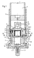
- Fig. 1 shows an overall designated 18 launcher in a throwing system for fog candles, explosive devices and. Like., With a launching cup 1, is connected to a launch tube 6 via a bayonet holder 11, wherein a projectile 7 is inserted into the launch tube 6.
- a direct current motor 2 is arranged coaxially to the longitudinal axis L of the launch device, the connecting lines 2.2 of which are led through the cup base 1.2 to the outside.
- the launcher can be arranged, for example, on a combat vehicle (not shown), the connecting lines 2.2 being connected to the on-board network (not shown) of the combat vehicle via a relay 15 (FIG. 3).
- a relay 15 FIG. 3
- an operating device arranged in the combat vehicle with an ignition device and a control computer for controlling the relay 15.
- a permanent magnet 5 is fixed so that it protrudes from the bottom 1.1 of the launch cup 1.
- the permanent magnet 5 projects into a recess 6.3 in the bottom part 6.1 of the launch tube 6.
- a protective hood 9 which is connected to the bottom 1.1 of the launch cup, in such a way that it can rotate freely within this protective hood.
- the permanent magnet 5 is surrounded by an ignition coil 10 with an iron core (not shown), which is arranged in the side walls of the recess 6.3.
- the ignition coil 10 is arranged within a potting compound so that it also protects against the weather is well protected. With the winding ends of the ignition coil 10, a squib 8 is connected, which is arranged in an upwardly open approach 6.2 of the bottom piece 6.1 and is therefore directly below the lower part of the throwing body 7.
- the rotating permanent magnet 5 When the electric motor 2 is started by the ignition device 17, the rotating permanent magnet 5 generates an alternating voltage in the ignition coil 10, which supplies the ignition current for the squib 8.
- the embodiment of the launcher 18 shown in FIG. 1 is further equipped with a device for inductive detection of the type of missile.
- coding pins 12 made of steel are arranged in a base arc 6.1 of the launch tube 6 on a circular arc around the longitudinal axis L such that their ends lie in the lower surface of the base portion 6.1.
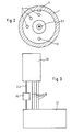
- electrical proximity switches 3 are arranged, so that their sensing ends in the bottom 1.1 of the launch cup 1 lie at predetermined angular intervals on a circular arc around the longitudinal axis L, the radius of which corresponds exactly to the circular arc on which the coding pins 12 are also arranged .
- the proximity switches 3 are located outside the electric motor 2 and the type of bayonet holder 11 between the launch tube 6 and launch cup 1 ensures that when the launch tube 6 is inserted in the launch cup 1, each coding pin 12 is opposite a proximity switch 3 (see FIG. 2). As shown in FIG. 3, the proximity switches 3 are connected via lines 16 to evaluation electronics arranged in the operating device 17. The three proximity switches 3 make it possible to obtain an identification signal relating to the type of throwing body, which is sent as a 3-bit binary value to the evaluation electronics is passed on, the different signal values being given by the fact that zero to a maximum of three coding pins 12 are arranged in the base piece 6.1 of the launch tube 6, which actuate the proximity switches 3 in the launch cup 1 when the launch tube 6 is mounted.
- the sensing pin 4 is arranged so that in the drawing, the upper end facing the inside of the launch tube 6 is at the top of the bottom piece 6.1 and a throwing body 7 inserted into the launch tube 6 sits with its lower edge on the sensing pin 4 and by its weight moves against the force of a compression spring 14 in the direction of the proximity switch 13 opposite it.
- the sensing pin 4 is relieved and raised by the force of the spring 14. This is recognized by the proximity switch 13 and a corresponding signal is sent to the evaluation electronics 17 via a line 16. The launch or a possible ignition failure can thus be recognized.
- the launch device 18 is operated from an operating device 17 which is arranged in the combat vehicle and, as mentioned, contains the ignition device and the control and evaluation device containing a control computer. If no shot is detected by sensor 13, the ammunition So sharp and the firing command is given by the control unit 17, the electric motor 2 is switched on via the ignition relay 15 for about 2 to 5 seconds. This is enough to ensure a safe ignition. The operator is informed by the control and evaluation electronics in the operating device 17 of the firing or a dud (misfire). There is also a main switch on the operating device 17, with which all the ignition relays for changing the ammunition can be blocked.
- FIG. 4 shows how a plurality of launching devices 18 'can be connected to a common operating device 17' via lines 2.2 'and 16' and ignition relays 15 '.
Landscapes
- Engineering & Computer Science (AREA)
- General Engineering & Computer Science (AREA)
- Electric Propulsion And Braking For Vehicles (AREA)
- Feeding, Discharge, Calcimining, Fusing, And Gas-Generation Devices (AREA)
- Control Of El Displays (AREA)
- Circuit Arrangements For Discharge Lamps (AREA)
- Air Bags (AREA)
Applications Claiming Priority (2)
| Application Number | Priority Date | Filing Date | Title |
|---|---|---|---|
| DE4004848A DE4004848A1 (de) | 1990-02-16 | 1990-02-16 | Vorrichtung zum induktiven zuenden der treibladung von wurfkoerpern und geschossen, insbesondere in einem wurfsystem fuer nebelkerzen, sprengkoerper u. dgl. |
| DE4004848 | 1990-02-16 |
Publications (3)
| Publication Number | Publication Date |
|---|---|
| EP0447757A2 true EP0447757A2 (fr) | 1991-09-25 |
| EP0447757A3 EP0447757A3 (en) | 1992-07-22 |
| EP0447757B1 EP0447757B1 (fr) | 1995-03-15 |
Family
ID=6400300
Family Applications (1)
| Application Number | Title | Priority Date | Filing Date |
|---|---|---|---|
| EP91100941A Expired - Lifetime EP0447757B1 (fr) | 1990-02-16 | 1991-01-25 | Dispositif pour l'allumage par induction de charges propulsives pour munition |
Country Status (3)
| Country | Link |
|---|---|
| EP (1) | EP0447757B1 (fr) |
| DE (2) | DE4004848A1 (fr) |
| NO (1) | NO173294C (fr) |
Cited By (1)
| Publication number | Priority date | Publication date | Assignee | Title |
|---|---|---|---|---|
| NL9301487A (nl) * | 1993-08-27 | 1995-03-16 | Halteren Metaal B V Van | Ondervraag- en identificatiesysteem ten gebruike bij geschut. |
Families Citing this family (5)
| Publication number | Priority date | Publication date | Assignee | Title |
|---|---|---|---|---|
| DE4137819A1 (de) * | 1991-11-16 | 1993-05-19 | Wegmann & Co Gmbh | Vorrichtung zum identifizieren von munition |
| DE19706605A1 (de) * | 1997-02-20 | 1998-08-27 | Dynamit Nobel Ag | Sekundärspule für ein induktives Anzündsystem |
| DE102010026639B4 (de) * | 2010-07-09 | 2019-12-12 | Diehl Defence Gmbh & Co. Kg | Trägervorrichtung für einen modularen Nebelwurfkörper |
| DE102012000114A1 (de) * | 2012-01-05 | 2013-07-11 | Rheinmetall Waffe Munition Gmbh | Vorrichtung zur Erkennung einer Geschossvorlage |
| DE202012008823U1 (de) | 2012-09-14 | 2012-11-23 | Rheinmetall Waffe Munition Gmbh | Vorrichtung zur Erkennung auch eines Zündversagers |
Family Cites Families (10)
| Publication number | Priority date | Publication date | Assignee | Title |
|---|---|---|---|---|
| US2459854A (en) * | 1946-04-18 | 1949-01-25 | Jr Willard E Swift | Grenade projector |
| DE2048743A1 (de) * | 1970-10-03 | 1973-05-30 | Mauser Werke Ag | Vorrichtung zum ausloesen einer initialzuendung fuer die treibladung von patronen auf elektrischem wege |
| AT330030B (de) * | 1973-02-15 | 1976-06-10 | Urbach Ing Erich | Werfer |
| DE2355255C2 (de) * | 1973-11-05 | 1984-05-10 | Gianni Verga Milano Casati | Anzündvorrichtung für Artillerietreibladungen |
| CH630756A5 (en) * | 1978-09-08 | 1982-06-30 | Mefina Sa | Device generating monophase current comprising a stator and a rotor |
| DE3343485C2 (de) * | 1983-12-01 | 1986-08-28 | Calor-Emag Elektrizitäts-Aktiengesellschaft, 4030 Ratingen | Impulstransformator für elektrische Zünder |
| DE3417614A1 (de) * | 1984-05-11 | 1985-11-14 | Dynamit Nobel Ag, 5210 Troisdorf | Waffenverschluss mit einem induktiven zuendenergie-uebertragungssystem |
| DE3705700A1 (de) * | 1987-02-23 | 1988-09-01 | Buck Chem Tech Werke | Werfereinheit |
| DE3822255A1 (de) * | 1988-07-01 | 1990-01-04 | Wegmann & Co | Wurfsystem fuer wurfkoerper, wie nebelkerzen und dergleichen |
| DE3844300C2 (de) * | 1988-12-30 | 1998-05-07 | Nico Pyrotechnik | Wurfsystem für Nebelkerzen, Sprengkörper und dergleichen |
-
1990
- 1990-02-16 DE DE4004848A patent/DE4004848A1/de not_active Withdrawn
-
1991
- 1991-01-25 EP EP91100941A patent/EP0447757B1/fr not_active Expired - Lifetime
- 1991-01-25 DE DE59104923T patent/DE59104923D1/de not_active Expired - Fee Related
- 1991-02-14 NO NO910594A patent/NO173294C/no not_active IP Right Cessation
Cited By (1)
| Publication number | Priority date | Publication date | Assignee | Title |
|---|---|---|---|---|
| NL9301487A (nl) * | 1993-08-27 | 1995-03-16 | Halteren Metaal B V Van | Ondervraag- en identificatiesysteem ten gebruike bij geschut. |
Also Published As
| Publication number | Publication date |
|---|---|
| NO173294B (no) | 1993-08-16 |
| EP0447757B1 (fr) | 1995-03-15 |
| EP0447757A3 (en) | 1992-07-22 |
| NO910594L (no) | 1991-08-19 |
| DE4004848A1 (de) | 1991-08-22 |
| DE59104923D1 (de) | 1995-04-20 |
| NO910594D0 (no) | 1991-02-14 |
| NO173294C (no) | 1993-11-24 |
Similar Documents
| Publication | Publication Date | Title |
|---|---|---|
| DE2706168C3 (de) | Vorrichtung zur Erzeugung eines elektrischen Zündstromes in einem Zünder für Geschosse | |
| DE1199662B (de) | Vorrichtung zum Ausloesen einer Sprengladung zur Bekaempfung von Bodenfahrzeugen | |
| DE2554152C3 (de) | Zündstromgenerator für einen elektrischen Geschoßzünder | |
| EP0447757B1 (fr) | Dispositif pour l'allumage par induction de charges propulsives pour munition | |
| DE2838381C2 (de) | Sicherheitsvorrichtung für Zündvorrichtungen | |
| DE834213C (de) | Vorrichtung zum Abfeuern von pyrotechnischen Koerpern | |
| DE4035325A1 (de) | Vorrichtung zur reichweitensteuerung von wurfkoerpern und geschossen, insbesondere in einem wurfsystem fuer nebelkerzen, sprengkoerper u. dgl. | |
| EP0156763B1 (fr) | Méthode et dispositif pour augmenter l'énergie dans une amorce électromagnétique | |
| DE2546220C3 (de) | Sicherungsvorrichtung für einen Stromerzeuger für einen Drallgeschoß-Zünder | |
| DE3325867A1 (de) | Elektromagnetische abschussvorrichtung fuer projektile | |
| DE2255547A1 (de) | Schalteinrichtung an elektrischen geschosszuendern | |
| DE2255479B2 (de) | Sicherungsvorrichtung an elektrischen Geschoßzündern | |
| DE2457946C2 (de) | Zündsystem für Geschosse | |
| DE1015349B (de) | Elektrischer Zuender fuer Geschosse | |
| DE1259740B (de) | Aufschlagzuender fuer Drallgeschosse | |
| DE2655886A1 (de) | Elektrischer zuender fuer geschosse | |
| DE3048752C2 (fr) | ||
| DE1140843B (de) | Elektrischer Geschosszuender mit Traegheitsgenerator | |
| DE3025280A1 (de) | Sicherungsvorrichtung fuer einen landminenzuender | |
| DE2946156C2 (fr) | ||
| DE3503013C1 (de) | Sicherheitseinrichtung | |
| DE1291260B (de) | Notabfeuerung fuer Geschuetze | |
| DE2203216C3 (de) | Elektrischer Zünder für Geschosse | |
| DE2366341C2 (de) | Vorrichtung zum Unterbrechen des elektrischen Sicherheitskurzschlußkreises | |
| AT42595B (de) | Elektrische Tempiervorrichtung für Zeitzündergeschosse mit Einheitspatrone. |
Legal Events
| Date | Code | Title | Description |
|---|---|---|---|
| PUAI | Public reference made under article 153(3) epc to a published international application that has entered the european phase |
Free format text: ORIGINAL CODE: 0009012 |
|
| AK | Designated contracting states |
Kind code of ref document: A2 Designated state(s): BE CH DE IT LI NL SE |
|
| PUAL | Search report despatched |
Free format text: ORIGINAL CODE: 0009013 |
|
| AK | Designated contracting states |
Kind code of ref document: A3 Designated state(s): BE CH DE IT LI NL SE |
|
| 17P | Request for examination filed |
Effective date: 19920806 |
|
| 17Q | First examination report despatched |
Effective date: 19940607 |
|
| GRAA | (expected) grant |
Free format text: ORIGINAL CODE: 0009210 |
|
| AK | Designated contracting states |
Kind code of ref document: B1 Designated state(s): BE CH DE IT LI NL SE |
|
| PG25 | Lapsed in a contracting state [announced via postgrant information from national office to epo] |
Ref country code: IT Free format text: LAPSE BECAUSE OF FAILURE TO SUBMIT A TRANSLATION OF THE DESCRIPTION OR TO PAY THE FEE WITHIN THE PRE;WARNING: LAPSES OF ITALIAN PATENTS WITH EFFECTIVE DATE BEFORE 2007 MAY HAVE OCCURRED AT ANY TIME BEFORE 2007. THE CORRECT EFFECTIVE DATE MAY BE DIFFERENT FROM THE ONE RECORDED.SCRIBED TIME-LIMIT Effective date: 19950315 Ref country code: BE Effective date: 19950315 |
|
| REF | Corresponds to: |
Ref document number: 59104923 Country of ref document: DE Date of ref document: 19950420 |
|
| PLBE | No opposition filed within time limit |
Free format text: ORIGINAL CODE: 0009261 |
|
| STAA | Information on the status of an ep patent application or granted ep patent |
Free format text: STATUS: NO OPPOSITION FILED WITHIN TIME LIMIT |
|
| 26N | No opposition filed | ||
| REG | Reference to a national code |
Ref country code: CH Ref legal event code: PFA Owner name: WEGMANN & CO. GMBH Free format text: WEGMANN & CO. GMBH#AUGUST-BODE-STRASSE 1#D-34127 KASSEL (DE) -TRANSFER TO- WEGMANN & CO. GMBH#AUGUST-BODE-STRASSE 1#D-34127 KASSEL (DE) |
|
| PGFP | Annual fee paid to national office [announced via postgrant information from national office to epo] |
Ref country code: DE Payment date: 20090204 Year of fee payment: 19 Ref country code: NL Payment date: 20090122 Year of fee payment: 19 |
|
| PGFP | Annual fee paid to national office [announced via postgrant information from national office to epo] |
Ref country code: CH Payment date: 20090126 Year of fee payment: 19 |
|
| PGFP | Annual fee paid to national office [announced via postgrant information from national office to epo] |
Ref country code: SE Payment date: 20090126 Year of fee payment: 19 |
|
| REG | Reference to a national code |
Ref country code: NL Ref legal event code: V1 Effective date: 20100801 |
|
| REG | Reference to a national code |
Ref country code: CH Ref legal event code: PL |
|
| EUG | Se: european patent has lapsed | ||
| PG25 | Lapsed in a contracting state [announced via postgrant information from national office to epo] |
Ref country code: LI Free format text: LAPSE BECAUSE OF NON-PAYMENT OF DUE FEES Effective date: 20100131 Ref country code: CH Free format text: LAPSE BECAUSE OF NON-PAYMENT OF DUE FEES Effective date: 20100131 Ref country code: NL Free format text: LAPSE BECAUSE OF NON-PAYMENT OF DUE FEES Effective date: 20100801 |
|
| PG25 | Lapsed in a contracting state [announced via postgrant information from national office to epo] |
Ref country code: DE Free format text: LAPSE BECAUSE OF NON-PAYMENT OF DUE FEES Effective date: 20100803 |
|
| PG25 | Lapsed in a contracting state [announced via postgrant information from national office to epo] |
Ref country code: SE Free format text: LAPSE BECAUSE OF NON-PAYMENT OF DUE FEES Effective date: 20100126 |