EP0447619B1 - Warneinrichtung mit einer Messzelle und Alarmgebern zur Anzeige des Erschöpfungszustandes eines Gasfilters - Google Patents
Warneinrichtung mit einer Messzelle und Alarmgebern zur Anzeige des Erschöpfungszustandes eines Gasfilters Download PDFInfo
- Publication number
- EP0447619B1 EP0447619B1 EP90121361A EP90121361A EP0447619B1 EP 0447619 B1 EP0447619 B1 EP 0447619B1 EP 90121361 A EP90121361 A EP 90121361A EP 90121361 A EP90121361 A EP 90121361A EP 0447619 B1 EP0447619 B1 EP 0447619B1
- Authority
- EP
- European Patent Office
- Prior art keywords
- gas filter
- flap piece
- warning arrangement
- warning
- arrangement according
- Prior art date
- Legal status (The legal status is an assumption and is not a legal conclusion. Google has not performed a legal analysis and makes no representation as to the accuracy of the status listed.)
- Expired - Lifetime
Links
- 230000029058 respiratory gaseous exchange Effects 0.000 claims abstract description 29
- 238000005259 measurement Methods 0.000 claims description 10
- 230000001960 triggered effect Effects 0.000 claims description 3
- 239000004065 semiconductor Substances 0.000 claims description 2
- 238000002848 electrochemical method Methods 0.000 claims 1
- 239000007789 gas Substances 0.000 description 18
- 238000010586 diagram Methods 0.000 description 4
- 239000003344 environmental pollutant Substances 0.000 description 4
- 231100000719 pollutant Toxicity 0.000 description 4
- 230000003287 optical effect Effects 0.000 description 3
- 238000001514 detection method Methods 0.000 description 2
- LELOWRISYMNNSU-UHFFFAOYSA-N hydrogen cyanide Chemical compound N#C LELOWRISYMNNSU-UHFFFAOYSA-N 0.000 description 2
- 230000000717 retained effect Effects 0.000 description 2
- UGFAIRIUMAVXCW-UHFFFAOYSA-N Carbon monoxide Chemical compound [O+]#[C-] UGFAIRIUMAVXCW-UHFFFAOYSA-N 0.000 description 1
- ZAMOUSCENKQFHK-UHFFFAOYSA-N Chlorine atom Chemical compound [Cl] ZAMOUSCENKQFHK-UHFFFAOYSA-N 0.000 description 1
- RWSOTUBLDIXVET-UHFFFAOYSA-N Dihydrogen sulfide Chemical compound S RWSOTUBLDIXVET-UHFFFAOYSA-N 0.000 description 1
- QVGXLLKOCUKJST-UHFFFAOYSA-N atomic oxygen Chemical compound [O] QVGXLLKOCUKJST-UHFFFAOYSA-N 0.000 description 1
- 230000000903 blocking effect Effects 0.000 description 1
- 229910002091 carbon monoxide Inorganic materials 0.000 description 1
- 239000000460 chlorine Substances 0.000 description 1
- 229910052801 chlorine Inorganic materials 0.000 description 1
- 230000001419 dependent effect Effects 0.000 description 1
- 238000011161 development Methods 0.000 description 1
- 230000018109 developmental process Effects 0.000 description 1
- 238000006056 electrooxidation reaction Methods 0.000 description 1
- 229910000037 hydrogen sulfide Inorganic materials 0.000 description 1
- 239000001301 oxygen Substances 0.000 description 1
- 229910052760 oxygen Inorganic materials 0.000 description 1
- 238000011144 upstream manufacturing Methods 0.000 description 1
Images
Classifications
-
- A—HUMAN NECESSITIES
- A62—LIFE-SAVING; FIRE-FIGHTING
- A62B—DEVICES, APPARATUS OR METHODS FOR LIFE-SAVING
- A62B18/00—Breathing masks or helmets, e.g. affording protection against chemical agents or for use at high altitudes or incorporating a pump or compressor for reducing the inhalation effort
- A62B18/08—Component parts for gas-masks or gas-helmets, e.g. windows, straps, speech transmitters, signal-devices
- A62B18/088—Devices for indicating filter saturation
Definitions
- the invention relates to a warning device with a measuring cell and alarm transmitters for displaying the state of exhaustion of a gas filter in connection with a breathing connection, the warning device being designed as a unit separate from the gas filter.
- Such a warning device is already known from DE-A-36 13 512.
- Optical and acoustic signal indicators are used in an electronic circuit arrangement as alarm devices, the measured value triggering the alarm being determined by means of an electrochemical measuring cell.
- the use of optical and acoustic signals as alarm devices can be ignored or overlooked by the device wearer in the event of noise or poor visibility.
- the object of the invention is therefore to create a warning device of the type mentioned at the outset which clearly and safely indicates to the device wearer the state of exhaustion of the gas filter even in the event of noise and poor visibility.
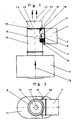
- the warning device 1 essentially consists of a housing 2 into which a measuring cell 3, an electronic circuit 4 connected to it in terms of circuitry, a battery 5, a pivotable mechanical device 6 with a permanent magnet 7 and an electromagnetic interrupter 7 a is arranged.
- the warning device 1 is flanged to an upright breathing tube 8 via a lateral opening 9 and is in flow connection with the breathing tube.
- the breathing tube 8 is designed as a functional part for the warning device 1 and has a stop element 10 against which the pivotable flap piece 14 bears in an end position.
- the breathing tube 8 with the warning device 1 is connected behind the latter in the flow direction 12 to indicate the state of exhaustion of a gas filter 11.
- the direction of flow 12 is synonymous with the direction of the inhaled air.
- the breathing tube 8 is connected in the flow direction with its opening 13 to a breathing tube, not shown in the drawing, with a breath connection.
- the mechanical device 6, which is controlled via the measuring cell 3 and the electronic circuit 4, closes the flow cross section of the breathing tube 8 with its pivotable flap piece 14 when the gas filter 11 is exhausted and thus shows the wearer of the gas filter 11 by increasing the breathing resistance.
- the mechanical device 6 consists essentially of a circular flap piece 14, an axis of rotation 15 which is fixed on the edge of the flap piece and a spring drive 16 which, when triggered, swings the flap piece into the breathing tube 8 against the stop element 10.
- the flap piece 14 has a slightly smaller diameter than the inside diameter of the breathing tube 8. Concentric to the circular flap piece 14, an opening 17 is machined into it, through which the device wearer can breathe when the flap piece 14 closes the flow cross section of the breathing tube 8 in the event of an indication of exhaustion. The remaining cross-section of the opening 17 then causes the device wearer to increase the inhalation resistance. At one end of the axis of rotation 15, a lever 18 is arranged, on which the device carrier can manually pivot the flap piece 14 blocking the flow cross section of the breathing tube 8 into the starting position, ie to rest against the permanent magnet 7, so that the full flow cross section of the breathing tube 8 can be inhaled is available again. The increased inhalation resistance is then lower again for the device wearer.
- the manual pivoting back of the flap piece 14 by means of the lever 18 corresponds to the acknowledgment of the triggered display of the state of exhaustion of the gas filter 11 which retains the harmful gases.
- the device carrier thus warned can then leave the pollutant-containing room for the time to replace the gas filter, with sufficient time.
- an electromotive drive (not shown in the drawing) for pivoting into the flow cross section of the breathing tube 8 can be provided on the flap piece 14, an acknowledgment switch (also not shown in the drawing) causing the flap piece 14 to pivot back electromotively.
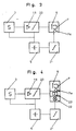
- Fig. 3 the electronic circuit arrangement of the warning device 1 is shown as a block diagram.
- the measuring cell 3 is a signal amplifier 19 and this a threshold switch 20 and as an alarm, the mechanical device 6 according to the invention with the permanent magnet 7 and the electromagnetic interrupter 7 a downstream.
- the battery 5 is provided with a battery monitor 21 for supplying power to the circuit arrangement.
- the switching threshold of the threshold switch 20 is set to the measurement signal corresponding to the measurement value which triggers the alarm corresponds to a certain harmful gas concentration, which indicates the end of the period of use of the gas filter 11.
- the measuring signal coming from the measuring cell 3 exceeds the set switching threshold (alarm threshold) of the threshold switch 20, its output is turned on and the electromagnetic interrupter 7 a is activated such that the magnet 7 is deactivated and the held flap piece 14 is released, which is then released by means of the
- the spring drive 16 swings suddenly into the breathing tube 8 and comes to rest against the stop 10 in the end position.
- the flap piece 14 closes the flow cross section of the breathing tube 8 and only the opening 17, which is worked in concentrically in the flap piece, remains as a passage for inhalation for the device wearer. Due to the relatively small opening 17, the inhalation resistance increases noticeably. This is then the sign for the equipment carrier that the gas filter 11 will be exhausted in a short time.
- FIG. 4 shows a block diagram of the warning device 1, in which, in addition to the flap device 6 described above and connected in parallel to it, a light-emitting diode 22 is provided as an optical alarm transmitter and a signal transmitter 23 as an acoustic alarm transmitter.
- An electrochemical measuring cell can be provided as the measuring cell 3, which works on the principle of electrochemical oxidation. It serves as a measuring element for the detection of harmful concentrations of harmful gas in the inhaled air, which can no longer be retained or removed by the gas filter 11 connected upstream of the measuring element in the event of being exhausted. In other words: the measuring element 3 measures a certain harmful pollutant concentration, which indicates that the pollutant retained in the gas filter 11 breaks through, which means that the gas filter is exhausted. Electrochemical measuring cells already exist for the detection of carbon monoxide, chlorine, hydrogen sulfide, hydrocyanic acid and oxygen, which can be used in the warning device 1 for the corresponding gas filter.
- a semiconductor sensor can be used as the measuring element, as a result of which a larger number of pollutants to be detected can advantageously be measured.
Landscapes
- Health & Medical Sciences (AREA)
- Pulmonology (AREA)
- General Health & Medical Sciences (AREA)
- Business, Economics & Management (AREA)
- Emergency Management (AREA)
- Respiratory Apparatuses And Protective Means (AREA)
- Fuel Cell (AREA)
- Sampling And Sample Adjustment (AREA)
- Investigating Or Analyzing Materials By The Use Of Fluid Adsorption Or Reactions (AREA)
- Burglar Alarm Systems (AREA)
Priority Applications (1)
| Application Number | Priority Date | Filing Date | Title |
|---|---|---|---|
| AT90121361T ATE97824T1 (de) | 1990-03-21 | 1990-11-08 | Warneinrichtung mit einer messzelle und alarmgebern zur anzeige des erschoepfungszustandes eines gasfilters. |
Applications Claiming Priority (2)
| Application Number | Priority Date | Filing Date | Title |
|---|---|---|---|
| DE4009107 | 1990-03-21 | ||
| DE4009107A DE4009107A1 (de) | 1990-03-21 | 1990-03-21 | Warneinrichtung mit einer messzelle und alarmgebern zur anzeige des erschoefpungszustandes eines gasfilters |
Publications (2)
| Publication Number | Publication Date |
|---|---|
| EP0447619A1 EP0447619A1 (de) | 1991-09-25 |
| EP0447619B1 true EP0447619B1 (de) | 1993-12-01 |
Family
ID=6402758
Family Applications (1)
| Application Number | Title | Priority Date | Filing Date |
|---|---|---|---|
| EP90121361A Expired - Lifetime EP0447619B1 (de) | 1990-03-21 | 1990-11-08 | Warneinrichtung mit einer Messzelle und Alarmgebern zur Anzeige des Erschöpfungszustandes eines Gasfilters |
Country Status (4)
| Country | Link |
|---|---|
| EP (1) | EP0447619B1 (enExample) |
| AT (1) | ATE97824T1 (enExample) |
| DE (2) | DE4009107A1 (enExample) |
| NO (1) | NO905329L (enExample) |
Families Citing this family (9)
| Publication number | Priority date | Publication date | Assignee | Title |
|---|---|---|---|---|
| AU645959B3 (en) * | 1993-11-05 | 1994-01-27 | Purecab (Australia) Pty Ltd | Respiratory filter indicator |
| US5666949A (en) * | 1994-10-24 | 1997-09-16 | Minnesota Mining And Manufacturing Company | Exposure indicator with continuous alarm signal indicating multiple conditions |
| US5659296A (en) * | 1994-10-24 | 1997-08-19 | Minnesota Mining And Manufacturing Company | Exposure indicating apparatus |
| DE29504087U1 (de) * | 1995-03-10 | 1995-08-10 | Palocz-Andresen, Michael, Dr.-Ing.habil., 20459 Hamburg | Mikro-Meßvorrichtung für die Erfassung der Beladung von Filtern |
| AUPN191095A0 (en) * | 1995-03-23 | 1995-04-27 | Safety Equipment Australia Pty Ltd | Positive air-purifying respirator management system |
| DE19650897A1 (de) * | 1996-12-07 | 1998-06-10 | T E M Tech Entwicklung Und Man | Apparat und Verfahren zur Erhöhung der Sicherheit von Atemschutzmasken |
| US6186140B1 (en) * | 1997-03-14 | 2001-02-13 | 3M Innovative Properties Company | Respiratory filter element having a storage device for keeping track of filter usage and a system for use therewith |
| DE19911867C2 (de) * | 1999-03-17 | 2002-02-21 | T E M Techn Entwicklungen Und | Sensorsystem zur Detektion von Gasen und Dämpfen in Luft |
| KR20020001781A (ko) | 1999-03-17 | 2002-01-09 | 추후제출 | 공기내에 포함되어 있는 가스 또는 연기를 검출하기 위한방법 및 센서 장치 |
Family Cites Families (5)
| Publication number | Priority date | Publication date | Assignee | Title |
|---|---|---|---|---|
| US1676125A (en) * | 1928-07-03 | Device for indicating admixtures to gases and liquids | ||
| DE670550C (de) * | 1929-04-10 | 1939-01-20 | Bernh Draeger | Sauerstoffatemschutzgeraet |
| DE693685C (de) * | 1935-11-19 | 1940-07-17 | Auergesellschaft Akt Ges | Warnvorrichtung fuer Sauerstoffatemschutzgeraete |
| FR1353343A (fr) * | 1963-04-09 | 1964-02-21 | Avertisseur pour appareils protecteurs des voies respiratoires | |
| DE3613512C3 (de) * | 1986-04-22 | 1994-09-29 | Auergesellschaft Gmbh | Elektrische Warneinrichtung zur Anzeige des Erschöpfungszustandes eines Schadgase zurückhaltenden Gasfilters |
-
1990
- 1990-03-21 DE DE4009107A patent/DE4009107A1/de active Granted
- 1990-11-08 AT AT90121361T patent/ATE97824T1/de not_active IP Right Cessation
- 1990-11-08 EP EP90121361A patent/EP0447619B1/de not_active Expired - Lifetime
- 1990-11-08 DE DE90121361T patent/DE59003710D1/de not_active Expired - Fee Related
- 1990-12-10 NO NO90905329A patent/NO905329L/no unknown
Also Published As
| Publication number | Publication date |
|---|---|
| NO905329D0 (no) | 1990-12-10 |
| DE4009107C2 (enExample) | 1993-06-09 |
| DE59003710D1 (de) | 1994-01-13 |
| NO905329L (no) | 1991-09-23 |
| EP0447619A1 (de) | 1991-09-25 |
| ATE97824T1 (de) | 1993-12-15 |
| DE4009107A1 (de) | 1991-09-26 |
Similar Documents
| Publication | Publication Date | Title |
|---|---|---|
| DE3613512C2 (enExample) | ||
| DE69634169T2 (de) | Strombetriebenes luftreinigungs-beatmungs-management-system | |
| DE69313984T2 (de) | Vorrichtung zur anzeige der anwesenheit von kohlendioxid in der ausatemluft eines patienten | |
| DE2944444C2 (enExample) | ||
| DE68909693T2 (de) | Angetriebenes Atemgerät. | |
| EP0447619B1 (de) | Warneinrichtung mit einer Messzelle und Alarmgebern zur Anzeige des Erschöpfungszustandes eines Gasfilters | |
| DE69015622T2 (de) | Verfahren zum nachweis von in der luft suspendierten allergenen. | |
| DE69533138T2 (de) | Expositionsmelder | |
| DE60021016T2 (de) | Zellulares Telephongerät ausgerüstet mit einer Gaskomponentenmessfunktion | |
| DE60223527T2 (de) | Verfahren und messgerät zur messung der stickoxidkonzentration in der ausatemluft | |
| DE3515432C2 (enExample) | ||
| DE2852491A1 (de) | Vorrichtung zum messen des atmungswiderstands eines patienten | |
| DE69718958T2 (de) | Überwachungsanordnung | |
| EP1165186B1 (de) | Verfahren und sensorvorrichtung zur detektion von in luft enthaltenen gasen oder dämpfen | |
| DE102006051571B3 (de) | Verfahren zur Bestimmung des Verbrauchs eines CO2-Absorbers in einer Beatmungsvorrichtung mit Rückatemsystem | |
| DE2428352A1 (de) | Anordnung zur bestimmung der alkoholkonzentration der (tiefen) lungenluft | |
| EP1232393B1 (de) | Atemalkoholmessgerät | |
| WO2021108822A1 (de) | Lungentestvorrichtung | |
| DE19911869B4 (de) | Neuartige Atemschutzmaske mit Sensor-Mikrosystem und Verfahren zum Betreiben derselben | |
| CN2906427Y (zh) | 室内二氧化碳及污染气体监控装置 | |
| EP2539225B1 (de) | Kreislauftauchgerät mit einem mundstück | |
| DE2909578A1 (de) | System zur erfassung der zeigerstellung eines messgeraetes | |
| DE102023106966A1 (de) | Vorrichtung und verfahren zur durchführung eines hypoxie-trainings | |
| CN212845258U (zh) | 一种车载甲醛检测装置 | |
| DE1163153B (de) | Warnvorrichtung fuer Druckgasatemschutzgeraete |
Legal Events
| Date | Code | Title | Description |
|---|---|---|---|
| PUAI | Public reference made under article 153(3) epc to a published international application that has entered the european phase |
Free format text: ORIGINAL CODE: 0009012 |
|
| 17P | Request for examination filed |
Effective date: 19901122 |
|
| AK | Designated contracting states |
Kind code of ref document: A1 Designated state(s): AT BE CH DE ES FR GB GR IT LI LU NL |
|
| 17Q | First examination report despatched |
Effective date: 19930318 |
|
| GRAA | (expected) grant |
Free format text: ORIGINAL CODE: 0009210 |
|
| AK | Designated contracting states |
Kind code of ref document: B1 Designated state(s): AT BE CH DE ES FR GB GR IT LI LU NL |
|
| PG25 | Lapsed in a contracting state [announced via postgrant information from national office to epo] |
Ref country code: GR Free format text: LAPSE BECAUSE OF FAILURE TO SUBMIT A TRANSLATION OF THE DESCRIPTION OR TO PAY THE FEE WITHIN THE PRESCRIBED TIME-LIMIT Effective date: 19931201 |
|
| REF | Corresponds to: |
Ref document number: 97824 Country of ref document: AT Date of ref document: 19931215 Kind code of ref document: T |
|
| REF | Corresponds to: |
Ref document number: 59003710 Country of ref document: DE Date of ref document: 19940113 |
|
| GBT | Gb: translation of ep patent filed (gb section 77(6)(a)/1977) |
Effective date: 19940114 |
|
| ITF | It: translation for a ep patent filed | ||
| REG | Reference to a national code |
Ref country code: ES Ref legal event code: BA2A |
|
| ET | Fr: translation filed | ||
| REG | Reference to a national code |
Ref country code: GR Ref legal event code: FG4A Free format text: 3010719 |
|
| PLBE | No opposition filed within time limit |
Free format text: ORIGINAL CODE: 0009261 |
|
| STAA | Information on the status of an ep patent application or granted ep patent |
Free format text: STATUS: NO OPPOSITION FILED WITHIN TIME LIMIT |
|
| PG25 | Lapsed in a contracting state [announced via postgrant information from national office to epo] |
Ref country code: AT Effective date: 19941108 |
|
| PG25 | Lapsed in a contracting state [announced via postgrant information from national office to epo] |
Ref country code: ES Free format text: LAPSE BECAUSE OF NON-PAYMENT OF DUE FEES Effective date: 19941109 |
|
| 26N | No opposition filed | ||
| PG25 | Lapsed in a contracting state [announced via postgrant information from national office to epo] |
Ref country code: LU Free format text: LAPSE BECAUSE OF NON-PAYMENT OF DUE FEES Effective date: 19941130 Ref country code: LI Effective date: 19941130 Ref country code: CH Effective date: 19941130 |
|
| REG | Reference to a national code |
Ref country code: CH Ref legal event code: PL Ref country code: GR Ref legal event code: MM2A Free format text: 3010719 |
|
| PG25 | Lapsed in a contracting state [announced via postgrant information from national office to epo] |
Ref country code: DE Effective date: 19950801 |
|
| PGFP | Annual fee paid to national office [announced via postgrant information from national office to epo] |
Ref country code: GB Payment date: 19951103 Year of fee payment: 6 |
|
| PGFP | Annual fee paid to national office [announced via postgrant information from national office to epo] |
Ref country code: BE Payment date: 19951116 Year of fee payment: 6 |
|
| PGFP | Annual fee paid to national office [announced via postgrant information from national office to epo] |
Ref country code: FR Payment date: 19951120 Year of fee payment: 6 |
|
| PGFP | Annual fee paid to national office [announced via postgrant information from national office to epo] |
Ref country code: NL Payment date: 19951130 Year of fee payment: 6 |
|
| PG25 | Lapsed in a contracting state [announced via postgrant information from national office to epo] |
Ref country code: GB Effective date: 19961108 |
|
| PG25 | Lapsed in a contracting state [announced via postgrant information from national office to epo] |
Ref country code: BE Effective date: 19961130 |
|
| REG | Reference to a national code |
Ref country code: ES Ref legal event code: FA2A Effective date: 19970325 |
|
| BERE | Be: lapsed |
Owner name: AUERGESELLSCHAFT G.M.B.H. Effective date: 19961130 |
|
| PG25 | Lapsed in a contracting state [announced via postgrant information from national office to epo] |
Ref country code: NL Effective date: 19970601 |
|
| GBPC | Gb: european patent ceased through non-payment of renewal fee |
Effective date: 19961108 |
|
| PG25 | Lapsed in a contracting state [announced via postgrant information from national office to epo] |
Ref country code: FR Effective date: 19970731 |
|
| NLV4 | Nl: lapsed or anulled due to non-payment of the annual fee |
Effective date: 19970601 |
|
| REG | Reference to a national code |
Ref country code: FR Ref legal event code: ST |
|
| PG25 | Lapsed in a contracting state [announced via postgrant information from national office to epo] |
Ref country code: IT Free format text: LAPSE BECAUSE OF NON-PAYMENT OF DUE FEES;WARNING: LAPSES OF ITALIAN PATENTS WITH EFFECTIVE DATE BEFORE 2007 MAY HAVE OCCURRED AT ANY TIME BEFORE 2007. THE CORRECT EFFECTIVE DATE MAY BE DIFFERENT FROM THE ONE RECORDED. Effective date: 20051108 |