EP0447619B1 - Warning system with a measuring cell and alarm signal to indicate the condition of a gas filter - Google Patents
Warning system with a measuring cell and alarm signal to indicate the condition of a gas filter Download PDFInfo
- Publication number
- EP0447619B1 EP0447619B1 EP90121361A EP90121361A EP0447619B1 EP 0447619 B1 EP0447619 B1 EP 0447619B1 EP 90121361 A EP90121361 A EP 90121361A EP 90121361 A EP90121361 A EP 90121361A EP 0447619 B1 EP0447619 B1 EP 0447619B1
- Authority
- EP
- European Patent Office
- Prior art keywords
- gas filter
- flap piece
- warning arrangement
- warning
- arrangement according
- Prior art date
- Legal status (The legal status is an assumption and is not a legal conclusion. Google has not performed a legal analysis and makes no representation as to the accuracy of the status listed.)
- Expired - Lifetime
Links
Images
Classifications
-
- A—HUMAN NECESSITIES
- A62—LIFE-SAVING; FIRE-FIGHTING
- A62B—DEVICES, APPARATUS OR METHODS FOR LIFE-SAVING
- A62B18/00—Breathing masks or helmets, e.g. affording protection against chemical agents or for use at high altitudes or incorporating a pump or compressor for reducing the inhalation effort
- A62B18/08—Component parts for gas-masks or gas-helmets, e.g. windows, straps, speech transmitters, signal-devices
- A62B18/088—Devices for indicating filter saturation
Definitions
- the invention relates to a warning device with a measuring cell and alarm transmitters for displaying the state of exhaustion of a gas filter in connection with a breathing connection, the warning device being designed as a unit separate from the gas filter.
- Such a warning device is already known from DE-A-36 13 512.
- Optical and acoustic signal indicators are used in an electronic circuit arrangement as alarm devices, the measured value triggering the alarm being determined by means of an electrochemical measuring cell.
- the use of optical and acoustic signals as alarm devices can be ignored or overlooked by the device wearer in the event of noise or poor visibility.
- the object of the invention is therefore to create a warning device of the type mentioned at the outset which clearly and safely indicates to the device wearer the state of exhaustion of the gas filter even in the event of noise and poor visibility.
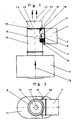
- the warning device 1 essentially consists of a housing 2 into which a measuring cell 3, an electronic circuit 4 connected to it in terms of circuitry, a battery 5, a pivotable mechanical device 6 with a permanent magnet 7 and an electromagnetic interrupter 7 a is arranged.
- the warning device 1 is flanged to an upright breathing tube 8 via a lateral opening 9 and is in flow connection with the breathing tube.
- the breathing tube 8 is designed as a functional part for the warning device 1 and has a stop element 10 against which the pivotable flap piece 14 bears in an end position.
- the breathing tube 8 with the warning device 1 is connected behind the latter in the flow direction 12 to indicate the state of exhaustion of a gas filter 11.
- the direction of flow 12 is synonymous with the direction of the inhaled air.
- the breathing tube 8 is connected in the flow direction with its opening 13 to a breathing tube, not shown in the drawing, with a breath connection.
- the mechanical device 6, which is controlled via the measuring cell 3 and the electronic circuit 4, closes the flow cross section of the breathing tube 8 with its pivotable flap piece 14 when the gas filter 11 is exhausted and thus shows the wearer of the gas filter 11 by increasing the breathing resistance.
- the mechanical device 6 consists essentially of a circular flap piece 14, an axis of rotation 15 which is fixed on the edge of the flap piece and a spring drive 16 which, when triggered, swings the flap piece into the breathing tube 8 against the stop element 10.
- the flap piece 14 has a slightly smaller diameter than the inside diameter of the breathing tube 8. Concentric to the circular flap piece 14, an opening 17 is machined into it, through which the device wearer can breathe when the flap piece 14 closes the flow cross section of the breathing tube 8 in the event of an indication of exhaustion. The remaining cross-section of the opening 17 then causes the device wearer to increase the inhalation resistance. At one end of the axis of rotation 15, a lever 18 is arranged, on which the device carrier can manually pivot the flap piece 14 blocking the flow cross section of the breathing tube 8 into the starting position, ie to rest against the permanent magnet 7, so that the full flow cross section of the breathing tube 8 can be inhaled is available again. The increased inhalation resistance is then lower again for the device wearer.
- the manual pivoting back of the flap piece 14 by means of the lever 18 corresponds to the acknowledgment of the triggered display of the state of exhaustion of the gas filter 11 which retains the harmful gases.
- the device carrier thus warned can then leave the pollutant-containing room for the time to replace the gas filter, with sufficient time.
- an electromotive drive (not shown in the drawing) for pivoting into the flow cross section of the breathing tube 8 can be provided on the flap piece 14, an acknowledgment switch (also not shown in the drawing) causing the flap piece 14 to pivot back electromotively.
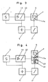
- Fig. 3 the electronic circuit arrangement of the warning device 1 is shown as a block diagram.
- the measuring cell 3 is a signal amplifier 19 and this a threshold switch 20 and as an alarm, the mechanical device 6 according to the invention with the permanent magnet 7 and the electromagnetic interrupter 7 a downstream.
- the battery 5 is provided with a battery monitor 21 for supplying power to the circuit arrangement.
- the switching threshold of the threshold switch 20 is set to the measurement signal corresponding to the measurement value which triggers the alarm corresponds to a certain harmful gas concentration, which indicates the end of the period of use of the gas filter 11.
- the measuring signal coming from the measuring cell 3 exceeds the set switching threshold (alarm threshold) of the threshold switch 20, its output is turned on and the electromagnetic interrupter 7 a is activated such that the magnet 7 is deactivated and the held flap piece 14 is released, which is then released by means of the
- the spring drive 16 swings suddenly into the breathing tube 8 and comes to rest against the stop 10 in the end position.
- the flap piece 14 closes the flow cross section of the breathing tube 8 and only the opening 17, which is worked in concentrically in the flap piece, remains as a passage for inhalation for the device wearer. Due to the relatively small opening 17, the inhalation resistance increases noticeably. This is then the sign for the equipment carrier that the gas filter 11 will be exhausted in a short time.
- FIG. 4 shows a block diagram of the warning device 1, in which, in addition to the flap device 6 described above and connected in parallel to it, a light-emitting diode 22 is provided as an optical alarm transmitter and a signal transmitter 23 as an acoustic alarm transmitter.
- An electrochemical measuring cell can be provided as the measuring cell 3, which works on the principle of electrochemical oxidation. It serves as a measuring element for the detection of harmful concentrations of harmful gas in the inhaled air, which can no longer be retained or removed by the gas filter 11 connected upstream of the measuring element in the event of being exhausted. In other words: the measuring element 3 measures a certain harmful pollutant concentration, which indicates that the pollutant retained in the gas filter 11 breaks through, which means that the gas filter is exhausted. Electrochemical measuring cells already exist for the detection of carbon monoxide, chlorine, hydrogen sulfide, hydrocyanic acid and oxygen, which can be used in the warning device 1 for the corresponding gas filter.
- a semiconductor sensor can be used as the measuring element, as a result of which a larger number of pollutants to be detected can advantageously be measured.
Abstract
Description
Die Erfindung bezieht sich auf eine Warneinrichtung mit einer Meßzelle und Alarmgebern zur Anzeige des Erschöpfungszustandes eines Gasfilters in Verbindung mit einem Atemanschluß, wobei die Warneinrichtung als eine vom Gasfilter getrennte Einheit ausgebildet ist.The invention relates to a warning device with a measuring cell and alarm transmitters for displaying the state of exhaustion of a gas filter in connection with a breathing connection, the warning device being designed as a unit separate from the gas filter.
Eine derartige Warneinrichtung ist bereits aus der DE-A-36 13 512 bekannt. Hierbei werden als Alarmgeber optische und akustische Signalanzeiger in einer elektronischen Schaltungsanordnung verwendet, wobei der den alarmauslösende Meßwert mittels einer elektrochemischen Meßzelle ermittelt wird. Die Verwendung von optischen und akustischen Signalen als Alarmgeber, kann vom Gerätträger bei Lärm oder bei schlechten Sichtverhältnissen überhört oder übersehen werden.Such a warning device is already known from DE-A-36 13 512. Optical and acoustic signal indicators are used in an electronic circuit arrangement as alarm devices, the measured value triggering the alarm being determined by means of an electrochemical measuring cell. The use of optical and acoustic signals as alarm devices can be ignored or overlooked by the device wearer in the event of noise or poor visibility.
Der Erfindung liegt deshalb die Aufgabe zugrunde, eine Warneinrichtung der eingangs genannten Art zu schaffen, die eindeutig und sicher dem Gerätträger auch bei Lärm und schlechter Sicht den Erschöpfungszustand des Gasfilters anzeigt.The object of the invention is therefore to create a warning device of the type mentioned at the outset which clearly and safely indicates to the device wearer the state of exhaustion of the gas filter even in the event of noise and poor visibility.
Diese Aufgabe wird durch die kennzeichnenden Merkmale des Patentanspruchs 1 gelöst.This object is achieved by the characterizing features of
Vorteilhafte Weiterentwicklungen sind in den abhängigen Ansprüchen gekennzeichnet.Advantageous further developments are characterized in the dependent claims.
Ein Ausführungsbeispiel des Erfindungsgegenstandes ist in der Zeichnung dargestellt. Es zeigen:
- Fig. 1
- eine Seitenansicht der Warneinrichtung, die in Strömungsrichtung hinter einem Gasfilter angeordnet ist,
- Fig. 2
- eine Draufsicht nach Fig. 1,
- Fig. 3
- eine Ausführung der Warneinrichtung als Blockschaltbild und
- Fig. 4
- eine andere Ausführung der Warneinrichtung als Blockschaltbild
- Fig. 1
- 2 shows a side view of the warning device which is arranged behind a gas filter in the direction of flow,
- Fig. 2
- 2 shows a top view according to FIG. 1,
- Fig. 3
- an execution of the warning device as a block diagram and
- Fig. 4
- another version of the warning device as a block diagram
Wie aus den Figuren 1 und 3 ersichtlich ist, besteht die Warneinrichtung 1 im wesentlichen aus einem Gehäuse 2, in das eine Meßzelle 3, eine mit dieser schaltungstechnisch verbundene elektronische Schaltung 4, eine Batterie 5, eine schwenkbare mechanische Vorrichtung 6 mit einem Permanentmagnet 7 und ein elektromagnetischer Unterbrecher 7 a angeordnet ist. Die Warneinrichtung 1 ist an einem hochstehenden Atemrohr 8 über eine seitliche Öffnung 9 angeflanscht und steht mit dem Atemrohr in strömungsmäßiger Verbindung. Das Atemrohr 8 ist als ein Funktionsteil für die Warneinrichtung 1 ausgebildet und weist ein Anschlagelement 10 auf, gegen das in einer Endstellung das schwenkbare Klappenstück 14 anliegt. Das Atemrohr 8 mit der Warneinrichtung 1 ist zur Anzeige des Erschöpfungszustandes eines Gasfilters 11, hinter diesen in Strömungsrichtung 12 geschaltet. Die Strömungsrichtung 12 ist gleichbedeutend mit der Richtung der Einatemluft. Das Atemrohr 8 ist in Strömungsrichtung mit seiner Öffnung 13 an einen in der Zeichnung nicht dargestellten Atemschlauch mit Atemanschluß angeschlossen.
Die über die Meßzelle 3 und die elektronische Schaltung 4 gesteuerte mechanische Vorrichtung 6, verschließt mit ihrem schwenkbaren Klappenstück 14 im Erschöpfungsfall des Gasfilters 11 den Strömungsquerschnitt des Atemrohrs 8 und zeigt somit durch die Erhöhung des Einatemwiderstandes dem Gerätträger die Erschöfpung des Gasfilters 11 an. Die mechanische Vorichtung 6 besteht im wesentlichen aus einem kreisförmigen Klappenstück 14, einer Drehachse 15, die am Rande des Klappenstücks festgelegt ist und aus einem Federantrieb 16, der das Klappenstück im ausgelösten Zustand in das Atemrohr 8 gegen das Anschlagelement 10 einschwenkt.As can be seen from FIGS. 1 and 3, the
The
Das Klappenstück 14 hat einen etwas geringeren Durchmesser als der Innendurchmesser des Atemrohres 8 ist. Konzentrisch zum kreisförmigen Klappenstück 14 ist in dieses eine Öffnung 17 eingearbeitet, durch die der Gerätträger atmen kann, wenn im anzeigenden Erschöpfungsfall das Klappenstück 14 den Strömungsquerschnitt des Atemrohres 8 verschließt. Der verbleibende Restquerschnitt der Öffnung 17 bewirkt dann spürbar für den Gerätträger die Vergrößerung des Einatemwiderstandes. An einem Ende der Drehachse 15 ist ein Hebel 18 angeordnet, an dem der Gerätträger das den Strömungsquerschnitt des Atemrohres 8 versperrende Klappenstück 14 in die Ausgangslage, d. h. zum Anliegen an den Permanentmagnet 7 manuell zurückschwenken kann, so daß der volle Strömungsquerschnitt des Atemrohrs 8 zum Einatmen wieder zur Verfügung steht. Der vergrößerte Einatemwiderstand ist dann wieder für den Gerätträger geringer. Das manuelle Zurückschwenken des Klappenstücks 14 mittels des Hebels 18 entspricht dem Quittieren der ausgelösten Anzeige des Erschöpfungszustandes des Schadgase zurückhaltenden Gasfilters 11. Der so gewarnte Gerätträger kann dann zum Auswechseln des Gasfilters, noch zeitlich ausreichend, den schadstoffhaltigen Raum verlassen.
In einer anderen Ausführung kann an dem Klappenstück 14 ein in der Zeichnung nicht dargestellter elektromotorischer Antrieb zum Einschwenken in den Strömungsquerschnitt des Atemrohrs 8 vorgesehen werden, wobei ein in der Zeichnung ebenfalls nicht dargestellter Quittierungsschalter das elektromotorische Zurückschwenken des Klappenstücks 14 bewirkt.The
In another embodiment, an electromotive drive (not shown in the drawing) for pivoting into the flow cross section of the
In Fig. 3 ist die elektronische Schaltungsanordnung der Warneinrichtung 1 als Blockschaltbild dargestellt. Der Meßzelle 3 ist ein Signalverstärker 19 und diesem ein Schwellwertschalter 20 sowie als Alarmgeber die erfindungsgemäße mechanische Vorrichtung 6 mit dem Permanentmagnet 7 und dem elektromagnetischen Unterbrecher 7 a nachgeschaltet. Zur Energieversorgung der Schaltungsanordnung ist die Batterie 5 mit einer Batterieüberwachung 21 vorgesehen. Die Schaltschwelle des Schwellwertschalters 20 ist auf das den alarmauslösenden Meßwert entsprechende Meßsignal eingestellt, das einer bestimmten Schadgaskonzentration entspricht, die das Ende der Gebrauchszeit des Gasfilters 11 anzeigt. Überschreitet beispielsweise das von der Meßzelle 3 kommende Meßsignal die eingestellte Schaltschwelle (Alarmschwelle) des Schwellwertschalters 20, so wird dessen Ausgang leitend und der elektromagnetische Unterbrecher 7 a derart aktiviert, daß der Magnet 7 deaktiviert wird und das festgehaltene Klappenstück 14 freigibt, das dann mittels des Federantriebs 16 schlagartig in das Atemrohr 8 einschwenkt und in der Endstellung gegen den Anschlag 10 zu liegen kommt. Das Klappenstück 14 verschließt den Strömungsquerschnitt des Atemrohrs 8 und es verbleibt lediglich die konzentrisch im Klappenstück eingearbeitete Öffnung 17 als Durchlaß zum Einatmen für den Gerätträger. Durch die verhältnismäßig kleine Öffnung 17 steigt der Einatemwiderstand merklich an. Das ist dann das Zeichen für den Gerätträger, daß das Gasfilter 11 in kurzer Zeit erschöpft sein wird.In Fig. 3 the electronic circuit arrangement of the
Fig. 4 zeigt ein Blockschaltbild der Warneinrichtung 1, in dem als Alarmgeber zusätzlich zu der vorstehend beschriebenen Klappenvorrichtung 6, zu dieser parallel geschaltet, eine Leuchtdiode 22 als optischer Alarmgeber und ein Signalgeber 23 als akustischer Alarmgeber vorgesehen ist.
Als Meßzelle 3 kann eine elektrochemische Meßzelle vorgesehen werden, die nach dem Prinzip der elektrochemischen Oxidation arbeitet. Sie dient als Meßelement zum Nachweis schädlicher Schadgaskonzentrationen in der Einatemluft, die von dem dem Meßelement vorgeschalteten Gasfilter 11 im Falle des Erschöpfungszustandes nicht mehr zurückgehalten bzw. entfernt werden kann. Mit anderen Worten: das Meßelement 3 mißt eine bestimmte schädliche Schadstoffkonzentration, die anzeigt, daß der im Gasfilter 11 zurückgehaltene Schadstoff durchbricht, was heißt, daß das Gasfilter erschöpft ist.
Elektrochemische Meßzellen gibt es bereits zum Nachweis von Kohlenmonoxid, Chlor, Schwefelwasserstoff, Blausäure und Sauerstoff, die in die Warneinrichtung 1 für die entsprechenden Gasfilter eingesetzt werden können.FIG. 4 shows a block diagram of the
An electrochemical measuring cell can be provided as the
Electrochemical measuring cells already exist for the detection of carbon monoxide, chlorine, hydrogen sulfide, hydrocyanic acid and oxygen, which can be used in the
Alternativ zu der oben genannten elektrochemischen Meßzelle kann ein Halbleiter-Sensor als Meßelement eingesetzt werden, wodurch vorteilhaft eine größere Anzahl von nachzuweisenden Schadstoffen gemessen werden kann.As an alternative to the above-mentioned electrochemical measuring cell, a semiconductor sensor can be used as the measuring element, as a result of which a larger number of pollutants to be detected can advantageously be measured.
Claims (11)
- A warning arrangement with a measurement cell and alarm transmitters to indicate the state of depletion of a gas filter in connection with a breathing supply, in which the warning device is constructed as a unit separated from the gas filter and is arranged on a breathing pipe (8) connected in direction of flow behind the gas filter (11) and is also connected therewith a regards flow, characterised in thata) the alarm transmitter is constructed as a mechanical device (6), which has a pivotable flap piece (14), which is able to be triggered in the state of depletion of the gas filter (11), measured by the measurement cell, and which closes the breathing pipe (8) in the direction of flow, andb) the flap piece (14) has an opening (17) through which the wearer of the apparatus breathes, in which a detectable increase in the inhalation resistance is an indication that the gas filter (11) is nearing the state of depletion.
- A warning arrangement according to Claim 1, characterised in that the warning arrangement (1) is arranged in a housing (2), which is connected to the upright breathing pipe (8) via an opening (9) in the breathing pipe.
- A warning arrangement according to Claim 1, characterised in that the breathing pipe (8) is constructed as a functional part for the warning arrangement (1),and has a stop element (10) on the outlet side (13) opposed to the gas filter (11), against which the pivotable flap piece (14) lies in an end position.
- A warning arrangement according to Claims 1 to 3, characterised in that the flap piece (14) is preferably constructed as a circular disc piece, which in a marginal region has an axis of rotation (15) and a spring ejector (16).
- A warning arrangement according to Claim 1, characterised in that the mechanical device (6) has a permanent magnet (7), on which the pivotable flap piece (14) is fixed in the position of rest.
- A warning arrangement according to Claim 1 and 5, characterised in that the permanent magnet (7) has an interrupter (7a), which is connected with an electronic circuit (4) and in the case of an alarm deactivates the permanent magnet such that the latter frees the flap piece (14) for pivoting against the stop element (10) in the breathing pipe (9).
- A warning arrangement according to Claim 1 to 6, characterised in that on the axis of rotation (15), which is firmly connected with the flap piece (14), a lever (18) is arranged, so that the flap piece is able to be swung back manually after the onset of the alarm case.
- A warning arrangement according to Claims 1 to 3, characterised in that on the flap piece (14) preferably an electromotive drive is arranged for pivoting into the flow cross-section of the breathing pipe (8), and that an acknowledgement switch is provided, which swings the flap piece back electromotively.
- A warning arrangement with an electronic circuit arrangement, which has a measurement cell and a threshold value switch arranged thereafter, the switching threshold of which is able to be set to a measurement signal corresponding to the measurement value triggering the alarm, according to Claim 1, characterised in that at the output of the threshold value switch (20), the permanent magnet (7),connected with the mechanical device (6), is connected with the electromagnetic interrupter (7a).
- A warning arrangement according to Claim 1 and 8, characterised in that the measurement cell (3) is preferably an electrochemical measurement cell.
- A warning arrangement according to Claim 1 and 8, characterised in that for the measurement cell (3) preferably a semiconductor sensor is able to be used as measurement element.
Priority Applications (1)
| Application Number | Priority Date | Filing Date | Title |
|---|---|---|---|
| AT90121361T ATE97824T1 (en) | 1990-03-21 | 1990-11-08 | WARNING DEVICE WITH A MEASURING CELL AND ALARM SENSOR FOR INDICATION OF THE DEPLETION CONDITION OF A GAS FILTER. |
Applications Claiming Priority (2)
| Application Number | Priority Date | Filing Date | Title |
|---|---|---|---|
| DE4009107A DE4009107A1 (en) | 1990-03-21 | 1990-03-21 | WARNING DEVICE WITH A MEASURING CELL AND ALARMS TO INDICATE THE DEFAULT OF A GAS FILTER |
| DE4009107 | 1990-03-21 |
Publications (2)
| Publication Number | Publication Date |
|---|---|
| EP0447619A1 EP0447619A1 (en) | 1991-09-25 |
| EP0447619B1 true EP0447619B1 (en) | 1993-12-01 |
Family
ID=6402758
Family Applications (1)
| Application Number | Title | Priority Date | Filing Date |
|---|---|---|---|
| EP90121361A Expired - Lifetime EP0447619B1 (en) | 1990-03-21 | 1990-11-08 | Warning system with a measuring cell and alarm signal to indicate the condition of a gas filter |
Country Status (4)
| Country | Link |
|---|---|
| EP (1) | EP0447619B1 (en) |
| AT (1) | ATE97824T1 (en) |
| DE (2) | DE4009107A1 (en) |
| NO (1) | NO905329L (en) |
Families Citing this family (9)
| Publication number | Priority date | Publication date | Assignee | Title |
|---|---|---|---|---|
| AU645959B3 (en) * | 1993-11-05 | 1994-01-27 | Purecab (Australia) Pty Ltd | Respiratory filter indicator |
| US5659296A (en) * | 1994-10-24 | 1997-08-19 | Minnesota Mining And Manufacturing Company | Exposure indicating apparatus |
| US5666949A (en) * | 1994-10-24 | 1997-09-16 | Minnesota Mining And Manufacturing Company | Exposure indicator with continuous alarm signal indicating multiple conditions |
| DE29504087U1 (en) * | 1995-03-10 | 1995-08-10 | Palocz Andresen Michael Dr Ing | Micro measuring device for the detection of the loading of filters |
| AUPN191095A0 (en) * | 1995-03-23 | 1995-04-27 | Safety Equipment Australia Pty Ltd | Positive air-purifying respirator management system |
| DE19650897A1 (en) * | 1996-12-07 | 1998-06-10 | T E M Tech Entwicklung Und Man | Apparatus and method for increasing the safety of respiratory masks |
| US6186140B1 (en) * | 1997-03-14 | 2001-02-13 | 3M Innovative Properties Company | Respiratory filter element having a storage device for keeping track of filter usage and a system for use therewith |
| DE19911867C2 (en) * | 1999-03-17 | 2002-02-21 | T E M Techn Entwicklungen Und | Sensor system for the detection of gases and vapors in air |
| DE50014087D1 (en) | 1999-03-17 | 2007-04-05 | T E M Techn Entwicklungen Und | METHOD AND SENSOR DEVICE FOR DETECTING GASES OR VAPORS CONTAINED IN AIR |
Family Cites Families (5)
| Publication number | Priority date | Publication date | Assignee | Title |
|---|---|---|---|---|
| US1676125A (en) * | 1928-07-03 | Device for indicating admixtures to gases and liquids | ||
| DE670550C (en) * | 1929-04-10 | 1939-01-20 | Bernh Draeger | Oxygen breathing apparatus |
| DE693685C (en) * | 1935-11-19 | 1940-07-17 | Auergesellschaft Akt Ges | Warning device for oxygen breathing apparatus |
| FR1353343A (en) * | 1963-04-09 | 1964-02-21 | Alarm for respiratory protection devices | |
| DE3613512C3 (en) * | 1986-04-22 | 1994-09-29 | Auergesellschaft Gmbh | Electrical warning device for displaying the state of exhaustion of a gas filter which retains harmful gases |
-
1990
- 1990-03-21 DE DE4009107A patent/DE4009107A1/en active Granted
- 1990-11-08 AT AT90121361T patent/ATE97824T1/en not_active IP Right Cessation
- 1990-11-08 DE DE90121361T patent/DE59003710D1/en not_active Expired - Fee Related
- 1990-11-08 EP EP90121361A patent/EP0447619B1/en not_active Expired - Lifetime
- 1990-12-10 NO NO90905329A patent/NO905329L/en unknown
Also Published As
| Publication number | Publication date |
|---|---|
| NO905329D0 (en) | 1990-12-10 |
| DE4009107C2 (en) | 1993-06-09 |
| NO905329L (en) | 1991-09-23 |
| DE59003710D1 (en) | 1994-01-13 |
| EP0447619A1 (en) | 1991-09-25 |
| ATE97824T1 (en) | 1993-12-15 |
| DE4009107A1 (en) | 1991-09-26 |
Similar Documents
| Publication | Publication Date | Title |
|---|---|---|
| DE3613512C2 (en) | ||
| DE69634169T2 (en) | POWER-OPERATED AIR CLEANING VENTILATION MANAGEMENT SYSTEM | |
| DE2944444C2 (en) | ||
| EP0447619B1 (en) | Warning system with a measuring cell and alarm signal to indicate the condition of a gas filter | |
| DE60209279T2 (en) | Portable gas alarm device | |
| DE69533138T2 (en) | EXPOSURE INDICATOR | |
| DE60021016T2 (en) | Cellular telephone device equipped with a gas component measurement function | |
| JPH10507664A (en) | Exposure indicator | |
| DE102008023523B4 (en) | Safety garment and security system | |
| DE2906832A1 (en) | METHOD AND ARRANGEMENT FOR DETERMINING THE ALCOHOL CONCENTRATION OF THE BLOOD BY MEASURING THE ALCOHOL CONCENTRATION OF THE BREATHED AIR | |
| DE102006051571B3 (en) | Clinical respiration assembly determines the quantity of carbon dioxide that has been accumulated from a patient under full anaesthetic | |
| DE102014219161A1 (en) | Apparatus for analyzing exhaled air and use of the apparatus | |
| EP1165186B1 (en) | Method and sensor device for detecting gases or fumes in air | |
| DE2428352C3 (en) | Arrangement for determining the alcohol concentration in the blood by measuring the alcohol concentration in the air we breathe | |
| DE19911869B4 (en) | Novel respirator mask with sensor microsystem and method for operating the same | |
| EP1232393A1 (en) | Breath-alcohol measuring instrument | |
| DE2337988B2 (en) | Device for determining the alcohol content in the breath | |
| DE2147718B2 (en) | CARBON DIOXIDE WARNING DEVICE | |
| CN218852697U (en) | Portable expiration nitric oxide detector | |
| CN212845258U (en) | Vehicle-mounted formaldehyde detection device | |
| EP2539225B1 (en) | Diving rebreather comprising a mouthpiece | |
| DE1163153B (en) | Warning device for pressurized gas breathing apparatus | |
| DE2013743C3 (en) | Respiratory failure alarm device | |
| DE2013691C (en) | Device for the automatic monitoring of artificial ventilation for patients | |
| DE2505089A1 (en) | Continuous load measurement and recording - is for harmful substances in air at the work station environment of the operator |
Legal Events
| Date | Code | Title | Description |
|---|---|---|---|
| PUAI | Public reference made under article 153(3) epc to a published international application that has entered the european phase |
Free format text: ORIGINAL CODE: 0009012 |
|
| 17P | Request for examination filed |
Effective date: 19901122 |
|
| AK | Designated contracting states |
Kind code of ref document: A1 Designated state(s): AT BE CH DE ES FR GB GR IT LI LU NL |
|
| 17Q | First examination report despatched |
Effective date: 19930318 |
|
| GRAA | (expected) grant |
Free format text: ORIGINAL CODE: 0009210 |
|
| AK | Designated contracting states |
Kind code of ref document: B1 Designated state(s): AT BE CH DE ES FR GB GR IT LI LU NL |
|
| PG25 | Lapsed in a contracting state [announced via postgrant information from national office to epo] |
Ref country code: GR Free format text: LAPSE BECAUSE OF FAILURE TO SUBMIT A TRANSLATION OF THE DESCRIPTION OR TO PAY THE FEE WITHIN THE PRESCRIBED TIME-LIMIT Effective date: 19931201 |
|
| REF | Corresponds to: |
Ref document number: 97824 Country of ref document: AT Date of ref document: 19931215 Kind code of ref document: T |
|
| REF | Corresponds to: |
Ref document number: 59003710 Country of ref document: DE Date of ref document: 19940113 |
|
| GBT | Gb: translation of ep patent filed (gb section 77(6)(a)/1977) |
Effective date: 19940114 |
|
| ITF | It: translation for a ep patent filed |
Owner name: JACOBACCI CASETTA & PERANI S.P.A. |
|
| REG | Reference to a national code |
Ref country code: ES Ref legal event code: BA2A |
|
| ET | Fr: translation filed | ||
| REG | Reference to a national code |
Ref country code: GR Ref legal event code: FG4A Free format text: 3010719 |
|
| PLBE | No opposition filed within time limit |
Free format text: ORIGINAL CODE: 0009261 |
|
| STAA | Information on the status of an ep patent application or granted ep patent |
Free format text: STATUS: NO OPPOSITION FILED WITHIN TIME LIMIT |
|
| PG25 | Lapsed in a contracting state [announced via postgrant information from national office to epo] |
Ref country code: AT Effective date: 19941108 |
|
| PG25 | Lapsed in a contracting state [announced via postgrant information from national office to epo] |
Ref country code: ES Free format text: LAPSE BECAUSE OF NON-PAYMENT OF DUE FEES Effective date: 19941109 |
|
| 26N | No opposition filed | ||
| PG25 | Lapsed in a contracting state [announced via postgrant information from national office to epo] |
Ref country code: LU Free format text: LAPSE BECAUSE OF NON-PAYMENT OF DUE FEES Effective date: 19941130 Ref country code: LI Effective date: 19941130 Ref country code: CH Effective date: 19941130 |
|
| REG | Reference to a national code |
Ref country code: CH Ref legal event code: PL Ref country code: GR Ref legal event code: MM2A Free format text: 3010719 |
|
| PG25 | Lapsed in a contracting state [announced via postgrant information from national office to epo] |
Ref country code: DE Effective date: 19950801 |
|
| PGFP | Annual fee paid to national office [announced via postgrant information from national office to epo] |
Ref country code: GB Payment date: 19951103 Year of fee payment: 6 |
|
| PGFP | Annual fee paid to national office [announced via postgrant information from national office to epo] |
Ref country code: BE Payment date: 19951116 Year of fee payment: 6 |
|
| PGFP | Annual fee paid to national office [announced via postgrant information from national office to epo] |
Ref country code: FR Payment date: 19951120 Year of fee payment: 6 |
|
| PGFP | Annual fee paid to national office [announced via postgrant information from national office to epo] |
Ref country code: NL Payment date: 19951130 Year of fee payment: 6 |
|
| PG25 | Lapsed in a contracting state [announced via postgrant information from national office to epo] |
Ref country code: GB Effective date: 19961108 |
|
| PG25 | Lapsed in a contracting state [announced via postgrant information from national office to epo] |
Ref country code: BE Effective date: 19961130 |
|
| REG | Reference to a national code |
Ref country code: ES Ref legal event code: FA2A Effective date: 19970325 |
|
| BERE | Be: lapsed |
Owner name: AUERGESELLSCHAFT G.M.B.H. Effective date: 19961130 |
|
| PG25 | Lapsed in a contracting state [announced via postgrant information from national office to epo] |
Ref country code: NL Effective date: 19970601 |
|
| GBPC | Gb: european patent ceased through non-payment of renewal fee |
Effective date: 19961108 |
|
| PG25 | Lapsed in a contracting state [announced via postgrant information from national office to epo] |
Ref country code: FR Effective date: 19970731 |
|
| NLV4 | Nl: lapsed or anulled due to non-payment of the annual fee |
Effective date: 19970601 |
|
| REG | Reference to a national code |
Ref country code: FR Ref legal event code: ST |
|
| PG25 | Lapsed in a contracting state [announced via postgrant information from national office to epo] |
Ref country code: IT Free format text: LAPSE BECAUSE OF NON-PAYMENT OF DUE FEES;WARNING: LAPSES OF ITALIAN PATENTS WITH EFFECTIVE DATE BEFORE 2007 MAY HAVE OCCURRED AT ANY TIME BEFORE 2007. THE CORRECT EFFECTIVE DATE MAY BE DIFFERENT FROM THE ONE RECORDED. Effective date: 20051108 |