EP0446433B1 - Schutzbaugruppe für einen Verteiler in einem Telekommunikationsnetz - Google Patents
Schutzbaugruppe für einen Verteiler in einem Telekommunikationsnetz Download PDFInfo
- Publication number
- EP0446433B1 EP0446433B1 EP90122890A EP90122890A EP0446433B1 EP 0446433 B1 EP0446433 B1 EP 0446433B1 EP 90122890 A EP90122890 A EP 90122890A EP 90122890 A EP90122890 A EP 90122890A EP 0446433 B1 EP0446433 B1 EP 0446433B1
- Authority
- EP
- European Patent Office
- Prior art keywords
- protective assembly
- connecting legs
- contact parts
- contact
- contact terminals
- Prior art date
- Legal status (The legal status is an assumption and is not a legal conclusion. Google has not performed a legal analysis and makes no representation as to the accuracy of the status listed.)
- Expired - Lifetime
Links
Images
Classifications
-
- H—ELECTRICITY
- H04—ELECTRIC COMMUNICATION TECHNIQUE
- H04Q—SELECTING
- H04Q1/00—Details of selecting apparatus or arrangements
- H04Q1/02—Constructional details
- H04Q1/14—Distribution frames
- H04Q1/146—Distribution frames with line protection means
-
- H—ELECTRICITY
- H01—ELECTRIC ELEMENTS
- H01T—SPARK GAPS; OVERVOLTAGE ARRESTERS USING SPARK GAPS; SPARKING PLUGS; CORONA DEVICES; GENERATING IONS TO BE INTRODUCED INTO NON-ENCLOSED GASES
- H01T4/00—Overvoltage arresters using spark gaps
- H01T4/06—Mounting arrangements for a plurality of overvoltage arresters
Definitions
- the invention relates to a protective module for a distributor in a telecommunications network, especially in a telephone exchange, the protective module being equipped with surge arresters which have transversely projecting wire-like connecting pins.
- Such a protective assembly is such.
- B. become known from DE-OS 35 25 233.
- the cylindrical surge arresters are then inserted horizontally in the receiving chambers of the pluggable, flat protective assembly.
- This is provided with contact parts which are formed along a front longitudinal edge as plug contacts for corresponding mating contacts of the distributor.
- the contact parts are designed in the interior of the protective assembly as solder connections for the connection pins of the surge arresters.
- Contact parts leading to the rear are connected in one piece to a common grounding plate of the protective assembly.
- a distribution module has become known from US-A-4 113 340, in which connecting wires of electrical components can be pressed into terminal slots of contact terminals in the manner of insulation displacement terminals and can be contacted without soldering.
- the invention has for its object to simplify the manufacture and maintenance of the protective assembly.
- connection means which have been tried and tested as insulation displacement terminals for insulated jumper wires, enable solderless operation Connection of the connection legs by simply pushing them in. This is considerably easier and cheaper than soldering on. With their punched-out clamping legs, the contact terminals grip the connection legs of the surge arresters so tightly that they are securely contacted and held. Defective surge arresters can be replaced several times and effortlessly.
- the connection pins can be pressed into the clamping slots of the contact terminals with the aid of a simple tool which together covers the connection pins of a surge arrester. When refitting, it is possible to press in all connection pins of all surge arresters of a protective module at the same time.
- the surge arresters are securely fixed in the housing of the protective module after the connecting legs have been pressed into the insulation displacement terminals. It is advantageous that a shift in position of the connecting legs is limited by an adjacent wall part of the protective assembly.
- connection legs Due to the parallel alignment of the connection legs to the ground, the play between the end faces of the connection legs and the intermediate wall is reduced to a minimum, so that the surge arresters are held with little play in the housing of the protective assembly.
- the connecting legs are so easily accessible in this position that they can be pulled out of the contact terminals without difficulty.
- the contact terminals Due to the rearward protruding connection pins, the contact terminals are arranged on the rear side of the surge arresters, so that the contact parts are fixed in the base of the protective assembly over a sufficient length.
- the narrowing according to claim 2 limits the depth of insertion of the connecting legs, so that a uniform angular position of the connecting legs is achieved.
- the contact parts according to claim 4 allow contacting both on the bottom and the top of the plug zone.
- a housing 1 of a protective module for a distributor in a telecommunication network has receiving chambers 2 for three-pole surge arresters 3 with wire-like connecting pins 4 projecting transversely.
- the elongated flat protective assembly is provided along its front side 5 with plug contacts 6 which can be contacted with corresponding mating contacts of the distributor.
- the plug contacts 6 are part of contact parts 7, which extend in a base 8 of the housing 1 in the direction of the rear of the protective assembly.
- the inner ends of the contact parts 7 are bent vertically from the bottom 8. In this section they form contact terminals 9 in the manner of insulation displacement connectors for insulated wires.
- an earth plate 10 is attached, from which strip-shaped contact parts 7 connected in one piece run to the associated connecting pins 4.
- the earth plate 10 is freely accessible on the back of the protective assembly and can be easily contacted with earth contact springs of the distributor.
- the contact parts 7 of the earth plate 10 also end in contact terminals 9, which are aligned with the other contact terminals 9.
- the receiving chambers 2 are arranged offset from one another in two rows.
- Protrusions 11 protrude into the receiving chambers in the longitudinal direction of the protective assembly, which partially cover the surge arrester 3 and which lie tangentially on the circumference thereof.
- the projections 11 are arranged in such a way that the surge arrester 3 can be pushed beneath it with the connecting legs 4 upright.
- the connecting legs 4 are pivoted in the direction of the base 8 into a position parallel to this.
- the legs 4 are pressed into the clamping slots 12 of the contact terminals 9 up to a step-like narrowing.
- wall parts 13 of the housing 1 limit the displaceability of the surge arrester 3, so that they are held with little play under the inclined projections 11.
- the step-like narrowing is arranged so that the connecting legs 4 run approximately parallel to the bottom 8 of the housing 1 in the pressed-in position.
- the contact parts 7 are bent in a U-shape in the area of the plug contacts 6 around the front longitudinal edge of the housing 1 and thus form a contact zone which enables contacting on both sides.
Landscapes
- Computer Networks & Wireless Communication (AREA)
- Engineering & Computer Science (AREA)
- Emergency Protection Circuit Devices (AREA)
- Details Of Connecting Devices For Male And Female Coupling (AREA)
- Exchange Systems With Centralized Control (AREA)
- Connections Arranged To Contact A Plurality Of Conductors (AREA)
- Burglar Alarm Systems (AREA)
- Structure Of Telephone Exchanges (AREA)
- Structure Of Receivers (AREA)
- Details Of Aerials (AREA)
- Radar Systems Or Details Thereof (AREA)
- Input Circuits Of Receivers And Coupling Of Receivers And Audio Equipment (AREA)
- Control Of Stepping Motors (AREA)
- Lock And Its Accessories (AREA)
- Pharmaceuticals Containing Other Organic And Inorganic Compounds (AREA)
- Magnetic Resonance Imaging Apparatus (AREA)
- Liquid Developers In Electrophotography (AREA)
- Devices For Checking Fares Or Tickets At Control Points (AREA)
Description
- Die Erfindung bezieht sich auf eine Schutzbaugruppe für einen Verteiler in einem Telekommunikationsnetz, vor allem in einer Fernsprechvermittlungsanlage, wobei die Schutzbaugruppe mit Überspannungsableitern bestückbar ist, die transversal abstehende drahtartige Anschlußbeinchen aufweisen.
- Eine derartige Schutzbaugruppe ist z. B. durch die DE-OS 35 25 233 bekannt geworden. Danach sind die zylindrischen Überspannungsableiter liegend in Aufnahmekammern der steckbaren flachen Schutzbaugruppe eingesetzt. Diese ist mit Kontaktteilen versehen, die entlang einer frontseitigen Längskante als Steckkontakte für entsprechende Gegenkontakte des Verteilers ausgebildet sind. Die Kontaktteile sind im Inneren der Schutzbaugruppe als Lötanschlüsse für die Anschlußbeinchen der Überspannungsableiter ausgebildet. Zur Rückseite führende Kontaktteile sind einstückig mit einem gemeinsamen Erdungsblech der Schutzbaugruppe verbunden.
- Ferner ist durch die US-A-4 113 340 eine Verteilerbaugruppe bekannt geworden, bei der Anschlußdrähte von elektrischen Bauelementen in Klemmschlitze von Kontaktklemmen in der Art von Schneidklemmen eindrückbar und lötfrei kontaktierbar sind.
- Der Erfindung liegt die Aufgabe zugrunde, die Herstellung und die Wartung der Schutzbaugruppe zu vereinfachen.
- Diese Aufgabe wird durch die Erfindung gemäß Anspruch 1 gelöst. Derartige als Schneidklemmen für isolierte Schaltdrähte erprobte Kontaktmittel ermöglichen einen lötfreien Anschluß der Anschlußbeinchen durch einfaches Eindrücken. Dies ist erheblich einfacher und kostengünstiger als das Anlöten. Die Kontaktklemmen umgreifen mit ihren freigestanzten Klemmschenkeln die Anschlußbeinchen der Überspannungsableiter so fest, daß diese sicher kontaktiert und gehalten werden. Defekte Überspannungsableiter können mehrfach und mühelos ausgetauscht werden. Das Eindrücken der Anschlußbeinchen in die Klemmschlitze der Kontaktklemmen kann mit Hilfe eines einfachen Werkzeugs geschehen, das die Anschlußbeinchen eines Überspannungsableiters gemeinsam umfaßt. Bei der Neubestückung ist es möglich, sämtliche Anschlußbeinchen aller Überspannungsableiter einer Schutzbaugruppe gleichzeitig einzudrücken.
- Außerdem werden die Überspannungsableiter nach dem Eindrücken der Anschlußbeinchen in die Schneidklemmen sicher im Gehäuse der Schutzbaugruppe fixiert. Dabei ist es vorteilhaft, daß eine Lageverschiebung der Anschlußbeinchen durch ein benachbartes Wandteil der Schutzbaugruppe begrenzt wird.
- Durch die parallele Ausrichtung der Anschlußbeinchen zum Boden wird das Spiel zwischen den Stirnseiten der Anschlußbeinchen und der Zwischenwand auf ein Minimum verringert, so daß die Überspannungsableiter mit geringem Spiel im Gehäuse der Schutzbaugruppe gehalten werden. Außerdem sind in dieser Lage die Anschlußbeinchen so gut zugänglich, daß sie ohne Schwierigkeiten aus den Kontaktklemmen herausgezogen werden können. Durch die nach hinten abstehenden Anschlußbeinchen sind die Kontaktklemmen auf der rückwärtigen Seite der Überspannungsableiter angeordnet, so daß die Kontaktteile auf einer hinreichenden Länge im Boden der Schutzbaugruppe fixiert sind.
- Vorteilhafte Weiterbildungen der Erfindung sind in den Ansprüchen 2 bis 4 gekennzeichnet:
- Durch die Verengung nach Anspruch 2 wird die Eindrücktiefe der Anschlußbeinchen begrenzt, so daß eine gleichmäßige Winkellage der Anschlußbeinchen erreicht wird.
- Durch die Weiterbildung nach Anspruch 3 wird eine raumsparende Anordnung der Überspannungsableiter und Kontaktteile ermöglicht.
- Die Kontaktteile nach Anspruch 4 ermöglichen eine Kontaktierung sowohl auf der Unter- als auch der Oberseite der Steckzone.
- Diese wird zugleich mechanisch verstärkt.
- Im folgenden wird die Erfindung anhand eines in der Zeichnung dargestellten Ausführungsbeispiels näher erläutert.
- Es zeigen
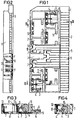
- Fig. 1
- eine teilweise aufgebrochene Draufsicht auf eine Schutzbaugruppe mit Überspannungsableitern,
- Fig. 2
- eine Seitenansicht der Schutzbaugruppe nach Figur 1 mit einem Teilschnitt entlang der Linie II-II in Figur 1,
- Fig. 3
- einen Schnitt durch die Schutzbaugruppe nach Figur 1 entlang der Linie III-III und
- Fig. 4
- einen Schnitt entlang der Linie IV-IV durch die Schutzbaugruppe nach Figur 1.
- Nach den Figuren 1 bis 4 weist ein Gehäuse 1 einer Schutzbaugruppe für einen Verteiler in einem Telekommunikationsnetz Aufnahmekammern 2 für dreipolige Überspannungsableiter 3 mit drahtartigen transversal abstehenden Anschlußbeinchen 4 auf. Die längliche flache Schutzbaugruppe ist entlang ihrer Frontseite 5 mit Steckkontakten 6 versehen, die mit entsprechenden Gegenkontakten des Verteilers kontaktierbar sind.
- Die Steckkontakte 6 sind Bestandteil von Kontaktteilen 7, die sich in einem Boden 8 des Gehäuses 1 in die Richtung der Rückseite der Schutzbaugruppe erstrecken. Die inneren Enden der Kontaktteile 7 sind senkrecht vom Boden 8 hochgebogen. In diesem Abschnitt bilden sie Kontaktklemmen 9 in der Art von Schneidklemmen für isolierte Drähte.
- Auf der Rückseite der Schutzbaugruppe ist ein Erdblech 10 angebracht, von dem aus einstückig verbundene streifenförmige Kontaktteile 7 zu den zugehörigen Anschlußbeinchen 4 verlaufen. Das Erdblech 10 ist auf der Rückseite der Schutzbaugruppe frei zugänglich und kann ohne weiteres mit Erdkontaktfedern des Verteilers kontaktiert werden. Die Kontaktteile 7 des Erdblechs 10 enden ebenfalls in Kontaktklemmen 9, die mit den übrigen Kontaktklemmen 9 fluchten.
- Die Aufnahmekammern 2 sind in zwei Reihen versetzt zueinander angeordnet. In die Aufnahmekammern ragen in der Längsrichtung der Schutzbaugruppe Vorsprünge 11 hinein, die die Überspannungsableiter 3 teilweise überdecken und die an deren Umfang tangential anliegen. Die Vorsprünge 11 sind so angeordnet, daß die Überspannungsableiter 3 mit hochstehenden Anschlußbeinchen 4 darunter geschoben werden können. Danach werden die Anschlußbeinchen 4 in Richtung des Bodens 8 in eine zu diesem parallele Lage geschwenkt. Dabei werden die Anschlußbeinchen 4 in Klemmschlitze 12 der Kontaktklemmen 9 bis zu einer stufenartigen Verengung eingedrückt. Dabei begrenzen Wandteile 13 des Gehäuses 1 die Verschiebbarkeit der Überspannungsableiter 3, so daß diese mit geringem Spiel unter den schräg stehenden Vorsprüngen 11 gehalten werden. Die stufenartige Verengung ist so angeordnet, daß die Anschlußbeinchen 4 in der eingedrückten Stellung annähernd parallel zum Boden 8 des Gehäuses 1 verlaufen.
- Die Kontaktteile 7 sind im Bereich der Steckkontakte 6 u-förmig um die frontseitige Längskante des Gehäuses 1 herumgebogen und bilden so eine Kontaktzone, die eine beidseitige Kontaktierung ermöglicht.
Claims (4)
- Schutzbaugruppe für einen Verteiler in einem Telekommunikationsnetz, vor allem in einer Fernsprechvermittlungsanlage, wobei die Schutzbaugruppe mit Überspannungsableitern (3) bestückbar ist, die transversal abstehende drahtartige Anschlußbeinchen (4) aufweisen und die in Aufnahmekammern (2) eines Gehäuses (1) der Schutzbaugruppe einsetzbar sind, wobei die steckbare flache Schutzbaugruppe mit Kontaktteilen (7) versehen ist, die entlang einer Längskante auf der Frontseite (5) der Schutzbaugruppe als Steckkontakte (6) für entsprechende Gegenkontakte des Verteilers ausgebildet sind und die an ihrem inneren Ende mit den Anschlußbeinchen verbunden sind, und wobei zur Rückseite der Schutzbaugruppe führende Kontaktteile (7) mit einem Erdblech (10) verbunden sind,dadurch gekennzeichnet,daß die inneren Enden der Kontaktteile (7) als Kontaktklemmen (9) in der Art von Schneidklemmen für isolierte Drähte ausgebildet sind, daß die Kontaktklemmen (9) senkrecht zu einem Boden (8) der Schutzbaugruppe hochgebogen sind und daß die Anschlußbeinchen (4) in Klemmschlitze (12) der Kontaktklemmen (9) eindrückbar sind, daß die Anschlußbeinchen (4) annähernd parallel zum Boden der Schutzbaugruppe in die Richtung der Rückseite der Schutzbaugruppe weisen, daß die Kontaktklemmen (9) für alle Anschlußbeinchen (4) des Überspannungsableiters (3) in einer Ebene angeordnet sind, unddaß die dreipoligen Überspannungsableiter (3) partiell unter tangential schräg anliegende Vorsprünge (11) des Gehäuses (1) einsetzbar sind.
- Schutzbaugruppe nach Anspruch 1,
dadurch gekennzeichnet,
daß der Klemmschlitz (12) in seinem mittleren Bereich eine stufenartige Verengung aufweist. - Schutzbaugruppe nach Anspruch 1 oder 2,
dadurch gekennzeichnet,
daß die Aufnahmekammern (2) für die Überspannungsableiter (3) in einer Doppelreihe versetzt zueinander angeordnet sind. - Schutzbaugruppe nach einem der Ansprüche 1 bis 3,
dadurch gekennzeichnet,
daß die Steckkontakte (6) der Kontaktteile um die auf der Frontseite (5) gebildete Längskante des Gehäuses (1) u-förmig herumgebogen sind.
Applications Claiming Priority (2)
| Application Number | Priority Date | Filing Date | Title |
|---|---|---|---|
| DE4008543 | 1990-03-16 | ||
| DE4008543A DE4008543C1 (de) | 1990-03-16 | 1990-03-16 |
Publications (3)
| Publication Number | Publication Date |
|---|---|
| EP0446433A2 EP0446433A2 (de) | 1991-09-18 |
| EP0446433A3 EP0446433A3 (en) | 1992-09-23 |
| EP0446433B1 true EP0446433B1 (de) | 1996-01-17 |
Family
ID=6402408
Family Applications (1)
| Application Number | Title | Priority Date | Filing Date |
|---|---|---|---|
| EP90122890A Expired - Lifetime EP0446433B1 (de) | 1990-03-16 | 1990-11-29 | Schutzbaugruppe für einen Verteiler in einem Telekommunikationsnetz |
Country Status (13)
| Country | Link |
|---|---|
| EP (1) | EP0446433B1 (de) |
| JP (1) | JP2871876B2 (de) |
| AT (1) | ATE133309T1 (de) |
| AU (1) | AU642719B2 (de) |
| DE (2) | DE4008543C1 (de) |
| DK (1) | DK0446433T3 (de) |
| ES (1) | ES2081902T3 (de) |
| FI (1) | FI911295A7 (de) |
| GR (1) | GR3018714T3 (de) |
| IE (1) | IE910888A1 (de) |
| NO (1) | NO911038L (de) |
| PT (1) | PT97037B (de) |
| ZA (1) | ZA911928B (de) |
Families Citing this family (3)
| Publication number | Priority date | Publication date | Assignee | Title |
|---|---|---|---|---|
| WO1997036467A2 (de) * | 1996-03-28 | 1997-10-09 | Siemens Aktiengesellschaft | Schutzbaugruppe für einen verteiler in einer telekommunikationsanlage |
| DE19818477A1 (de) * | 1998-04-24 | 1999-10-28 | Quante Ag | Überspannungsschutzmagazin für eine Einrichtung der Telekommunikationstechnik |
| DE10007173B4 (de) * | 2000-02-17 | 2005-03-03 | CCS Technology, Inc., Wilmington | Steckbare Baugruppe zum Sichern von elektrischen Leitungen in einem Verteiler einer Telekommunikationsanlage |
Family Cites Families (6)
| Publication number | Priority date | Publication date | Assignee | Title |
|---|---|---|---|---|
| US4113340A (en) * | 1977-06-27 | 1978-09-12 | Illinois Tool Works Inc. | Protective electrical device |
| GB2060267A (en) * | 1979-10-08 | 1981-04-29 | Teletechnique Moderne Comp | Cable head with protection for a telephone exchange distributor |
| DE3311459C2 (de) * | 1983-03-29 | 1985-03-14 | Siemens AG, 1000 Berlin und 8000 München | Verteilerleiste mit einer Mehrzahl von den abisolierfreien Anschluß elektrischer Leiter gestattenden Doppelanschlußklemmen |
| EP0208926B1 (de) * | 1985-07-15 | 1990-09-12 | Siemens Aktiengesellschaft | Steckbare Baugruppe mit elektrischen Sicherungselementen für Verteiler |
| FR2608330B1 (fr) * | 1986-12-11 | 1989-03-31 | Carpano & Pons | Module de protection enfichable pour tete de cable de repartiteur |
| DE8903912U1 (de) * | 1989-03-30 | 1989-07-27 | Siemens AG, 1000 Berlin und 8000 München | Sicherungsbaugruppe für einen Verteiler in einer Telekommunikationsanlage |
-
1990
- 1990-03-16 DE DE4008543A patent/DE4008543C1/de not_active Expired - Fee Related
- 1990-11-29 DK DK90122890.8T patent/DK0446433T3/da active
- 1990-11-29 EP EP90122890A patent/EP0446433B1/de not_active Expired - Lifetime
- 1990-11-29 AT AT90122890T patent/ATE133309T1/de not_active IP Right Cessation
- 1990-11-29 ES ES90122890T patent/ES2081902T3/es not_active Expired - Lifetime
- 1990-11-29 DE DE59010074T patent/DE59010074D1/de not_active Expired - Fee Related
-
1991
- 1991-03-14 PT PT97037A patent/PT97037B/pt not_active IP Right Cessation
- 1991-03-15 FI FI911295A patent/FI911295A7/fi not_active Application Discontinuation
- 1991-03-15 NO NO91911038A patent/NO911038L/no unknown
- 1991-03-15 IE IE088891A patent/IE910888A1/en not_active IP Right Cessation
- 1991-03-15 AU AU73523/91A patent/AU642719B2/en not_active Ceased
- 1991-03-15 JP JP3051172A patent/JP2871876B2/ja not_active Expired - Lifetime
- 1991-03-15 ZA ZA911928A patent/ZA911928B/xx unknown
-
1996
- 1996-01-18 GR GR950403693T patent/GR3018714T3/el unknown
Also Published As
| Publication number | Publication date |
|---|---|
| DE59010074D1 (de) | 1996-02-29 |
| ATE133309T1 (de) | 1996-02-15 |
| ES2081902T3 (es) | 1996-03-16 |
| DK0446433T3 (da) | 1996-03-25 |
| PT97037A (pt) | 1993-03-31 |
| JPH04222192A (ja) | 1992-08-12 |
| IE910888A1 (en) | 1991-09-25 |
| ZA911928B (en) | 1991-12-24 |
| AU642719B2 (en) | 1993-10-28 |
| FI911295A0 (fi) | 1991-03-15 |
| JP2871876B2 (ja) | 1999-03-17 |
| NO911038D0 (no) | 1991-03-15 |
| GR3018714T3 (en) | 1996-04-30 |
| DE4008543C1 (de) | 1991-04-18 |
| AU7352391A (en) | 1991-09-19 |
| NO911038L (no) | 1991-09-17 |
| EP0446433A3 (en) | 1992-09-23 |
| EP0446433A2 (de) | 1991-09-18 |
| FI911295L (fi) | 1991-09-17 |
| FI911295A7 (fi) | 1991-09-17 |
| PT97037B (pt) | 1998-10-30 |
Similar Documents
| Publication | Publication Date | Title |
|---|---|---|
| DE69205988T2 (de) | Verbessertes durchverbindungssystem fuer telecommunicationssysteme. | |
| EP0272200B1 (de) | Anschlussleiste für die Fernmeldetechnik | |
| EP0075150A2 (de) | Vorrichtung zur Herstellung eines löt-, schraub- und abisolierfreien Einfach- oder Mehrfachkontaktes an einem Anschlusselement | |
| DE3917270A1 (de) | Anschlussleiste mit ueberspannungsschutz | |
| DE102005042163B3 (de) | Schutzstecker für ein Anschlussmodul | |
| EP0952635B1 (de) | Elektrischer Verbinder | |
| EP0446433B1 (de) | Schutzbaugruppe für einen Verteiler in einem Telekommunikationsnetz | |
| DE102011101201B4 (de) | Verteileranschlussmodul und Verfahren zur Beschaltung eines Verteileranschlussmoduls | |
| DE4042306C2 (de) | Endverzweiger mit Prüfstecker | |
| EP0414043B1 (de) | Verteilerleiste für eine Telekommunkationsanlage | |
| DE3629551C2 (de) | ||
| EP0890205B1 (de) | Verteilervorrichtung für einen verteiler in einer telekommunikationsanlage | |
| DE3625422C2 (de) | ||
| EP0660458B1 (de) | Anschlusseinheit für Telekommunikations- und Datenleitungen | |
| EP0258664A2 (de) | Baugruppe zum Sichern von elektrischen Leitungen in Telekommunikationsanlagen | |
| DE102011016062B4 (de) | Verteileranschlussmodul | |
| DD297286A5 (de) | Schutzeinrichtung fuer einen verteiler in einer telekommunikationsanlage | |
| EP0409109B1 (de) | Verteilereinrichtung für eine Telekommunikationsanlage | |
| DE3921203A1 (de) | Schutzstecker fuer eine verteilerleiste in einer telekommunikationsanlage | |
| DE19755719C2 (de) | Kontakt einer Lötverbindung | |
| EP0890206B1 (de) | Schutzbaugruppe für einen verteiler in einer telekommunikationsanlage | |
| DE3921206C1 (en) | Distribution strip for telephone exchange - has contact springs extending over separating contacts and bent back to rear handling side | |
| DE4007007C2 (de) | ||
| WO1991014299A1 (de) | Kontaktbauteil für einen verteiler in einem telekommunikationsnetz | |
| EP1341280B1 (de) | Überspannungsschutz-Anordnung, insbesondere für Telekommunikations-Einrichtungen Überspannungs-schutz-Modul sowie Erdungsanordnung für eine Trennleiste |
Legal Events
| Date | Code | Title | Description |
|---|---|---|---|
| PUAI | Public reference made under article 153(3) epc to a published international application that has entered the european phase |
Free format text: ORIGINAL CODE: 0009012 |
|
| 17P | Request for examination filed |
Effective date: 19901220 |
|
| AK | Designated contracting states |
Kind code of ref document: A2 Designated state(s): AT BE CH DE DK ES FR GB GR IT LI LU NL SE |
|
| PUAL | Search report despatched |
Free format text: ORIGINAL CODE: 0009013 |
|
| AK | Designated contracting states |
Kind code of ref document: A3 Designated state(s): AT BE CH DE DK ES FR GB GR IT LI LU NL SE |
|
| 17Q | First examination report despatched |
Effective date: 19940718 |
|
| GRAA | (expected) grant |
Free format text: ORIGINAL CODE: 0009210 |
|
| AK | Designated contracting states |
Kind code of ref document: B1 Designated state(s): AT BE CH DE DK ES FR GB GR IT LI LU NL SE |
|
| PG25 | Lapsed in a contracting state [announced via postgrant information from national office to epo] |
Ref country code: GR Free format text: LAPSE BECAUSE OF FAILURE TO SUBMIT A TRANSLATION OF THE DESCRIPTION OR TO PAY THE FEE WITHIN THE PRESCRIBED TIME-LIMIT Effective date: 19960117 |
|
| REF | Corresponds to: |
Ref document number: 133309 Country of ref document: AT Date of ref document: 19960215 Kind code of ref document: T |
|
| REF | Corresponds to: |
Ref document number: 59010074 Country of ref document: DE Date of ref document: 19960229 |
|
| REG | Reference to a national code |
Ref country code: CH Ref legal event code: NV Representative=s name: SIEMENS-ALBIS AKTIENGESELLSCHAFT |
|
| REG | Reference to a national code |
Ref country code: ES Ref legal event code: FG2A Ref document number: 2081902 Country of ref document: ES Kind code of ref document: T3 |
|
| REG | Reference to a national code |
Ref country code: DK Ref legal event code: T3 |
|
| REG | Reference to a national code |
Ref country code: GR Ref legal event code: FG4A Free format text: 3018714 |
|
| ITF | It: translation for a ep patent filed | ||
| GBT | Gb: translation of ep patent filed (gb section 77(6)(a)/1977) |
Effective date: 19960322 |
|
| ET | Fr: translation filed | ||
| PLBE | No opposition filed within time limit |
Free format text: ORIGINAL CODE: 0009261 |
|
| STAA | Information on the status of an ep patent application or granted ep patent |
Free format text: STATUS: NO OPPOSITION FILED WITHIN TIME LIMIT |
|
| PG25 | Lapsed in a contracting state [announced via postgrant information from national office to epo] |
Ref country code: DK Effective date: 19961129 Ref country code: GB Effective date: 19961129 |
|
| REG | Reference to a national code |
Ref country code: DK Ref legal event code: EBP |
|
| PG25 | Lapsed in a contracting state [announced via postgrant information from national office to epo] |
Ref country code: LU Free format text: LAPSE BECAUSE OF NON-PAYMENT OF DUE FEES Effective date: 19961130 Ref country code: CH Effective date: 19961130 Ref country code: SE Effective date: 19961130 Ref country code: LI Effective date: 19961130 |
|
| 26N | No opposition filed | ||
| PG25 | Lapsed in a contracting state [announced via postgrant information from national office to epo] |
Ref country code: NL Effective date: 19970601 |
|
| REG | Reference to a national code |
Ref country code: GR Ref legal event code: MM2A Free format text: 3018714 |
|
| REG | Reference to a national code |
Ref country code: CH Ref legal event code: PL |
|
| GBPC | Gb: european patent ceased through non-payment of renewal fee |
Effective date: 19961129 |
|
| PG25 | Lapsed in a contracting state [announced via postgrant information from national office to epo] |
Ref country code: FR Effective date: 19970731 |
|
| NLV4 | Nl: lapsed or anulled due to non-payment of the annual fee |
Effective date: 19970601 |
|
| EUG | Se: european patent has lapsed |
Ref document number: 90122890.8 |
|
| REG | Reference to a national code |
Ref country code: FR Ref legal event code: ST |
|
| PGFP | Annual fee paid to national office [announced via postgrant information from national office to epo] |
Ref country code: AT Payment date: 20001103 Year of fee payment: 11 |
|
| PGFP | Annual fee paid to national office [announced via postgrant information from national office to epo] |
Ref country code: BE Payment date: 20001127 Year of fee payment: 11 |
|
| PGFP | Annual fee paid to national office [announced via postgrant information from national office to epo] |
Ref country code: ES Payment date: 20001211 Year of fee payment: 11 |
|
| PG25 | Lapsed in a contracting state [announced via postgrant information from national office to epo] |
Ref country code: AT Free format text: LAPSE BECAUSE OF NON-PAYMENT OF DUE FEES Effective date: 20011129 |
|
| PG25 | Lapsed in a contracting state [announced via postgrant information from national office to epo] |
Ref country code: ES Free format text: LAPSE BECAUSE OF NON-PAYMENT OF DUE FEES Effective date: 20011130 Ref country code: BE Free format text: LAPSE BECAUSE OF NON-PAYMENT OF DUE FEES Effective date: 20011130 |
|
| BERE | Be: lapsed |
Owner name: SIEMENS A.G. Effective date: 20011130 |
|
| REG | Reference to a national code |
Ref country code: ES Ref legal event code: FD2A Effective date: 20021213 |
|
| PG25 | Lapsed in a contracting state [announced via postgrant information from national office to epo] |
Ref country code: IT Free format text: LAPSE BECAUSE OF NON-PAYMENT OF DUE FEES;WARNING: LAPSES OF ITALIAN PATENTS WITH EFFECTIVE DATE BEFORE 2007 MAY HAVE OCCURRED AT ANY TIME BEFORE 2007. THE CORRECT EFFECTIVE DATE MAY BE DIFFERENT FROM THE ONE RECORDED. Effective date: 20051129 |
|
| PGFP | Annual fee paid to national office [announced via postgrant information from national office to epo] |
Ref country code: DE Payment date: 20081223 Year of fee payment: 19 |
|
| PG25 | Lapsed in a contracting state [announced via postgrant information from national office to epo] |
Ref country code: DE Free format text: LAPSE BECAUSE OF NON-PAYMENT OF DUE FEES Effective date: 20100601 |