EP0445820B1 - Verfahren zum Herstellen eines dreidimensionalen Nadelspitzenprofils - Google Patents
Verfahren zum Herstellen eines dreidimensionalen Nadelspitzenprofils Download PDFInfo
- Publication number
- EP0445820B1 EP0445820B1 EP91103513A EP91103513A EP0445820B1 EP 0445820 B1 EP0445820 B1 EP 0445820B1 EP 91103513 A EP91103513 A EP 91103513A EP 91103513 A EP91103513 A EP 91103513A EP 0445820 B1 EP0445820 B1 EP 0445820B1
- Authority
- EP
- European Patent Office
- Prior art keywords
- point
- sheet material
- light
- image
- photoresist
- Prior art date
- Legal status (The legal status is an assumption and is not a legal conclusion. Google has not performed a legal analysis and makes no representation as to the accuracy of the status listed.)
- Expired - Lifetime
Links
- 238000000034 method Methods 0.000 title claims description 38
- 239000000463 material Substances 0.000 claims description 28
- 229920002120 photoresistant polymer Polymers 0.000 claims description 19
- 238000005530 etching Methods 0.000 claims description 7
- 238000004519 manufacturing process Methods 0.000 claims description 6
- 230000001747 exhibiting effect Effects 0.000 claims description 3
- 238000004904 shortening Methods 0.000 claims description 2
- 239000002184 metal Substances 0.000 description 10
- 238000001259 photo etching Methods 0.000 description 5
- 238000002360 preparation method Methods 0.000 description 3
- 239000011248 coating agent Substances 0.000 description 2
- 238000000576 coating method Methods 0.000 description 2
- 239000000919 ceramic Substances 0.000 description 1
- 238000007796 conventional method Methods 0.000 description 1
- 238000009940 knitting Methods 0.000 description 1
- 230000035515 penetration Effects 0.000 description 1
- 229920000642 polymer Polymers 0.000 description 1
- 229910001220 stainless steel Inorganic materials 0.000 description 1
- 238000001356 surgical procedure Methods 0.000 description 1
- 239000004753 textile Substances 0.000 description 1
Images
Classifications
-
- B—PERFORMING OPERATIONS; TRANSPORTING
- B21—MECHANICAL METAL-WORKING WITHOUT ESSENTIALLY REMOVING MATERIAL; PUNCHING METAL
- B21G—MAKING NEEDLES, PINS OR NAILS OF METAL
- B21G1/00—Making needles used for performing operations
- B21G1/08—Making needles used for performing operations of hollow needles or needles with hollow end, e.g. hypodermic needles, larding-needles
-
- A—HUMAN NECESSITIES
- A61—MEDICAL OR VETERINARY SCIENCE; HYGIENE
- A61B—DIAGNOSIS; SURGERY; IDENTIFICATION
- A61B17/00—Surgical instruments, devices or methods
- A61B17/04—Surgical instruments, devices or methods for suturing wounds; Holders or packages for needles or suture materials
- A61B17/06—Needles ; Sutures; Needle-suture combinations; Holders or packages for needles or suture materials
- A61B17/06066—Needles, e.g. needle tip configurations
-
- B—PERFORMING OPERATIONS; TRANSPORTING
- B23—MACHINE TOOLS; METAL-WORKING NOT OTHERWISE PROVIDED FOR
- B23P—METAL-WORKING NOT OTHERWISE PROVIDED FOR; COMBINED OPERATIONS; UNIVERSAL MACHINE TOOLS
- B23P15/00—Making specific metal objects by operations not covered by a single other subclass or a group in this subclass
- B23P15/28—Making specific metal objects by operations not covered by a single other subclass or a group in this subclass cutting tools
- B23P15/40—Making specific metal objects by operations not covered by a single other subclass or a group in this subclass cutting tools shearing tools
-
- G—PHYSICS
- G03—PHOTOGRAPHY; CINEMATOGRAPHY; ANALOGOUS TECHNIQUES USING WAVES OTHER THAN OPTICAL WAVES; ELECTROGRAPHY; HOLOGRAPHY
- G03F—PHOTOMECHANICAL PRODUCTION OF TEXTURED OR PATTERNED SURFACES, e.g. FOR PRINTING, FOR PROCESSING OF SEMICONDUCTOR DEVICES; MATERIALS THEREFOR; ORIGINALS THEREFOR; APPARATUS SPECIALLY ADAPTED THEREFOR
- G03F7/00—Photomechanical, e.g. photolithographic, production of textured or patterned surfaces, e.g. printing surfaces; Materials therefor, e.g. comprising photoresists; Apparatus specially adapted therefor
Definitions
- This invention relates to a photochemical process for making a device with a three-dimensionally tapered point suitable for needles, staples and other pointed devices according to the preamble of claim 1.
- U.S. Patents 4,587,202 and 4,777,096 disclose an alternative process for preparing surgical needles without requiring the high degree of manual labor associated with conventional processes.
- a metal sheet exhibiting the properties desired for a surgical needle is first coated on at least one surface with a light-sensitive photoresist, preferably on both the top and bottom surfaces thereof, and then the coated surfaces are exposed to light in the form of an image of a plurality of surgical needles where each needle is shaped with a square blunt end to compensate for lateral etching which occurs during a later etching step.
- the image of the needles is typically prepared by covering the coated metal sheet with a negative or photomask.
- the photomask contains a light-impenetrable mask shaped in the form of the surgical needles, so that when the sheet is exposed to light, an image of the needles is created on the coated surface corresponding to the shape of the light-impenetrable mask.
- the exposed photoresist is removed and unwanted metal not protected by the remaining photoresist is etched away in an etching solution.
- the images of the surgical needles for the top and bottom surfaces of the metal sheet are mirror images of each other precisely superimposed. After removing the photoresist from the needles prepared, the needles can be electropolished, attached to sutures, and then sterilized for surgical applications. This process affords an alternative to the slow mechanical production of surgical needles one at a time, and reduces the manpower and therefore the overall cost of preparing such needles.
- EP-A-185 523 discloses a photoetching process for making surgical needles wherein the photoresist coating which is exposed to light, hardens and the unexposed photoresist is removed.
- the invention is an improved process for preparing a device having a point with a tip, although the process is applicable for the preparation of a plurality of devices simultaneously having not only one point, but also, if desired, two or more points.
- the process is an improvement of the process disclosed in the Borysko patents, which generally disclose coating the top and bottom surfaces of a sheet material exhibiting the properties desired for the device with a light-sensitive photoresist, exposing the photoresist with light through a light-impenetrable mask wherein said mask is in the form of an image of the device shaped with a blunt end at the point to compensate for lateral etching during the etching step, said images for the top and bottom surfaces of the sheet material being mirror images of each other in precise register, removing the exposed photoresist and contacting the treated sheet material with an etchant to remove material not protected by the remaining photoresist.
- the improvement comprises the following steps: a) shortening the length of the image of the point of the device on the top surface of the sheet material relative to the length of the image of said point on the bottom surface thereof so as to offset the images of the point of the device on the top and bottom surfaces of the sheet material relative to each other; and b) exposing with light a portion of the image of the point of the device on the top surface of the sheet material with a V-shaped configuration disposed generally along the perimeter of said point and running substantially parallel to each side of said point to the blunt end of the tip of the point so as to form an apex in close proximity to said blunt end and axially aligned with the longitudinal axis of said point.
- the improved process of this invention enables the skilled artisan to produce a device having a long, three-dimensionally tapered point.
- devices which can be prepared by the process of this invention include needles for the textile industry, such as knitting needles, surgical needles, staples and clips. These pointed devices can easily penetrate tissue or other materials and reduce the risk of tearing tissue or other materials during their intended use. Additionally, the shape and length of the taper can be adjusted by varying the dimensions of the V-shaped configuration and the amount of offset of the top and bottom images of the point.
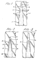
- Fig. 1 is an enlarged plan view of a portion of a photomask image for the top surface of a sheet which can be used in carrying out the process of this invention.
- Fig. 2 is an enlarged plan view of a portion of an alternative photomask image for the top surface a sheet which can be used in carrying out the process of this invention.
- Fig. 3 is an enlarged plan view of the photomask image shown in Fig. 2 superimposed on a portion of a photomask image for the bottom surface of the sheet.
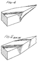
- Fig. 4 is an enlarged perspective view of a portion of a surgical needle which can be prepared by the process of this invention.
- Fig. 5 is an enlarged perspective view of a portion of a surgical needle prepared by the process disclosed in the Borysko patent.
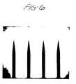
- Fig. 6 is a top view of four surgical needles magnified 100 times prepared by the process of this invention.
- the top and bottom surfaces of the sheet material are the two surfaces which are parallel to the plane of the sheet thereof.
- the point of a device is that portion of the device running generally from the pointed tip to the maximum width of the device, and the length of the point refers to the measured dimension in a direction parallel to the longitudinal axis of the point.
- a taperpoint device e.g. a taperpoint needle, refers generally to those devices whose points taper from the maximum diameter of the device to a sharp, symmetrical tip.
- the device may have two or more points.
- the photoresist-treated sheet material is covered with a photomask to selectively control those areas of the sheet upon which the contact of light is desired.
- the photomask contains a light-impenetrable mask shaped in the form of an image of the pointed device with a blunt end at the tip.
- the photomask for the top surface of the sheet material is the mirror image of the photomask for the bottom surface, and in perfect registry therewith.
- the top and bottom photomasks are not mirror images.
- the length of the image of the point of the device for the top surface of the sheet material is reduced, thereby offsetting the images contained in the photomasks for the bottom and top surfaces of the sheet material relative to each other.
- a V-shaped configuration of light is exposed through the light-impenetrable mask of the image of the pointed device for the top surface of the metal sheet.
- the V-shaped configuration is disposed inside the perimeter of the image of the point. The exposure of light in the V-shaped configuration can be conveniently accomplished when the photomask for the sheet material is prepared. Such a V-shaped configuration is not present in the photomask for the bottom surface of the sheet material.
- Fig. 1 shows a portion of a photomask 10 for the top surface of a sheet.
- the photomask 10 depicts a portion of a needle with a body 11 and a point 12, extending to a blunt end 13 at the tip.
- the V-shaped configuration is provided by a plurality of holes 14 running generally along the perimeter of the point 12 and running parallel to the sides of the point 16 so as to form an apex 15 in close proximity to the blunt end 13 and parallel to the longitudinal axis of the point 12.
- a portion of photomask 17 for the top surface of a metal sheet depicts a needle body 18 and point 19 extending to blunt end 20.
- the V-shaped configuration 23 is depicted as two slits each running parallel to a side of the point 21 thereby forming an apex 22 in close proximity to blunt end 20 and parallel to the longitudinal axis of the point 19.
- Fig. 3 depicts at 24 the photomask of Fig. 2, shown by dotted lines, superimposed on the identical portion of the photomask for the bottom surface of the sheet.
- the length of the point 26 for the bottom surface is longer than the length of the point 19 for the top surface, thereby offsetting the photomask images on each surface relative to each other.
- the shape of the point can be varied significantly to prepare pointed devices with shapes particularly suited for specific applications by varying not only the length, width and other dimensions of the image of the point itself on the top surface of the sheet material, but also the positioning and the dimensions of the V-shaped configuration.
- Figs. 4 and 5 illustrate the dramatic improvement in the shape of a needle point prepared by the process of this invention when compared to a needle point prepared by the process described in the Borysko patents.
- the needle prepared according to the Borysko patent has a rough, chisel-shaped tip with a number of ridges that could potentially tear tissue during operative procedures.
- the photograph shown in Fig. 6 dramatically illustrates the long taper and sharp, symmetrical tip of needles when prepared according to the improved process of this invention.
- the photoresist can be removed from the needle using conventional techniques.
- the needle can then be electropolished, swaged or fastened to one or more sutures if desired, and then sterilized to prepare a needle suitable for numerous surgical applications.
- desired processing steps can be performed for other pointed devices once the photochemical process is completed.
Landscapes
- Health & Medical Sciences (AREA)
- Engineering & Computer Science (AREA)
- Mechanical Engineering (AREA)
- Surgery (AREA)
- Life Sciences & Earth Sciences (AREA)
- Molecular Biology (AREA)
- Veterinary Medicine (AREA)
- Medical Informatics (AREA)
- Biomedical Technology (AREA)
- Animal Behavior & Ethology (AREA)
- General Health & Medical Sciences (AREA)
- Public Health (AREA)
- Heart & Thoracic Surgery (AREA)
- Nuclear Medicine, Radiotherapy & Molecular Imaging (AREA)
- Physics & Mathematics (AREA)
- General Physics & Mathematics (AREA)
- Surgical Instruments (AREA)
- ing And Chemical Polishing (AREA)
- Prostheses (AREA)
Claims (4)
- Verfahren zum Herstellen einer Vorrichtung mit einer Spitze (12, 19) mit einem Spitzenende, bei diesem Verfahren wird eine Materialschicht mit den für die Vorrichtung erwünschten Eigenschaften auf der Oberseite und der Unterseite derselben mit einem lichtempfindlichen Photoresist beschichtet, dadurch gekennzeichnet, daß das Photoresist durch eine lichtundurchlässige Maske (17, 24) belichtet wird, wobei die Maske in Form einer Abbildung der Vorrichtung vorliegt, die mit einem stumpfen Ende (13, 20) am Ende der Spitze geformt ist, um seitliches Ätzen während der Ätzstufe auszugleichen, wobei die Abbildungen der Oberseite und Unterseite der Materialschicht Spiegelbilder voneinander sind, das belichtete Photoresist entfernt wird und die behandelte Materialschicht mit einem Ätzmittel in Berührung gebracht wird, um das Material zu entfernen, das durch das zurückbleibende Photoresist nicht geschützt ist, umfassend die weiteren Verfahrensschritte:a) Verkürzen der Bildlänge der Spitze (19) der Vorrichtung auf der Oberseite der Materialschicht in bezug auf die Bildlänge der Spitze (26) an der Unterseite derselben, um die Abbildungen der Spitze der Vorrichtung auf der Oberseite und der Unterseite der Materialschicht relativ zueinander zu versetzen;b) einen Teil der Abbildung der Spitze (19) der Vorrichtung auf der Oberseite der Materialschicht mit einer V-förmigen Konfiguration zu belichten, die im allgemeinen längs des Umfangs der Spitze (19) angeordnet ist und im wesentlichen parallel zu jeder Seite der Spitze zu dem stumpfen Ende (20) des Endes der Spitze verläuft, um einen Scheitelpunkt (22) in dichter Nähe zu dem stumpfen Ende (20) zu bilden und ihn axial zur Längsachse der Spitze auszurichten.
- Verfahren nach Anspruch 1, wobei die V-förmige Konfiguration in Form einer Mehrzahl von Löchern (14) vorliegt, die sich im allgemeinen parallel zu den Seiten der Spitze (12) erstrecken.
- Verfahren nach Anspruch 1, wobei die V-förmige Konfiguration in Form von zwei schmalen Schlitzen (23) vorliegt, von denen sich jeder Schlitz im allgemeinen parallel zu einer Seite der Spitze erstreckt.
- Verfahren nach Anspruch 1, wobei das Photoresist durch eine lichtundurchlässige Maske in Form einer Abbildung einer Mehrzahl von Zugespitzten Vorrichtungen belichtet wird.
Applications Claiming Priority (2)
| Application Number | Priority Date | Filing Date | Title |
|---|---|---|---|
| US07/490,117 US5057401A (en) | 1990-03-07 | 1990-03-07 | Process for making a device with a three-dimensionally tapered point |
| US490117 | 1990-03-07 |
Publications (2)
| Publication Number | Publication Date |
|---|---|
| EP0445820A1 EP0445820A1 (de) | 1991-09-11 |
| EP0445820B1 true EP0445820B1 (de) | 1995-07-19 |
Family
ID=23946697
Family Applications (1)
| Application Number | Title | Priority Date | Filing Date |
|---|---|---|---|
| EP91103513A Expired - Lifetime EP0445820B1 (de) | 1990-03-07 | 1991-03-07 | Verfahren zum Herstellen eines dreidimensionalen Nadelspitzenprofils |
Country Status (4)
| Country | Link |
|---|---|
| US (1) | US5057401A (de) |
| EP (1) | EP0445820B1 (de) |
| JP (1) | JP2817810B2 (de) |
| DE (1) | DE69111270T2 (de) |
Families Citing this family (27)
| Publication number | Priority date | Publication date | Assignee | Title |
|---|---|---|---|---|
| US5477604A (en) * | 1993-11-01 | 1995-12-26 | Smith; Daniel | Process for manufacturing taper point surgical needles |
| US5792180A (en) * | 1996-01-23 | 1998-08-11 | United States Surgical Corporation | High bend strength surgical needles and surgical incision members and methods of producing same by double sided photoetching |
| US5762811A (en) * | 1996-01-24 | 1998-06-09 | United States Surgical Corporation | One-sided photoetching process for needle fabrication |
| US5693454A (en) * | 1996-01-24 | 1997-12-02 | United States Surgical Corporation | Two-sided photoetching process for needle fabrication |
| DE19607671B4 (de) * | 1996-02-29 | 2004-08-26 | INSTITUT FüR MIKROTECHNIK MAINZ GMBH | Verfahren zur Herstellung optischer Bauelemente mit angekoppelten Lichtwellenleitern und nach diesem Verfahren hergestellte Bauelemente |
| US6565581B1 (en) | 1996-09-16 | 2003-05-20 | Origin Medsystems, Inc. | Apparatus and method for performing an anastomosis |
| US6811555B1 (en) | 1996-09-16 | 2004-11-02 | Origin Medsystems, Inc. | Method and apparatus for performing anastomosis with eversion of tissue edges and joining of exposed intima of the everted tissue |
| US5868763A (en) | 1996-09-16 | 1999-02-09 | Guidant Corporation | Means and methods for performing an anastomosis |
| US5759154A (en) * | 1996-12-23 | 1998-06-02 | C. R. Bard, Inc. | Print mask technique for echogenic enhancement of a medical device |
| US5807317A (en) * | 1997-02-27 | 1998-09-15 | Microtek Medical, Inc. | Trocar with concave cutting surface |
| DE10027060B4 (de) * | 2000-06-05 | 2006-11-30 | Nanosurf Ag | Abtastspitzen,Verfahren zur Herstellung und Verwendung derselben, insbesondere für die Rastersondenmikroskopie |
| US6497994B1 (en) | 2000-06-29 | 2002-12-24 | Ethicon, Inc. | Photolithographic process for the formation of a one-piece needle |
| JP3515493B2 (ja) * | 2000-07-04 | 2004-04-05 | 慎一郎 中山 | 金属棒材の塑性加工方法 |
| US6890338B1 (en) | 2001-02-27 | 2005-05-10 | Origin Medsystems, Inc. | Method and apparatus for performing anastomosis using ring having tines with weak sections |
| WO2003066277A1 (en) * | 2002-02-07 | 2003-08-14 | Browne & Co. Ltd. | Non-symmetrical photo tooling and dual surface etching |
| US7185524B2 (en) * | 2003-08-14 | 2007-03-06 | Tyco Healthcare Group Lp | Grindless surgical needle manufacture |
| US8402889B2 (en) * | 2004-02-03 | 2013-03-26 | Spellbinders Paper Arts Company, Llc | Apertured media embellishing template and system and method using same |
| US7353683B2 (en) * | 2004-02-20 | 2008-04-08 | Tyco Healthcare Group Lp | Surgical needle manufacturing process |
| EP1671585A1 (de) | 2004-12-17 | 2006-06-21 | F. Hoffmann-La Roche Ag | Verfahren zur Herstellung eines Stechelements |
| US7618514B2 (en) * | 2006-02-03 | 2009-11-17 | United Technologies Corporation | Photo-etched EDM electrode |
| US7415858B2 (en) | 2006-02-21 | 2008-08-26 | Tyco Healthcare Group Lp | Grindless surgical needle manufacture |
| WO2013041557A1 (de) * | 2011-09-23 | 2013-03-28 | Roche Diagnostics Gmbh | Verfahren zum maskenätzen eines stechelements |
| US8916863B2 (en) | 2011-09-26 | 2014-12-23 | Panasonic Corporation | Organic thin-film transistor and method of manufacturing organic thin-film transistor |
| WO2013064414A1 (en) * | 2011-11-03 | 2013-05-10 | Novo Nordisk A/S | Process for shaping a needle cannula |
| KR101620837B1 (ko) * | 2014-06-02 | 2016-05-13 | 주식회사 고운세상코스메틱 | 피부 치료용 니들 제조방법 |
| US11020108B2 (en) * | 2015-03-02 | 2021-06-01 | Mound Laser & Photonics Center, Inc. | Needle with rounded edge |
| US11285631B2 (en) | 2015-03-02 | 2022-03-29 | Mound Laser & Photonics Center, Inc. | Chemically sharpening blades |
Family Cites Families (5)
| Publication number | Priority date | Publication date | Assignee | Title |
|---|---|---|---|---|
| GB586003A (en) * | 1944-03-25 | 1947-03-04 | Kodak Ltd | Method of making diaphragms wholly or partly of metal |
| JPS50902A (de) * | 1973-05-04 | 1975-01-08 | ||
| US4587202A (en) * | 1984-12-14 | 1986-05-06 | Ethicon, Inc. | Photoetching process for making surgical needles |
| US4777096A (en) * | 1984-12-14 | 1988-10-11 | Ethicon, Inc. | Sheet containing a plurality of surgical needles |
| US4711800A (en) * | 1985-06-06 | 1987-12-08 | Divincenzo Maureen | Needlecraft with metallic substrate |
-
1990
- 1990-03-07 US US07/490,117 patent/US5057401A/en not_active Expired - Lifetime
-
1991
- 1991-03-06 JP JP3063765A patent/JP2817810B2/ja not_active Expired - Fee Related
- 1991-03-07 EP EP91103513A patent/EP0445820B1/de not_active Expired - Lifetime
- 1991-03-07 DE DE69111270T patent/DE69111270T2/de not_active Expired - Fee Related
Also Published As
| Publication number | Publication date |
|---|---|
| EP0445820A1 (de) | 1991-09-11 |
| DE69111270T2 (de) | 1996-02-08 |
| JP2817810B2 (ja) | 1998-10-30 |
| DE69111270D1 (de) | 1995-08-24 |
| JPH04224038A (ja) | 1992-08-13 |
| US5057401A (en) | 1991-10-15 |
Similar Documents
| Publication | Publication Date | Title |
|---|---|---|
| US5057401A (en) | Process for making a device with a three-dimensionally tapered point | |
| EP0185523B1 (de) | Photoätzverfahren zur Herstellung von chirurgischen Nähnadeln | |
| DE3246677C2 (de) | Künstliche intraokulare Augenlinse | |
| KR100378029B1 (ko) | 스텐트제조방법 | |
| DE69417650T2 (de) | Orthodontisches band | |
| US5762811A (en) | One-sided photoetching process for needle fabrication | |
| KR870000057A (ko) | 안과 수술방법 및 장치 | |
| US5693454A (en) | Two-sided photoetching process for needle fabrication | |
| DE69019702D1 (de) | Verfahren und Vorrichtung zur Stabilisierung des Frequenzabstands zwischen einer Anzahl von Lasern. | |
| AU2017344432C1 (en) | Surgical instrument having a surface texture | |
| DE3228352A1 (de) | Intraokulare und extraokulare linsenkonstruktion und verfahren zur herstellung einer solchen linse | |
| CA2351797A1 (en) | A photolithographic process for the formation of a one-piece needle | |
| EP0962306A3 (de) | Vorrichtung und Verfahren zum Verschweissen von Folienmaterial | |
| JP3676328B2 (ja) | ホトレジストパターンの評価方法 | |
| KR20000013303A (ko) | 분할 노광방법과 분할 노광마스크 | |
| JP3178266B2 (ja) | フラット型シャドウマスクの製造方法及びフラット型シャドウマスク用枚葉状金属板 | |
| DE59609917D1 (de) | Verfahren zum Herstellen und präzisen Positionieren von optischen Mikrolinsen auf den Enden von Fasern und Lasern | |
| JP2006321243A (ja) | コーティングを施されたスクリーン片を備えたスクリーン印刷版およびそのスクリーン印刷版を製造する方法 | |
| DE69029503D1 (de) | Aperturenmuster-Flachdruckplatte zur Herstellung einer Schattenmaske und Verfahren zur Herstellung dieser Maske | |
| JPH0728523U (ja) | 眼手術用マーカ | |
| KR0167241B1 (ko) | 마스크와 노광장비를 이용한 반도체 소자의 주변 노광방법 | |
| JPS61150337A (ja) | 半導体装置の製造方法 | |
| JPH064348Y2 (ja) | フォトマスク原板 | |
| BR112019003651B1 (pt) | Fórceps cirúrgico e método de formar uma superfície texturizada em um fórceps cirúrgico | |
| JPH11329228A (ja) | シャドウマスクの製造方法 |
Legal Events
| Date | Code | Title | Description |
|---|---|---|---|
| PUAI | Public reference made under article 153(3) epc to a published international application that has entered the european phase |
Free format text: ORIGINAL CODE: 0009012 |
|
| AK | Designated contracting states |
Kind code of ref document: A1 Designated state(s): CH DE GB LI |
|
| 17P | Request for examination filed |
Effective date: 19920302 |
|
| 17Q | First examination report despatched |
Effective date: 19940412 |
|
| GRAA | (expected) grant |
Free format text: ORIGINAL CODE: 0009210 |
|
| AK | Designated contracting states |
Kind code of ref document: B1 Designated state(s): CH DE GB LI |
|
| REF | Corresponds to: |
Ref document number: 69111270 Country of ref document: DE Date of ref document: 19950824 |
|
| PLBE | No opposition filed within time limit |
Free format text: ORIGINAL CODE: 0009261 |
|
| STAA | Information on the status of an ep patent application or granted ep patent |
Free format text: STATUS: NO OPPOSITION FILED WITHIN TIME LIMIT |
|
| 26N | No opposition filed | ||
| REG | Reference to a national code |
Ref country code: GB Ref legal event code: IF02 |
|
| PGFP | Annual fee paid to national office [announced via postgrant information from national office to epo] |
Ref country code: DE Payment date: 20070301 Year of fee payment: 17 Ref country code: CH Payment date: 20070301 Year of fee payment: 17 |
|
| PGFP | Annual fee paid to national office [announced via postgrant information from national office to epo] |
Ref country code: GB Payment date: 20070307 Year of fee payment: 17 |
|
| REG | Reference to a national code |
Ref country code: CH Ref legal event code: PFA Owner name: ETHICON, INC. Free format text: ETHICON, INC.#U.S. ROUTE NO. 22#SOMERVILLE/NJ (US) -TRANSFER TO- ETHICON, INC.#U.S. ROUTE NO. 22#SOMERVILLE/NJ (US) |
|
| REG | Reference to a national code |
Ref country code: CH Ref legal event code: PL |
|
| GBPC | Gb: european patent ceased through non-payment of renewal fee |
Effective date: 20080307 |
|
| PG25 | Lapsed in a contracting state [announced via postgrant information from national office to epo] |
Ref country code: LI Free format text: LAPSE BECAUSE OF NON-PAYMENT OF DUE FEES Effective date: 20080331 Ref country code: CH Free format text: LAPSE BECAUSE OF NON-PAYMENT OF DUE FEES Effective date: 20080331 Ref country code: DE Free format text: LAPSE BECAUSE OF NON-PAYMENT OF DUE FEES Effective date: 20081001 |
|
| PG25 | Lapsed in a contracting state [announced via postgrant information from national office to epo] |
Ref country code: GB Free format text: LAPSE BECAUSE OF NON-PAYMENT OF DUE FEES Effective date: 20080307 |