EP0445635B1 - Öffnungs- und Schliessmechanismus - Google Patents
Öffnungs- und Schliessmechanismus Download PDFInfo
- Publication number
- EP0445635B1 EP0445635B1 EP91102885A EP91102885A EP0445635B1 EP 0445635 B1 EP0445635 B1 EP 0445635B1 EP 91102885 A EP91102885 A EP 91102885A EP 91102885 A EP91102885 A EP 91102885A EP 0445635 B1 EP0445635 B1 EP 0445635B1
- Authority
- EP
- European Patent Office
- Prior art keywords
- opening
- plate
- pop
- shaft
- closing
- Prior art date
- Legal status (The legal status is an assumption and is not a legal conclusion. Google has not performed a legal analysis and makes no representation as to the accuracy of the status listed.)
- Expired - Lifetime
Links
Images
Classifications
-
- E—FIXED CONSTRUCTIONS
- E05—LOCKS; KEYS; WINDOW OR DOOR FITTINGS; SAFES
- E05D—HINGES OR SUSPENSION DEVICES FOR DOORS, WINDOWS OR WINGS
- E05D11/00—Additional features or accessories of hinges
- E05D11/08—Friction devices between relatively-movable hinge parts
- E05D11/087—Friction devices between relatively-movable hinge parts with substantially axial friction, e.g. friction disks
-
- E—FIXED CONSTRUCTIONS
- E05—LOCKS; KEYS; WINDOW OR DOOR FITTINGS; SAFES
- E05F—DEVICES FOR MOVING WINGS INTO OPEN OR CLOSED POSITION; CHECKS FOR WINGS; WING FITTINGS NOT OTHERWISE PROVIDED FOR, CONCERNED WITH THE FUNCTIONING OF THE WING
- E05F1/00—Closers or openers for wings, not otherwise provided for in this subclass
- E05F1/08—Closers or openers for wings, not otherwise provided for in this subclass spring-actuated, e.g. for horizontally sliding wings
- E05F1/10—Closers or openers for wings, not otherwise provided for in this subclass spring-actuated, e.g. for horizontally sliding wings for swinging wings, e.g. counterbalance
- E05F1/12—Mechanisms in the shape of hinges or pivots, operated by springs
- E05F1/1207—Mechanisms in the shape of hinges or pivots, operated by springs with a coil spring parallel with the pivot axis
- E05F1/1215—Mechanisms in the shape of hinges or pivots, operated by springs with a coil spring parallel with the pivot axis with a canted-coil torsion spring
-
- E—FIXED CONSTRUCTIONS
- E05—LOCKS; KEYS; WINDOW OR DOOR FITTINGS; SAFES
- E05Y—INDEXING SCHEME ASSOCIATED WITH SUBCLASSES E05D AND E05F, RELATING TO CONSTRUCTION ELEMENTS, ELECTRIC CONTROL, POWER SUPPLY, POWER SIGNAL OR TRANSMISSION, USER INTERFACES, MOUNTING OR COUPLING, DETAILS, ACCESSORIES, AUXILIARY OPERATIONS NOT OTHERWISE PROVIDED FOR, APPLICATION THEREOF
- E05Y2900/00—Application of doors, windows, wings or fittings thereof
- E05Y2900/20—Application of doors, windows, wings or fittings thereof for furniture, e.g. cabinets
-
- E—FIXED CONSTRUCTIONS
- E05—LOCKS; KEYS; WINDOW OR DOOR FITTINGS; SAFES
- E05Y—INDEXING SCHEME ASSOCIATED WITH SUBCLASSES E05D AND E05F, RELATING TO CONSTRUCTION ELEMENTS, ELECTRIC CONTROL, POWER SUPPLY, POWER SIGNAL OR TRANSMISSION, USER INTERFACES, MOUNTING OR COUPLING, DETAILS, ACCESSORIES, AUXILIARY OPERATIONS NOT OTHERWISE PROVIDED FOR, APPLICATION THEREOF
- E05Y2999/00—Subject-matter not otherwise provided for in this subclass
Definitions
- This invention relates to an opening/closing mechanism in an apparatus having a main body and an opening/closing portion.
- the arrangement is such that the opening/closing portion opens slightly when this portion is released. Further, it is so arranged that it is not possible to close the opening/closing portion completely unless this portion is pressed, when the opening/closing portion is closed. This arrangement prevents the opening/closing portion and the main body from striking.
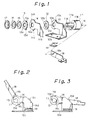
- a conventional apparatus of this kind thus constructed employs an opening/closing mechanism shown in Fig. 11.
- a base 1 shown in Fig. 11 is attached to the main body of an apparatus.
- a shaft 2 is supported by the base 1 so as to turn freely. Further, the opening/closing portion of the apparatus, a cam 3, and a coil spring 4 are attached to the shaft 2.
- the shaft 2 and cam 3 rotate in the direction of arrow A when the opening/closing portion is opened, and in the direction of arrow B when the opening/closing portion is closed.
- the opening/closing portion pops up by opening slightly at this time.
- the coil spring 4 limits the turning of the shaft so that the position of the opening/closing portion is maintained.
- the coil spring 4 is used for maintaining the position of the opening/closing portion and getting pop-up action. For this reason, there is a limitation upon the placement of the spring and the wire diameter, and it is difficult to reduce the size of the mechanism.
- a holding device for a cover at an electrical apparatus has been described (CH-A-543 219).
- This cover is pivotally mounted on an axis parallel to the axis of a wall of the apparatus.
- at least two pins are run on bearings of the friction type located on said cover.
- the disadvantage of this holding device lies in the fact that the friction type bearings consist of saucer springs the friction forces of which cannot be adjusted exactly.
- the problem to be solved by the present invention is to provide an easily manufactured opening/closing mechanism of small size and with stable friction forces.
- an opening/closing mechanism comprising a base attached to a main body of an apparatus; an arm attached to an opening/closing portion of the appratus and axially supported on the base so as to turn freely; a rotary plate which turnes together with the arm and which has a projection; a pop-up plate having an engaging portion, wherein when the opening/closing portion is closed up to a prescribed position, the engaging portion engages with the projection of the rotary plate so that at a further displacement of the opening/closing portion to its final closed position the pop-up plate turnes together with the rotary plate; and a resilient member provided between the pop-up plate and the base and compressed by turning of the pop-up plate, wherein the pop-up plate and the rotary plate are turned by this compressive force.
- the projection formed on the rotary plate in the opening/closing mechanism of the invention engages the engaging portion of the pop-up plate.
- the pop-up plate turns together with the rotary plate and is stopped at a prescribed position.
- a coil spring is not used, and the leaf spring specifically for the pop-up plate is arranged at a location remote from the shaft.
- both the second rotary plate and pop-up plate are constituted by plate members.
- the arrangement according to the first embodiment is such that a small force is applied to the pop-up plate by the leaf spring at all times, thereby making it possible to prevent the occurrence of gap among the parts.
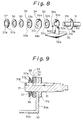
- numeral 10 denotes a base attached to a main body 20 of an apparatus shown in Figs. 5 to 7.
- the base 10 has a mounting portion 10a attached to the main body 20, and a support portion 10b vertically upstanding form the mounting portion 10a and having a hole 10c at its center. Further, the support portion 10b has a stopper 10d which contacts a pop-up plate (described later) and is formed at the side face of the support portion 10b.
- Numeral 11 denotes a shaft comprising a small-diameter portion 11a which matches the hole 10c, a large-diameter portion 11b, and a rectangular mounting portion 11c projecting from the end face of the large-diameter portion 11b.
- a linear groove 11d is formed at the outer periphery of the small-diameter portion 11a of shaft 11 and in the axial direction of the shaft.
- Numerals 12, 13 denote first and second rotary plates each having the shape of a planar disk and holes 12a, 13a formed at the center thereof.
- Inwardly directed projections 12b, 13b matching the groove 11d of shaft 11 are provided at the inner peripheral portions of the holes 12a, 13a, respectively.
- a projection 13d is provided at the outer peripheral portion of the second rotary plate 13 and bends to one side of the plate.
- Numeral 14 denotes a pop-up plate having a hole 14a which matches the small-diameter portion 11a, first and second engaging portions 14b, 14c provided on its outer peripheral portion with a predetermined spacing between them, and an urging portion 14d projecting in the direction of the mounting portion 10a of base 10.
- Numerals 15, 16 denote ring-shaped cup springs
- numeral 17 denotes a push nut attached to the tip of the small-diameter portion 11a of shaft 11.
- Numeral 18 denotes an arm attached to an opening/closing portion 21 such as the display portion of the apparatus shown in Figs. 5 to 7.
- the arm 18 has a hole 18a which matches the mounting portion 11c of shaft 11.
- Numeral 19 denotes a leaf spring serving as a resilient member.
- the leaf spring is fixed on the mounting portion 10a of base 10 and is disposed between the mounting portion 10a and the urging portion 14d of pop-up plate 14.
- the first and second rotary plates 12, 13 turn together with the shaft 11 since the projections 12b, 13b thereof are engaged with the groove 11d of shaft 11.
- the first and second rotary plates 12, 13, the pop-up plate 14 and the support portion 10b of base 10 are alternately disposed and held in pressured contact by the cup springs 15, 16.
- the projection 13d provided on the second rotary plate 13 is so arranged as to come into abutting contact with each of the engaging portions 14b, 14c of the pop-up plate 14 when the second rotary plate 13 is turned through a predetermined angle.
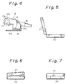
- the arm 18 is attached to the shaft 11 in such a manner that the opening/closing portion 21 of the apparatus attains a widely open state, as shown in Fig. 5.
- the projection 13d of the second rotary plate 13 is in contact with the second engaging portion 14c of pop-up plate 14, as shown in Fig. 2.
- the arm 18 rotates in the clockwise direction in the drawing, as illustrated in Fig. 3, and this is accompanied by rotation of the rotary plate 13 until its projection 13d abuts against the first engaging portion 14b of pop-up plate 14.
- the opening/closing portion 21 assumes a slightly open state, as illustrated in Fig. 6.
- the pop-up plate 14 is rotated counter-clockwise by the force of the leaf spring 19, and the second rotary plate 13, whose projection 13d is engaging with the first projection 14b of the pop-up plate, also rotates in the counter-clockwise direction.
- the arm 18 also rotates counter-clockwise and becomes the state shown in Fig. 3, and the opening/closing portion 21 becomes the state shown in Fig. 6.
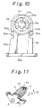
- the opening/closing mechanism has a pop-up mechanism for opening the opening/closing portion slightly from the completely closed state and a tilt mechanism for fixing the opening/closing portion at any angle. It is possible to divide the pop-up mechanism and tilt mechanism.
- Numeral 30 denotes a base attached to the main body of an apparatus such as a personal computer.
- the base 30 has a mounting portion 30a attached to the main body of the apparatus, and a support portion 30b vertically upstanding from the mounting portion 30a and having a hole 30c at its center. Further, stoppers 30d, 30e are provided at the side face of the support portion 30b and contact a fixed plate (described later).
- Numeral 31 denotes a shaft comprising a small-diameter portion 31a which matches the hole 30c, a disk-shaped large-diameter portion 31b having a diameter larger than that of portion 31a, and a mounting portion 31c attached to an opening/closing portion of the apparatus via an arm or the like. Further, a linear groove 31d is provided at the outer periphery of the small-diameter portion 31a and in the axial direction of the shaft.
- Numerals 32, 33 denote first and second rotary plates each having the shape of a planar disk and having holes 32a, 33a at the center thereof.
- Inwardly directed projections 32b, 33b matching the groove 31d of shaft 31 are respectively provided at the inner peripheral portions of the holes 32a, 33a.
- Numeral 34 denotes a fixed plate in the shape of a planar disk having a hole 5a which matches the small-diameter portion 31a, and engaging portions 34b, 34c provided on the outer peripheral portion for engaging with the stoppers 30d, 30e of the base 30.
- Numerals 35, 36 denote ring-shaped cup springs.
- Numeral 37 denotes a push nut comprising a ring-shaped rim portion 37a, and a plurality of locking pieces 37b projecting toward the center of the nut from the rim portion 37a.
- the small-diameter portion 31a of the shaft 31 is passed through the hole 30c of base 30, and the above mentioned parts are mounted on the small-diameter portion 31a in the order of the first rotary plate 32, fixed plate 34, second rotary plate 33, cup springs 35, 36 and push nut 37.
- the first and second rotary plates 32, 33 are mounted in such a manner that their projections 32b, 33b fit into the groove 31d of shaft 31, and therefore the rotary plates turn together with the shaft 31.
- the fixed plate 34 is mounted in such a manner that its engaging portions 34b, 34c abut against the respective stoppers 30d, 30e of the base 30.
- the push nut 37 is fitted onto the outer Periphery of the small-diameter portion 31a by being pushed from the end portion of the small-diameter portion 31a of shaft 31.
- the cup spring 36 is urged by the rim portion 37a of the push nut, and the locking portion 37b of the push nut bites into the outer periphery of the small-diameter portion 31a, whereby the push nut is fixedly attached on the small-diameter portion 31a.
- the fixed plate 34 is arranged between the first and second rotary plates 32, 33, and these plates are sandwiched between the support portion 30b of base 30 and the push nut 37 to be brought into contact by a constant force.
Landscapes
- Engineering & Computer Science (AREA)
- Mechanical Engineering (AREA)
- Pivots And Pivotal Connections (AREA)
Claims (5)
- Öffnungs- und Schließmechanismus, bestehend aus:1.1 einem mit einem Hauptgehäuse (20) eines Geräts befestigten Basisteil (10);1.2 einer von dem besagten Basisteil (10) drehbar gelagerten Welle (11);1.3 einer sich mit besagter Welle (11) zusammen drehenden Drehplatte (12, 13);gekennzeichnet durch1.4 einen an dem Öffnungs- und Schließteil (21) des besagten Geräts angebrachten und sich zusammen mit besagter Welle (11) drehenden Arm (18);1.5 besagte Drehplatte (12, 13) mit einer Nase (13d);1.6 eine durch besagte Welle (11) drehbar gelagerte und einen Eingriffsteil (14b, 14c) aufweisende Anschlagplatte (14), wobei besagtes Öffnungs- und Schließteil (21) in einer vorgeschriebenen Lage geschlossen ist, das Eingriffsteil (14c) mit der Nase (13d) der Drehplattte (12, 13) in Eingriff steht, so daß besagte Anschlagplatte (14) sich mit besagter Drehplatte (13) zusammen dreht; und1.7 ein zwischen besagter Anschlagplatte (14) und besagtem Basisteil (10) vorgesehenes Federglied (19), welches durch Drehen der besagten Anschlagplatte (14) zusammengepreßt wird, wobei besagtes Öffnungs- und Schließteil (21) freigegeben wird, die besagte Drehplatte (13) mit der Anschlagplatte (14) durch eine Druckkraft zusammengepreßt wird und dabei das Öffnungs- und Schließteil (21) bis zu einer vorgegebenen Lage geöffnet wird.
- Öffnungs- und Schließmechanismus nach Anspruch 1, dadurch gekennzeichnet, daß die Welle (11) eine lineare Kerbe (11d) aufweist, welche am äußeren Umfang derselben angeformt ist, und wobei besagte Drehplatte (12, 13) eine nach innen gerichtete Nase (13b) aufweist, welche mit besagter Kerbe der besagten Welle (11) in Eingriff steht.
- Öffnungs- und Schließmechanismus nach Anspruch 1, dadurch gekennzeichnet, daß das Federglied (19) eine Blattfeder aufweist.
- Öffnungs- und Schließmechanismus nach Anspruch 1, dadurch gekennzeichnet, daß das Basisteil (10) einen Anschlag (10d) aufweist, welcher die Anschlagplatte (14) berührt.
- Öffnungs- und Schließmechanismus nach Anspruch 1, gekennzeichnet durch weiterhin vorgesehene, von der Welle (11) gehaltene Tellerfedern (15, 16) und einen am Ende der Welle (11) durch den Druck besagter Tellerfedern zum Fixieren der Drehplatte (12, 13), der Anschlagplatte (14) und des Basisteils (10) angebrachten Federring (17).
Applications Claiming Priority (4)
| Application Number | Priority Date | Filing Date | Title |
|---|---|---|---|
| JP2055898A JPH03257276A (ja) | 1990-03-07 | 1990-03-07 | ホップアップ機構 |
| JP55898/90 | 1990-03-07 | ||
| JP31070/90U | 1990-03-28 | ||
| JP3107090U JPH0439321U (de) | 1990-03-28 | 1990-03-28 |
Publications (2)
| Publication Number | Publication Date |
|---|---|
| EP0445635A1 EP0445635A1 (de) | 1991-09-11 |
| EP0445635B1 true EP0445635B1 (de) | 1995-08-16 |
Family
ID=26369520
Family Applications (1)
| Application Number | Title | Priority Date | Filing Date |
|---|---|---|---|
| EP91102885A Expired - Lifetime EP0445635B1 (de) | 1990-03-07 | 1991-02-28 | Öffnungs- und Schliessmechanismus |
Country Status (3)
| Country | Link |
|---|---|
| US (1) | US5109570A (de) |
| EP (1) | EP0445635B1 (de) |
| DE (1) | DE69112102T2 (de) |
Families Citing this family (54)
| Publication number | Priority date | Publication date | Assignee | Title |
|---|---|---|---|---|
| US5217316A (en) * | 1990-10-12 | 1993-06-08 | Nhk Spring Co., Ltd. | Slow-acting rotation shaft device |
| US5379182A (en) * | 1991-11-29 | 1995-01-03 | Nec Corporation | Hinged display panel with outer cover and display panel unit separately connected to an inner cover and information machine including the same |
| JPH05307425A (ja) * | 1992-04-28 | 1993-11-19 | Brother Ind Ltd | 表示器支持装置 |
| GB2266920A (en) * | 1992-05-12 | 1993-11-17 | Wang Tsan Shou | Hinging device for casing. |
| US5269047A (en) * | 1992-06-10 | 1993-12-14 | Lu Sheng N | Hinge device for casings |
| CN2130955Y (zh) * | 1992-07-28 | 1993-04-28 | 陈桂榕 | 枢轴 |
| US5406678A (en) * | 1993-07-22 | 1995-04-18 | General Clutch Corporation | Friction hinge |
| JP3662353B2 (ja) * | 1996-08-05 | 2005-06-22 | 加藤電機株式会社 | チルトヒンジ |
| KR100220668B1 (ko) * | 1996-10-16 | 1999-09-15 | 윤종용 | 휴대용 컴퓨터 |
| US5873847A (en) * | 1996-11-14 | 1999-02-23 | Lenjoy Engineering, Inc. | Articulated splints and goniometric hinge for the same |
| JP3721244B2 (ja) * | 1997-05-15 | 2005-11-30 | 加藤電機株式会社 | 開閉体の開閉装置 |
| JP3798899B2 (ja) * | 1998-01-27 | 2006-07-19 | 加藤電機株式会社 | チルトヒンジ |
| US5970580A (en) * | 1998-03-23 | 1999-10-26 | Katoh Electrical Machinery Co., Ltd. | Tilt hinge for office automation equipment |
| US6018847A (en) * | 1998-07-02 | 2000-02-01 | Lu; Sheng-Nan | Hinge axle device for a LCD monitor |
| KR200196906Y1 (ko) * | 1998-07-11 | 2000-10-02 | 정기근 | 힌지장치 |
| TW506549U (en) * | 1999-07-22 | 2002-10-11 | Kato Electric & Machinary Co | Slanted hinge |
| WO2001014671A1 (en) * | 1999-08-25 | 2001-03-01 | Southco, Inc. | Friction hinge |
| KR200233484Y1 (ko) * | 2001-02-22 | 2001-09-28 | 피케이텍시스템 주식회사 | 힌지 장치 |
| US6481057B2 (en) * | 2001-03-20 | 2002-11-19 | Wen-Chi Lin | Positioning hinge adapted between a computer main body and a display |
| KR100727384B1 (ko) * | 2001-09-11 | 2007-06-12 | 삼성전자주식회사 | 힌지장치 |
| JP2003174495A (ja) * | 2001-09-28 | 2003-06-20 | Nec Corp | 折り畳み式携帯情報端末 |
| AU2002354507A1 (en) * | 2001-12-24 | 2003-07-15 | Lg Electronics Inc. | Hinge assembly for flat panel display appliance |
| CN1279418C (zh) * | 2001-12-24 | 2006-10-11 | Lg电子株式会社 | 用于平板显示器设备的铰接组件 |
| CN1297863C (zh) * | 2001-12-24 | 2007-01-31 | Lg电子株式会社 | 用于平板显示器设备的铰接组件 |
| KR100451803B1 (ko) * | 2001-12-27 | 2004-10-08 | 엘지전자 주식회사 | 평면 영상 표시 기기의 힌지 구조 |
| KR100463524B1 (ko) * | 2002-05-29 | 2004-12-29 | 엘지전자 주식회사 | 영상표시기기용 힌지어셈블리 |
| US6581893B1 (en) * | 2002-09-05 | 2003-06-24 | Shin Zu Shing Co., Ltd. | Stand for an LCD monitor |
| US6748625B2 (en) * | 2002-11-12 | 2004-06-15 | Shin Zu Shing Co., Ltd. | Notebook computer hinge with spring opener |
| JP2004197862A (ja) * | 2002-12-19 | 2004-07-15 | Strawberry Corporation | ヒンジ装置並びにヒンジ装置を用いた電子機器 |
| JP2005106139A (ja) * | 2003-09-29 | 2005-04-21 | Kato Electrical Mach Co Ltd | チルトヒンジ |
| US20050081334A1 (en) * | 2003-10-15 | 2005-04-21 | Tai Wen H. | Hinge structure |
| JP4397225B2 (ja) * | 2003-12-04 | 2010-01-13 | 日本発條株式会社 | ヒンジ装置 |
| CN2691216Y (zh) * | 2004-02-03 | 2005-04-06 | 安普新股份有限公司 | 枢钮结构 |
| WO2005117637A1 (en) * | 2004-06-01 | 2005-12-15 | Louis Vuitton Malletier | Baggage having a self-locking hinge |
| CN2736889Y (zh) * | 2004-07-17 | 2005-10-26 | 鸿富锦精密工业(深圳)有限公司 | 便携式光盘播放器 |
| US7089628B2 (en) * | 2004-09-16 | 2006-08-15 | Quanta Computer, Inc. | Hinge design for a computer |
| TWI274533B (en) * | 2005-05-24 | 2007-02-21 | Benq Corp | Electric device and position mechanism thereof |
| US20070101543A1 (en) * | 2005-11-04 | 2007-05-10 | Shin Zu Shing Co., Ltd. | Hinge |
| CN100467891C (zh) * | 2005-12-01 | 2009-03-11 | 鸿富锦精密工业(深圳)有限公司 | 铰链装置 |
| TWM292885U (en) * | 2005-12-30 | 2006-06-21 | Shin Zu Shing Co Ltd | Pivot |
| JP2007193245A (ja) * | 2006-01-23 | 2007-08-02 | Funai Electric Co Ltd | 表示画面支持機構 |
| TWM296586U (en) * | 2006-01-26 | 2006-08-21 | Jarllytec Co Ltd | Structure of rotary shaft with automatic latching function |
| US20090119879A1 (en) * | 2006-05-24 | 2009-05-14 | Pleo Originals, Llc | Hinge pin |
| TW200820872A (en) * | 2006-10-25 | 2008-05-01 | Compal Electronics Inc | Pivot-jointed structure of a portable electronic device |
| US20080120808A1 (en) * | 2006-11-29 | 2008-05-29 | Ting-Hsien Wang | Limited travel hinge |
| US7814620B2 (en) * | 2008-01-29 | 2010-10-19 | Cheng Uei Precision Industry Co., Ltd. | Hinge |
| US20090188080A1 (en) * | 2008-01-29 | 2009-07-30 | Cheng Uei Precision Industry Co., Ltd. | Hinge |
| CN101614237A (zh) * | 2008-06-27 | 2009-12-30 | 鸿富锦精密工业(深圳)有限公司 | 铰链结构 |
| CN101666352B (zh) * | 2008-09-03 | 2012-08-29 | 鸿富锦精密工业(深圳)有限公司 | 铰链结构 |
| CN101684837B (zh) * | 2008-09-22 | 2012-10-10 | 鸿富锦精密工业(深圳)有限公司 | 铰链结构 |
| JP5309380B2 (ja) * | 2009-05-29 | 2013-10-09 | 日本発條株式会社 | ヒンジ装置及びヒンジ装置用ブラケット |
| BR112012029623A2 (pt) * | 2010-05-21 | 2016-08-02 | Johnson Controls Tech Co | conjunto de dobradiça para componente de acabamento em interior de veículo |
| CN103339392A (zh) * | 2011-02-04 | 2013-10-02 | 日本发条株式会社 | 铰链装置 |
| US8261412B1 (en) * | 2011-04-27 | 2012-09-11 | Leohab Enterprise Co., Ltd. | Hinge assembly and foldable electronic device using the same |
Family Cites Families (12)
| Publication number | Priority date | Publication date | Assignee | Title |
|---|---|---|---|---|
| US2183210A (en) * | 1937-04-27 | 1939-12-12 | Nat Lock Co | Hinge |
| US3117827A (en) * | 1962-06-01 | 1964-01-14 | Oscar C Rixson Co | Thrust bearing |
| CH543219A (de) * | 1972-08-31 | 1973-10-15 | Siemens Ag Albis | Haltevorrichtung für einen Deckel an einem elektronischen Gerät |
| DE2436038C3 (de) * | 1974-07-26 | 1980-08-28 | Braun Ag, 6000 Frankfurt | Vorrichtung zum Arretieren einer Abdeckhaube für Rundfunk- und Phonogeräte |
| DE2642508C2 (de) * | 1976-09-22 | 1978-10-26 | Philips Patentverwaltung Gmbh, 2000 Hamburg | Fernsehempfangsgehäuse und Verwendung eines derartigen Gehäuses |
| DD156046A1 (de) * | 1981-01-30 | 1982-07-21 | Ulrich Naumann | Scharnier fuer abdeckungen von geraeten und gehaeusen |
| US4408799A (en) * | 1981-06-25 | 1983-10-11 | Hoover Universal, Inc. | Infinitely variable seat back recliner |
| JPS60127888A (ja) * | 1983-12-15 | 1985-07-08 | Citizen Watch Co Ltd | 液晶表示装置 |
| US4575169A (en) * | 1985-02-06 | 1986-03-11 | Porta Systems Corp. | Telephone building entrance terminal |
| US4730364A (en) * | 1985-10-29 | 1988-03-15 | Bondwell Holding Ltd. | Data processor flush hinge assembly |
| US4709121A (en) * | 1985-12-23 | 1987-11-24 | General Dynamics, Pomona Division | Hinge seal |
| US5031270A (en) * | 1990-03-15 | 1991-07-16 | Simpson Lee | Friction hinge |
-
1991
- 1991-02-28 EP EP91102885A patent/EP0445635B1/de not_active Expired - Lifetime
- 1991-02-28 DE DE69112102T patent/DE69112102T2/de not_active Expired - Fee Related
- 1991-03-06 US US07/665,420 patent/US5109570A/en not_active Expired - Lifetime
Also Published As
| Publication number | Publication date |
|---|---|
| EP0445635A1 (de) | 1991-09-11 |
| DE69112102D1 (de) | 1995-09-21 |
| US5109570A (en) | 1992-05-05 |
| DE69112102T2 (de) | 1996-04-04 |
Similar Documents
| Publication | Publication Date | Title |
|---|---|---|
| EP0445635B1 (de) | Öffnungs- und Schliessmechanismus | |
| US5195213A (en) | Hinge device for coupling rotatable member to another member | |
| US6618903B2 (en) | Hinge device | |
| CN101625009B (zh) | 铰链结构 | |
| TWI620879B (zh) | Opening and closing device and terminal machine using the same | |
| US8141207B2 (en) | Two-axis hinge device and mobile terminal apparatus | |
| US5738321A (en) | Magnetic recording and reproducing device | |
| CN101660566A (zh) | 铰链结构 | |
| CN101684837A (zh) | 铰链结构 | |
| JP3390718B2 (ja) | 二軸ヒンジ装置 | |
| US11106249B1 (en) | Accessory device with hinge assembly having layered friction elements | |
| JPWO2004027274A1 (ja) | ヒンジ装置 | |
| TW202046847A (zh) | 旋轉裝置 | |
| JP2002155923A (ja) | 複数のトルク発生部を有する2軸ヒンジ | |
| JP2007177829A (ja) | 回転規制機能付2軸ヒンジ装置 | |
| JPH06294414A (ja) | 軸ロック装置 | |
| US7874045B2 (en) | Hinge device | |
| JPH0527765B2 (de) | ||
| CN109253153B (zh) | 终端机器的自动站立开合装置及使用该装置的终端机器 | |
| JP2002364629A (ja) | ヒンジ装置 | |
| CN115543020B (zh) | 输入装置及终端设备 | |
| JP2004270849A (ja) | ヒンジ装置 | |
| JPH03257276A (ja) | ホップアップ機構 | |
| US20110138575A1 (en) | Hinge | |
| JP3408496B2 (ja) | 折り畳み式機器のヒンジ構造 |
Legal Events
| Date | Code | Title | Description |
|---|---|---|---|
| PUAI | Public reference made under article 153(3) epc to a published international application that has entered the european phase |
Free format text: ORIGINAL CODE: 0009012 |
|
| AK | Designated contracting states |
Kind code of ref document: A1 Designated state(s): DE GB |
|
| 17P | Request for examination filed |
Effective date: 19920122 |
|
| 17Q | First examination report despatched |
Effective date: 19940125 |
|
| GRAA | (expected) grant |
Free format text: ORIGINAL CODE: 0009210 |
|
| AK | Designated contracting states |
Kind code of ref document: B1 Designated state(s): DE GB |
|
| REF | Corresponds to: |
Ref document number: 69112102 Country of ref document: DE Date of ref document: 19950921 |
|
| PG25 | Lapsed in a contracting state [announced via postgrant information from national office to epo] |
Ref country code: GB Effective date: 19960228 |
|
| PLBE | No opposition filed within time limit |
Free format text: ORIGINAL CODE: 0009261 |
|
| STAA | Information on the status of an ep patent application or granted ep patent |
Free format text: STATUS: NO OPPOSITION FILED WITHIN TIME LIMIT |
|
| 26N | No opposition filed | ||
| GBPC | Gb: european patent ceased through non-payment of renewal fee |
Effective date: 19960228 |
|
| PGFP | Annual fee paid to national office [announced via postgrant information from national office to epo] |
Ref country code: DE Payment date: 20000420 Year of fee payment: 10 |
|
| PG25 | Lapsed in a contracting state [announced via postgrant information from national office to epo] |
Ref country code: DE Free format text: LAPSE BECAUSE OF NON-PAYMENT OF DUE FEES Effective date: 20011201 |