EP0445436A2 - Dispositif pour mélanger des matériaux de moulage de fonderie - Google Patents
Dispositif pour mélanger des matériaux de moulage de fonderie Download PDFInfo
- Publication number
- EP0445436A2 EP0445436A2 EP90125711A EP90125711A EP0445436A2 EP 0445436 A2 EP0445436 A2 EP 0445436A2 EP 90125711 A EP90125711 A EP 90125711A EP 90125711 A EP90125711 A EP 90125711A EP 0445436 A2 EP0445436 A2 EP 0445436A2
- Authority
- EP
- European Patent Office
- Prior art keywords
- mixing
- drive shaft
- container
- mixing tool
- roller
- Prior art date
- Legal status (The legal status is an assumption and is not a legal conclusion. Google has not performed a legal analysis and makes no representation as to the accuracy of the status listed.)
- Granted
Links
Images
Classifications
-
- B—PERFORMING OPERATIONS; TRANSPORTING
- B01—PHYSICAL OR CHEMICAL PROCESSES OR APPARATUS IN GENERAL
- B01F—MIXING, e.g. DISSOLVING, EMULSIFYING OR DISPERSING
- B01F27/00—Mixers with rotary stirring devices in fixed receptacles; Kneaders
- B01F27/60—Mixers with rotary stirring devices in fixed receptacles; Kneaders with stirrers rotating about a horizontal or inclined axis
- B01F27/70—Mixers with rotary stirring devices in fixed receptacles; Kneaders with stirrers rotating about a horizontal or inclined axis with paddles, blades or arms
- B01F27/707—Mixers with rotary stirring devices in fixed receptacles; Kneaders with stirrers rotating about a horizontal or inclined axis with paddles, blades or arms the paddles co-operating, e.g. intermeshing, with elements on the receptacle wall
-
- B—PERFORMING OPERATIONS; TRANSPORTING
- B01—PHYSICAL OR CHEMICAL PROCESSES OR APPARATUS IN GENERAL
- B01F—MIXING, e.g. DISSOLVING, EMULSIFYING OR DISPERSING
- B01F27/00—Mixers with rotary stirring devices in fixed receptacles; Kneaders
- B01F27/80—Mixers with rotary stirring devices in fixed receptacles; Kneaders with stirrers rotating about a substantially vertical axis
- B01F27/86—Mixers with rotary stirring devices in fixed receptacles; Kneaders with stirrers rotating about a substantially vertical axis co-operating with deflectors or baffles fixed to the receptacle
-
- B—PERFORMING OPERATIONS; TRANSPORTING
- B01—PHYSICAL OR CHEMICAL PROCESSES OR APPARATUS IN GENERAL
- B01F—MIXING, e.g. DISSOLVING, EMULSIFYING OR DISPERSING
- B01F27/00—Mixers with rotary stirring devices in fixed receptacles; Kneaders
- B01F27/80—Mixers with rotary stirring devices in fixed receptacles; Kneaders with stirrers rotating about a substantially vertical axis
- B01F27/95—Mixers with rotary stirring devices in fixed receptacles; Kneaders with stirrers rotating about a substantially vertical axis with stirrers having planetary motion, i.e. rotating about their own axis and about a sun axis
- B01F27/951—Mixers with rotary stirring devices in fixed receptacles; Kneaders with stirrers rotating about a substantially vertical axis with stirrers having planetary motion, i.e. rotating about their own axis and about a sun axis with at least one stirrer mounted on the sun axis
-
- B—PERFORMING OPERATIONS; TRANSPORTING
- B22—CASTING; POWDER METALLURGY
- B22C—FOUNDRY MOULDING
- B22C5/00—Machines or devices specially designed for dressing or handling the mould material so far as specially adapted for that purpose
- B22C5/04—Machines or devices specially designed for dressing or handling the mould material so far as specially adapted for that purpose by grinding, blending, mixing, kneading, or stirring
- B22C5/0409—Blending, mixing, kneading or stirring; Methods therefor
-
- B—PERFORMING OPERATIONS; TRANSPORTING
- B01—PHYSICAL OR CHEMICAL PROCESSES OR APPARATUS IN GENERAL
- B01F—MIXING, e.g. DISSOLVING, EMULSIFYING OR DISPERSING
- B01F27/00—Mixers with rotary stirring devices in fixed receptacles; Kneaders
- B01F27/23—Mixers with rotary stirring devices in fixed receptacles; Kneaders characterised by the orientation or disposition of the rotor axis
- B01F27/232—Mixers with rotary stirring devices in fixed receptacles; Kneaders characterised by the orientation or disposition of the rotor axis with two or more rotation axes
- B01F27/2321—Mixers with rotary stirring devices in fixed receptacles; Kneaders characterised by the orientation or disposition of the rotor axis with two or more rotation axes having different inclinations, e.g. non parallel
-
- B—PERFORMING OPERATIONS; TRANSPORTING
- B01—PHYSICAL OR CHEMICAL PROCESSES OR APPARATUS IN GENERAL
- B01F—MIXING, e.g. DISSOLVING, EMULSIFYING OR DISPERSING
- B01F27/00—Mixers with rotary stirring devices in fixed receptacles; Kneaders
- B01F27/23—Mixers with rotary stirring devices in fixed receptacles; Kneaders characterised by the orientation or disposition of the rotor axis
- B01F27/232—Mixers with rotary stirring devices in fixed receptacles; Kneaders characterised by the orientation or disposition of the rotor axis with two or more rotation axes
- B01F27/2324—Mixers with rotary stirring devices in fixed receptacles; Kneaders characterised by the orientation or disposition of the rotor axis with two or more rotation axes planetary
-
- B—PERFORMING OPERATIONS; TRANSPORTING
- B01—PHYSICAL OR CHEMICAL PROCESSES OR APPARATUS IN GENERAL
- B01F—MIXING, e.g. DISSOLVING, EMULSIFYING OR DISPERSING
- B01F27/00—Mixers with rotary stirring devices in fixed receptacles; Kneaders
- B01F27/60—Mixers with rotary stirring devices in fixed receptacles; Kneaders with stirrers rotating about a horizontal or inclined axis
-
- B—PERFORMING OPERATIONS; TRANSPORTING
- B01—PHYSICAL OR CHEMICAL PROCESSES OR APPARATUS IN GENERAL
- B01F—MIXING, e.g. DISSOLVING, EMULSIFYING OR DISPERSING
- B01F27/00—Mixers with rotary stirring devices in fixed receptacles; Kneaders
- B01F27/80—Mixers with rotary stirring devices in fixed receptacles; Kneaders with stirrers rotating about a substantially vertical axis
-
- B—PERFORMING OPERATIONS; TRANSPORTING
- B01—PHYSICAL OR CHEMICAL PROCESSES OR APPARATUS IN GENERAL
- B01F—MIXING, e.g. DISSOLVING, EMULSIFYING OR DISPERSING
- B01F33/00—Other mixers; Mixing plants; Combinations of mixers
- B01F33/80—Mixing plants; Combinations of mixers
- B01F33/82—Combinations of dissimilar mixers
Definitions
- the invention relates to a device for mixing foundry molding materials, in particular sand and binder, with a mixing tool protruding from a drive shaft and rotatable with it in a container.
- Such mixers with a rotating mixing tool are common in the foundry industry for mixing sand and binders. Their mixing effect is achieved in that the wing-shaped mixing tools rotate with the material to be mixed at a relative speed, rub, divide and rearrange it. The mix is braked by the wall of the mixing container and moved in the center by the mixing tool.
- Mixing tools can work according to DE-PS 26 08 775 in straight flow mixers with a horizontal drive shaft, according to DE-GM 82 34 900 in batch mixers to be filled with a vertical drive shaft or with an inclined axis.
- the mixing effect of mixers with a rotating mixing tool can be increased by increasing the speed of the mixing tool until the friction of the material to be mixed on the wall of the mixing container is no longer sufficient and the material as a more or less compact mass follows the rotary movement of the mixing tool. This limits the friction, cutting and conversion forces required for the mixing process. This property is particularly noticeable when viscous components are present in the mix.
- peripheral speed is to be increased for mixers with a vertical axis
- profiles are used above the mixing tools, the longitudinal axes of which extend parallel to the mixing container wall on which they are fixed. These profiles slow down the mix. In this area, however, the wall of the mixing container cannot be kept free from caking by a rotating scraper. On the one hand, the baked-on substances are missing in the mixture and, on the other hand, may require considerable cleaning effort.
- the inventor has set himself the goal of creating a device of the generic type with a rotating mixing tool which, on the one hand, offers a high mixing intensity and, on the other hand, is kept largely free of caking by the mixing tools and the movement of the material to be mixed.
- At least one installation body with a slight lateral extension projects into the mix at a distance parallel to the shaft from the free end of the rotatable mixing tool from the wall of the container.
- the installation body in the manner of a knife or as a bolt with a small cross-section or as a rod with a drop-shaped cross-section.
- the flow of the mixed material keeps the container wall in the area between the installation bodies free of caking.
- the specific selection of the number, cross-section and length of the installation bodies and their angle of attack to the mixer wall allows the mixing characteristics to be determined to a large extent.
- slim, knife-like or drop-shaped cross-sectional bodies result in a distribution of the mix flow with little friction.
- Fatter cross-sections result in a greater influence of friction and are more suitable, for example, for mixing solid and liquid components with one another - for example built-in bodies with a circular cross-section for treating quartz sand with liquid binder.
- the axis of the installation body can also be curved; twisting the installation bodies results in additional spatial flows in the mix, which can be helpful, for example, when mixing liquid components.
- the installation bodies determine a common level which divides the interior of the container into mixing rooms.
- the installation body is preferably provided between at least two mixing tools projecting adjacent to the drive shaft, each of which rotates in one of the mixing rooms and alternately conveys the mixed material from one of the mixing rooms to the other mixing room. The rotation of the mixing tools is transferred to the mix.
- At least two mixing tools or the like protrude offset from a common support ring.
- Several such mixing tool units can also be combined axially one behind the other with built-in or flow bodies arranged in between to form a continuous mixer. By moving the mixing tool blades differently, a transport component from the mixture inlet to the mixture discharge is superimposed on the mixing movement.
- a further embodiment has the built-in body in the container above the mixing tool, which determine a horizontal plane or a plane that is inclined to the horizontal, separating two mixing chambers lying one above the other. Below this level, the mixing tool projecting from the drive shaft is connected to a stripping device which extends over this level. Since, in the case of a version with a vertical or inclined axis, gravity moves the mix downward, it is sufficient to arrange a mixing tool only in the lower mixing chamber; the return transport is effected by gravity. It is also sufficient here to keep the upper mixing area free of caking by means of a light stripping device.
- a scraper device with a rod-like section protruding radially from the drive shaft, a second section inclined to it and reaching in front of the end faces of the installation bodies, and a further section running on the inside of the container have proven to be favorable.
- a section that can be guided on the lid of the closed container can preferably be provided; thanks to this, the inside of the lid is kept free of caking, and the second section of the stripping device ensures that in the upper mixing space also on the end faces of the built-in mixing material is scraped off and the mixed material decelerated in the area between the built-in bodies is given a new radial movement component. Before the mix can fall back into the lower mixing room, it is distributed radially again.
- a device for distributing viscous media on the surface of granular substances contains, below the plane determined by the installation bodies, a mixing tool protruding from the drive shaft and at least one roller rotating relative to the drive shaft, the peripheral surface of which advantageously delimits an acute angle with the inner surface of the container.
- the axis of this roller should form an angle with the drive shaft that is less than 90 °.
- the roller When the entire mixer rotor rotates, the roller performs an additional self-rotation due to the frictional forces acting on it, which improves the aforementioned distribution of viscous media on the surface of granular substances.
- the angular position forces an additional spatial shifting of the mix.
- roller or its circumferential surface taper conically towards the level of the installation bodies and / or to provide the upper end face of the roller at a short distance from the assigned installation bodies, so as to encourage stripping of the mixed material.
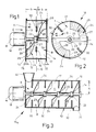
- a container or housing 10 consisting of a cylindrical housing shell 12 and disk-like end walls 14 of a mixer 16 mounted at 15 for mixing sand and binders in the foundry industry is shown in FIG. 1 by a drive shaft driven by a motor 18 and mounted in the end walls 14 20 enforced.
- the shape of the outer edge 27 is adapted to the inner side 11 of the housing shell 12 adjacent to it.
- the end edges 29 of the mixing tools 24 run radially to that drive shaft 20 near the inner surface 13 of the end wall 14.
- built-in bodies 30 - viewed in the direction of the mixer axis M - have a slight extension a from the inside 11 of the housing.
- these built-in bodies 30 are formed by bolt-like parts of length i, which here are somewhat shorter than half the radius q of the housing shell 12.
- the angle of attack between the axis Q of the installation body 30 and the corresponding tangent t of the housing shell 12, designated w in FIG. 2, measures approximately 90 ° there.
- the two mixing tools 24 are provided offset on the drive shaft 20 and convey the batch-working mixer 16, which is not shown in the drawing for reasons of clarity, by means of closure elements in the housing jacket 12, not shown or mixed material supplied or removed in the end walls 14 alternately from a mixing space A of the mixing space 17 to the other side of the plane E into a mixing space B.
- the rotation (arrow x) of the mixing tools 24 is transferred to the mixed material.
- the outer edges 27 of the mixing tools 24 keep the inside of the housing 11 free of caking in an area indicated by b in FIG. 1. This freedom from caking is further favored by the small expansion a of the installation body 30, as a result of which they represent geometrically small obstacles.
- the material to be mixed flows around the built-in body 30 on its way from the one mixing room A or B to the other mixing room B or A and in the process brakes the mixing material rotation; strong shear and friction forces arise, which enable the mixing components to be mixed intensively and quickly.
- the mixing characteristic can be influenced to a large extent.
- the bolt-like installation bodies 30 of circular cross section shown in FIGS. 1, 2, 6 have e.g. proven to be particularly suitable for mixing quartz sand with liquid binders.
- insert bodies 30 with a diameter d of 20 mm and a length i of 100 mm with a housing radius q of 270 mm are shown to be very effective.
- a plurality of mixing tools 24 can be combined axially one behind the other with installation bodies 30 arranged in between to form a continuous mixer 16 a . Due to the different setting of such mixing tools 24 or mixer blades, the mixing movement is superimposed on a transport component from a mixer inlet 32 to a mixture discharge 34. The individual mix components can also be supplied at various points in the housing 10.
- the scraper 36 is formed such that starting from a radial arm 37 of the support sleeve 22 a is an upstanding front end faces 31 of the mounting body 30 of vertical section 38, connecting to the above that level H after a second radial arm 37 a a wandungsnaher second vertical portion 38 a. This is followed by a ridge arm 39 pointing to the mixer axis M, which moves with play below the inside of a housing cover 14 a .
- the vertical section 38 of the scraper 36 entrains mixed material adhering to the end faces 31 of the installation body 30 as it moves.
- the scraper 36 gives the mixed material braked in the area between the installation bodies 30 in the upper mixing space F a new radial movement component; Before the mix can fall back into the lower mixing chamber C, it is distributed radially again.
- an additional horizontal rotation profile 40 protrudes from the supporting sleeve 22 a , the radial extent n of which corresponds approximately to that of the radial arm 37. This rotation keeps the profile 40 located within the path of movement of the mixing tool edge 29 of the inner surface of the housing bottom 14 b of caking free.
- concentric rings 41 connect the installation body 30 to a sieve-like flow body, above which a part 37 a , 38 a of the scraper 36 and under which the mixing tool 24 a rotates.
- the mixed version 16 v of FIG. 6 has proven particularly useful, in which, in addition to the parts already described, a roller 42 is attached to a radial support arm 43 of the support sleeve 22 a .
- the axis K of the roller 42 includes an angle w 1 with the mixer axis M, and the conical circumferential surface 44 of the roller 42 delimits a smaller acute angle w 2 with the housing jacket 12.
- an apron 45 hangs down as a mix carrier to the housing base 14 a .
- the mixer rotor 50 When the mixer rotor 50 consists of the carrying sleeve 22 a , the mixing tool 24 a , the carrying arm 43 and the roller 42, the latter performs an additional self-rotation due to the frictional forces acting on it. This improves the distribution of viscous media on the surface of granular substances.
- the angles shown w1, w2 force an additional spatial shifting of the mix.
- An upper end face 52 of the roller 42 should be at a short distance h from the installation bodies 30; the rotation of that mixing rotor 50, superimposed on the self-rotation of the roller 42, causes the material adhering to the end face 52 to be removed therefrom.
- housing or the container 10 can also be non-cylindrical.
Landscapes
- Chemical & Material Sciences (AREA)
- Chemical Kinetics & Catalysis (AREA)
- Engineering & Computer Science (AREA)
- Mechanical Engineering (AREA)
- Mixers Of The Rotary Stirring Type (AREA)
- Molds, Cores, And Manufacturing Methods Thereof (AREA)
- Mold Materials And Core Materials (AREA)
Applications Claiming Priority (2)
| Application Number | Priority Date | Filing Date | Title |
|---|---|---|---|
| DE4006846A DE4006846A1 (de) | 1990-03-05 | 1990-03-05 | Vorrichtung zum mischen von giessereiformstoffen |
| DE4006846 | 1990-03-05 |
Publications (3)
| Publication Number | Publication Date |
|---|---|
| EP0445436A2 true EP0445436A2 (fr) | 1991-09-11 |
| EP0445436A3 EP0445436A3 (en) | 1992-04-22 |
| EP0445436B1 EP0445436B1 (fr) | 1996-05-22 |
Family
ID=6401439
Family Applications (1)
| Application Number | Title | Priority Date | Filing Date |
|---|---|---|---|
| EP90125711A Expired - Lifetime EP0445436B1 (fr) | 1990-03-05 | 1990-12-28 | Dispositif pour mélanger des matériaux de moulage de fonderie |
Country Status (5)
| Country | Link |
|---|---|
| US (1) | US5393138A (fr) |
| EP (1) | EP0445436B1 (fr) |
| JP (1) | JP2902798B2 (fr) |
| AT (1) | ATE138300T1 (fr) |
| DE (2) | DE4006846A1 (fr) |
Cited By (3)
| Publication number | Priority date | Publication date | Assignee | Title |
|---|---|---|---|---|
| EP0761295A1 (fr) * | 1995-09-12 | 1997-03-12 | List Ag | Mélangeur-pétrisseur |
| EP1745872A2 (fr) * | 2005-06-24 | 2007-01-24 | Klein Anlagenbau AG | Procédé de traitement de mateiaux de moulage de fondérie |
| EP2790823A1 (fr) * | 2011-12-15 | 2014-10-22 | Valmet AB | Unité de mélange destinée à être utilisée dans un mélangeur et mélangeur |
Families Citing this family (11)
| Publication number | Priority date | Publication date | Assignee | Title |
|---|---|---|---|---|
| DE19521130C2 (de) * | 1994-06-16 | 2000-06-15 | Graemer Gerd Volker | Vorrichtung zum Mischen eines körnigen Gutes mit einer Flüssigkeit |
| DE602005024725D1 (de) * | 2005-12-07 | 2010-12-23 | Lico Spa | Vorrichtung und verfahren zum kontinuierlichen horizontalen mischen |
| EP2374528B1 (fr) * | 2009-09-04 | 2014-11-12 | Tsukasa Co., Ltd. | Appareil pour l'agitation de particules de poudre |
| ES2579236T3 (es) * | 2009-10-15 | 2016-08-08 | Bühler AG | Método y uso para refinar |
| ES2581392T5 (es) * | 2009-10-15 | 2022-05-13 | Buehler Ag | Procedimiento y uso para la trituración |
| FI126111B (fi) * | 2012-05-07 | 2016-06-30 | Maricap Oy | Menetelmä ja laitteisto materiaalin syöttämiseksi rotaatiomuokkainlaitteeseen |
| DE102013219061B3 (de) * | 2013-09-23 | 2014-10-02 | Klein Anlagenbau Ag | Mischwerkzeug |
| JP5718511B1 (ja) * | 2014-06-17 | 2015-05-13 | 株式会社清田鋳機 | 鋳物砂用連続ミキサーの清掃方法 |
| CN105413512A (zh) * | 2015-11-30 | 2016-03-23 | 天津威晟番茄制品有限公司 | 一种番茄酱包装机的搅拌装置 |
| CN106424546A (zh) * | 2016-11-09 | 2017-02-22 | 郑州莉迪亚医药科技有限公司 | 一种覆膜砂加工装置 |
| CN114210249A (zh) * | 2021-12-30 | 2022-03-22 | 沈阳智尔镁科技有限公司 | 一种镁砂自动化加工生产线及其系统 |
Citations (8)
| Publication number | Priority date | Publication date | Assignee | Title |
|---|---|---|---|---|
| US1645990A (en) * | 1922-11-21 | 1927-10-18 | Baker Perkins Co Inc | Vessel for mixing chocolate and similar substances |
| US2413603A (en) * | 1944-05-10 | 1946-12-31 | Herbert S Simpson | Mixer |
| FR2011198A1 (en) * | 1968-06-19 | 1970-02-27 | Badische Maschf Gmbh | Foundry sand mixture |
| DE3613612A1 (de) * | 1985-04-30 | 1986-11-06 | Gumix S.A., Barcelona | Turbomisch-strangpresse |
| DE3639432A1 (de) * | 1985-12-31 | 1987-07-02 | Keramikmaschinen Goerlitz Veb | Vorrichtung zum andruecken und ausheben von kollerlaeufern in mischern |
| EP0279255A1 (fr) * | 1987-02-03 | 1988-08-24 | CARLE & MONTANARI S.p.A. | Appareil pour diminuer la viscosité dans des suspensions de solides dans des porteurs de graisse tel que des masses de chocolat |
| EP0303728A1 (fr) * | 1987-08-21 | 1989-02-22 | Schumacher, Walter Dr. Ing. | Dispositif pour extruder, expanser et/ou traiter thermiquement des matières ou des mélanges de matières |
| DE3914694A1 (de) * | 1988-07-04 | 1990-01-11 | Sanyo Chemical Ind Ltd | Ruehrvorrichtung |
Family Cites Families (17)
| Publication number | Priority date | Publication date | Assignee | Title |
|---|---|---|---|---|
| FR625884A (fr) * | 1927-08-22 | |||
| NL71608C (fr) * | ||||
| US1546335A (en) * | 1922-05-09 | 1925-07-14 | Barber Asphalt Co | Mixing machinery |
| US2029690A (en) * | 1933-07-10 | 1936-02-04 | Standard Oil Co | Process and apparatus for contacting two liquids |
| US2082796A (en) * | 1934-12-21 | 1937-06-08 | Gaertner Moritz | Agitator |
| US2227522A (en) * | 1939-08-19 | 1941-01-07 | Anderson Co V D | Combined agitator and conveyer mechanism |
| US2626786A (en) * | 1947-05-05 | 1953-01-27 | Leonard D Mcglothlin | Automatic consistency control means |
| GB635376A (en) * | 1947-08-14 | 1950-04-05 | Donald Gwilliam Price | Improvements in and relating to the mixing or blending of powdered or granular substances |
| DE1075561B (de) * | 1953-09-15 | 1960-02-18 | zugl | Misch- und Knetmaschine |
| DE1173787B (de) * | 1958-09-16 | 1964-07-09 | Ferdinand Wultsch Dipl Ing Dr | Vorrichtung zum Zerlegen von Zellstoffaserbuendeln in Einzelfasern |
| FR2302774A1 (fr) * | 1975-03-03 | 1976-10-01 | Sapic | Procede et installation de preparation d'un melange pour moules de fonderie ou analogues, avec formation d'un premelange |
| US3980013A (en) * | 1975-09-15 | 1976-09-14 | The French Oil Mill Machinery Company | Split worm for screw press |
| CH602172A5 (fr) * | 1975-10-10 | 1978-07-31 | Fischer Ag Georg | |
| US4194925A (en) * | 1977-08-15 | 1980-03-25 | Columbia Machine, Inc. | Method and apparatus for washing mixing containers |
| US4155657A (en) * | 1978-03-10 | 1979-05-22 | Chemed Corporation | Continuous mixer for preparing emulsions |
| DE8234900U1 (de) * | 1981-12-18 | 1983-03-24 | Lüber, Werner, Bazenheid | Rotationsmischvorrichtung fuer granulare gueter, insbesondere kernsand |
| DE3818453A1 (de) * | 1988-05-31 | 1989-12-07 | Janke & Kunkel Kg | Dispergiermaschine |
-
1990
- 1990-03-05 DE DE4006846A patent/DE4006846A1/de active Granted
- 1990-12-28 AT AT90125711T patent/ATE138300T1/de not_active IP Right Cessation
- 1990-12-28 EP EP90125711A patent/EP0445436B1/fr not_active Expired - Lifetime
- 1990-12-28 DE DE59010341T patent/DE59010341D1/de not_active Expired - Lifetime
-
1991
- 1991-02-18 JP JP3045805A patent/JP2902798B2/ja not_active Expired - Fee Related
-
1993
- 1993-02-09 US US08/015,453 patent/US5393138A/en not_active Expired - Lifetime
Patent Citations (8)
| Publication number | Priority date | Publication date | Assignee | Title |
|---|---|---|---|---|
| US1645990A (en) * | 1922-11-21 | 1927-10-18 | Baker Perkins Co Inc | Vessel for mixing chocolate and similar substances |
| US2413603A (en) * | 1944-05-10 | 1946-12-31 | Herbert S Simpson | Mixer |
| FR2011198A1 (en) * | 1968-06-19 | 1970-02-27 | Badische Maschf Gmbh | Foundry sand mixture |
| DE3613612A1 (de) * | 1985-04-30 | 1986-11-06 | Gumix S.A., Barcelona | Turbomisch-strangpresse |
| DE3639432A1 (de) * | 1985-12-31 | 1987-07-02 | Keramikmaschinen Goerlitz Veb | Vorrichtung zum andruecken und ausheben von kollerlaeufern in mischern |
| EP0279255A1 (fr) * | 1987-02-03 | 1988-08-24 | CARLE & MONTANARI S.p.A. | Appareil pour diminuer la viscosité dans des suspensions de solides dans des porteurs de graisse tel que des masses de chocolat |
| EP0303728A1 (fr) * | 1987-08-21 | 1989-02-22 | Schumacher, Walter Dr. Ing. | Dispositif pour extruder, expanser et/ou traiter thermiquement des matières ou des mélanges de matières |
| DE3914694A1 (de) * | 1988-07-04 | 1990-01-11 | Sanyo Chemical Ind Ltd | Ruehrvorrichtung |
Cited By (5)
| Publication number | Priority date | Publication date | Assignee | Title |
|---|---|---|---|---|
| EP0761295A1 (fr) * | 1995-09-12 | 1997-03-12 | List Ag | Mélangeur-pétrisseur |
| EP1745872A2 (fr) * | 2005-06-24 | 2007-01-24 | Klein Anlagenbau AG | Procédé de traitement de mateiaux de moulage de fondérie |
| EP1745872A3 (fr) * | 2005-06-24 | 2009-03-11 | Klein Anlagenbau AG | Procédé de traitement de mateiaux de moulage de fondérie |
| EP2790823A1 (fr) * | 2011-12-15 | 2014-10-22 | Valmet AB | Unité de mélange destinée à être utilisée dans un mélangeur et mélangeur |
| EP2790823A4 (fr) * | 2011-12-15 | 2015-07-08 | Valmet Oy | Unité de mélange destinée à être utilisée dans un mélangeur et mélangeur |
Also Published As
| Publication number | Publication date |
|---|---|
| JPH04224042A (ja) | 1992-08-13 |
| ATE138300T1 (de) | 1996-06-15 |
| JP2902798B2 (ja) | 1999-06-07 |
| EP0445436A3 (en) | 1992-04-22 |
| DE59010341D1 (de) | 1996-06-27 |
| US5393138A (en) | 1995-02-28 |
| DE4006846C2 (fr) | 1992-10-22 |
| EP0445436B1 (fr) | 1996-05-22 |
| DE4006846A1 (de) | 1991-09-12 |
Similar Documents
| Publication | Publication Date | Title |
|---|---|---|
| DE3883669T2 (de) | Vorrichtung, insbesondere zum gleichmässigen Verteilen fester Teilchen oder/und Flüssigkeiten, und Apparat mit einer solchen Vorrichtung. | |
| EP0445436B1 (fr) | Dispositif pour mélanger des matériaux de moulage de fonderie | |
| DE1075561B (de) | Misch- und Knetmaschine | |
| CH682788A5 (de) | Maschine zum Bearbeiten von Schokolademassen. | |
| DE10110910C1 (de) | Mischer zum Herstellen pastöser Produkte wie Salben, Cremes und Emulsionen | |
| DE3635877C1 (de) | Mischtrockner | |
| DE1204632B (de) | Tellermischer | |
| DE1211904B (de) | Ruehrwerksmuehle | |
| EP0211230B1 (fr) | Dispositif pour mélanger des matériaux solides et des liquides | |
| DE1245690B (de) | Mahlvorrichtung | |
| DE3921899A1 (de) | Einwellenmischmaschine fuer trockene und feuchte stoffe | |
| DE2146611A1 (de) | Kuehlmischer | |
| CH444739A (de) | Vorrichtung zum Mischen von Flüssigkeiten von pulverigen bis körnigen Materialien | |
| DE3105558A1 (de) | Zerhackervorrichtung fuer einen konus-schnecken-mischer | |
| DE1941831A1 (de) | Mischmaschine | |
| DE19521130C2 (de) | Vorrichtung zum Mischen eines körnigen Gutes mit einer Flüssigkeit | |
| DE3641413C1 (en) | Apparatus for processing materials | |
| DE581625C (de) | Mischzentrifuge | |
| DE9206589U1 (de) | Vakuummassiermenger | |
| AT218943B (de) | Mischer mit einer um eine senkrechte Achse umlaufenden Mischschüssel | |
| DE1557223B2 (de) | Vorrichtung zum Dispergieren von Gasen und/oder Fluessigkeiten und/oder Feststoffen in Fluessigkeiten | |
| DE2739106C2 (de) | Vorrichtung zum Rühren einer feste Teilchen enthaltenden Flüssigkeit | |
| DE1194375B (de) | Tellermischer | |
| DE1141517B (de) | Vorrichtung zum Zerkleinern, Mischen und Homogenisieren von Stoffen sowie zur Durchfuehrung mechano-chemischer Reaktionen | |
| DE1557223C (de) | Vorrichtung zum Dispergieren von Ga sen und/oder Flüssigkeiten und/oder Fest Stoffen in Flüssigkeiten Ausscheidung aus 1295524 |
Legal Events
| Date | Code | Title | Description |
|---|---|---|---|
| PUAI | Public reference made under article 153(3) epc to a published international application that has entered the european phase |
Free format text: ORIGINAL CODE: 0009012 |
|
| AK | Designated contracting states |
Kind code of ref document: A2 Designated state(s): AT BE CH DE DK ES FR GB GR IT LI LU NL SE |
|
| PUAL | Search report despatched |
Free format text: ORIGINAL CODE: 0009013 |
|
| AK | Designated contracting states |
Kind code of ref document: A3 Designated state(s): AT BE CH DE DK ES FR GB GR IT LI LU NL SE |
|
| 17P | Request for examination filed |
Effective date: 19920610 |
|
| RBV | Designated contracting states (corrected) |
Designated state(s): AT CH DE FR GB IT LI NL |
|
| 17Q | First examination report despatched |
Effective date: 19930709 |
|
| GRAH | Despatch of communication of intention to grant a patent |
Free format text: ORIGINAL CODE: EPIDOS IGRA |
|
| GRAH | Despatch of communication of intention to grant a patent |
Free format text: ORIGINAL CODE: EPIDOS IGRA |
|
| GRAH | Despatch of communication of intention to grant a patent |
Free format text: ORIGINAL CODE: EPIDOS IGRA |
|
| GRAA | (expected) grant |
Free format text: ORIGINAL CODE: 0009210 |
|
| AK | Designated contracting states |
Kind code of ref document: B1 Designated state(s): AT CH DE FR GB IT LI NL |
|
| PG25 | Lapsed in a contracting state [announced via postgrant information from national office to epo] |
Ref country code: IT Free format text: LAPSE BECAUSE OF FAILURE TO SUBMIT A TRANSLATION OF THE DESCRIPTION OR TO PAY THE FEE WITHIN THE PRESCRIBED TIME-LIMIT;WARNING: LAPSES OF ITALIAN PATENTS WITH EFFECTIVE DATE BEFORE 2007 MAY HAVE OCCURRED AT ANY TIME BEFORE 2007. THE CORRECT EFFECTIVE DATE MAY BE DIFFERENT FROM THE ONE RECORDED. Effective date: 19960522 |
|
| REF | Corresponds to: |
Ref document number: 138300 Country of ref document: AT Date of ref document: 19960615 Kind code of ref document: T |
|
| REF | Corresponds to: |
Ref document number: 59010341 Country of ref document: DE Date of ref document: 19960627 |
|
| GBT | Gb: translation of ep patent filed (gb section 77(6)(a)/1977) |
Effective date: 19960806 |
|
| ET | Fr: translation filed | ||
| PG25 | Lapsed in a contracting state [announced via postgrant information from national office to epo] |
Ref country code: AT Effective date: 19961228 |
|
| PG25 | Lapsed in a contracting state [announced via postgrant information from national office to epo] |
Ref country code: LI Effective date: 19961231 Ref country code: CH Effective date: 19961231 |
|
| PLBE | No opposition filed within time limit |
Free format text: ORIGINAL CODE: 0009261 |
|
| STAA | Information on the status of an ep patent application or granted ep patent |
Free format text: STATUS: NO OPPOSITION FILED WITHIN TIME LIMIT |
|
| 26N | No opposition filed | ||
| REG | Reference to a national code |
Ref country code: CH Ref legal event code: PL |
|
| PGFP | Annual fee paid to national office [announced via postgrant information from national office to epo] |
Ref country code: NL Payment date: 20001221 Year of fee payment: 11 |
|
| REG | Reference to a national code |
Ref country code: FR Ref legal event code: TP |
|
| REG | Reference to a national code |
Ref country code: GB Ref legal event code: IF02 |
|
| PG25 | Lapsed in a contracting state [announced via postgrant information from national office to epo] |
Ref country code: NL Free format text: LAPSE BECAUSE OF NON-PAYMENT OF DUE FEES Effective date: 20020701 |
|
| NLV4 | Nl: lapsed or anulled due to non-payment of the annual fee |
Effective date: 20020701 |
|
| PGFP | Annual fee paid to national office [announced via postgrant information from national office to epo] |
Ref country code: GB Payment date: 20051122 Year of fee payment: 16 |
|
| PGFP | Annual fee paid to national office [announced via postgrant information from national office to epo] |
Ref country code: FR Payment date: 20051216 Year of fee payment: 16 |
|
| GBPC | Gb: european patent ceased through non-payment of renewal fee |
Effective date: 20061228 |
|
| REG | Reference to a national code |
Ref country code: FR Ref legal event code: ST Effective date: 20070831 |
|
| PG25 | Lapsed in a contracting state [announced via postgrant information from national office to epo] |
Ref country code: GB Free format text: LAPSE BECAUSE OF NON-PAYMENT OF DUE FEES Effective date: 20061228 |
|
| PG25 | Lapsed in a contracting state [announced via postgrant information from national office to epo] |
Ref country code: FR Free format text: LAPSE BECAUSE OF NON-PAYMENT OF DUE FEES Effective date: 20070102 |
|
| PGFP | Annual fee paid to national office [announced via postgrant information from national office to epo] |
Ref country code: DE Payment date: 20100222 Year of fee payment: 20 |
|
| PG25 | Lapsed in a contracting state [announced via postgrant information from national office to epo] |
Ref country code: DE Free format text: LAPSE BECAUSE OF EXPIRATION OF PROTECTION Effective date: 20101228 |