EP0445436A2 - Apparatus for mixing foundry moulding materials - Google Patents
Apparatus for mixing foundry moulding materials Download PDFInfo
- Publication number
- EP0445436A2 EP0445436A2 EP90125711A EP90125711A EP0445436A2 EP 0445436 A2 EP0445436 A2 EP 0445436A2 EP 90125711 A EP90125711 A EP 90125711A EP 90125711 A EP90125711 A EP 90125711A EP 0445436 A2 EP0445436 A2 EP 0445436A2
- Authority
- EP
- European Patent Office
- Prior art keywords
- mixing
- drive shaft
- container
- mixing tool
- roller
- Prior art date
- Legal status (The legal status is an assumption and is not a legal conclusion. Google has not performed a legal analysis and makes no representation as to the accuracy of the status listed.)
- Granted
Links
Images
Classifications
-
- B—PERFORMING OPERATIONS; TRANSPORTING
- B01—PHYSICAL OR CHEMICAL PROCESSES OR APPARATUS IN GENERAL
- B01F—MIXING, e.g. DISSOLVING, EMULSIFYING OR DISPERSING
- B01F27/00—Mixers with rotary stirring devices in fixed receptacles; Kneaders
- B01F27/60—Mixers with rotary stirring devices in fixed receptacles; Kneaders with stirrers rotating about a horizontal or inclined axis
- B01F27/70—Mixers with rotary stirring devices in fixed receptacles; Kneaders with stirrers rotating about a horizontal or inclined axis with paddles, blades or arms
- B01F27/707—Mixers with rotary stirring devices in fixed receptacles; Kneaders with stirrers rotating about a horizontal or inclined axis with paddles, blades or arms the paddles co-operating, e.g. intermeshing, with elements on the receptacle wall
-
- B—PERFORMING OPERATIONS; TRANSPORTING
- B01—PHYSICAL OR CHEMICAL PROCESSES OR APPARATUS IN GENERAL
- B01F—MIXING, e.g. DISSOLVING, EMULSIFYING OR DISPERSING
- B01F27/00—Mixers with rotary stirring devices in fixed receptacles; Kneaders
- B01F27/80—Mixers with rotary stirring devices in fixed receptacles; Kneaders with stirrers rotating about a substantially vertical axis
- B01F27/86—Mixers with rotary stirring devices in fixed receptacles; Kneaders with stirrers rotating about a substantially vertical axis co-operating with deflectors or baffles fixed to the receptacle
-
- B—PERFORMING OPERATIONS; TRANSPORTING
- B01—PHYSICAL OR CHEMICAL PROCESSES OR APPARATUS IN GENERAL
- B01F—MIXING, e.g. DISSOLVING, EMULSIFYING OR DISPERSING
- B01F27/00—Mixers with rotary stirring devices in fixed receptacles; Kneaders
- B01F27/80—Mixers with rotary stirring devices in fixed receptacles; Kneaders with stirrers rotating about a substantially vertical axis
- B01F27/95—Mixers with rotary stirring devices in fixed receptacles; Kneaders with stirrers rotating about a substantially vertical axis with stirrers having planetary motion, i.e. rotating about their own axis and about a sun axis
- B01F27/951—Mixers with rotary stirring devices in fixed receptacles; Kneaders with stirrers rotating about a substantially vertical axis with stirrers having planetary motion, i.e. rotating about their own axis and about a sun axis with at least one stirrer mounted on the sun axis
-
- B—PERFORMING OPERATIONS; TRANSPORTING
- B22—CASTING; POWDER METALLURGY
- B22C—FOUNDRY MOULDING
- B22C5/00—Machines or devices specially designed for dressing or handling the mould material so far as specially adapted for that purpose
- B22C5/04—Machines or devices specially designed for dressing or handling the mould material so far as specially adapted for that purpose by grinding, blending, mixing, kneading, or stirring
- B22C5/0409—Blending, mixing, kneading or stirring; Methods therefor
-
- B—PERFORMING OPERATIONS; TRANSPORTING
- B01—PHYSICAL OR CHEMICAL PROCESSES OR APPARATUS IN GENERAL
- B01F—MIXING, e.g. DISSOLVING, EMULSIFYING OR DISPERSING
- B01F27/00—Mixers with rotary stirring devices in fixed receptacles; Kneaders
- B01F27/23—Mixers with rotary stirring devices in fixed receptacles; Kneaders characterised by the orientation or disposition of the rotor axis
- B01F27/232—Mixers with rotary stirring devices in fixed receptacles; Kneaders characterised by the orientation or disposition of the rotor axis with two or more rotation axes
- B01F27/2321—Mixers with rotary stirring devices in fixed receptacles; Kneaders characterised by the orientation or disposition of the rotor axis with two or more rotation axes having different inclinations, e.g. non parallel
-
- B—PERFORMING OPERATIONS; TRANSPORTING
- B01—PHYSICAL OR CHEMICAL PROCESSES OR APPARATUS IN GENERAL
- B01F—MIXING, e.g. DISSOLVING, EMULSIFYING OR DISPERSING
- B01F27/00—Mixers with rotary stirring devices in fixed receptacles; Kneaders
- B01F27/23—Mixers with rotary stirring devices in fixed receptacles; Kneaders characterised by the orientation or disposition of the rotor axis
- B01F27/232—Mixers with rotary stirring devices in fixed receptacles; Kneaders characterised by the orientation or disposition of the rotor axis with two or more rotation axes
- B01F27/2324—Mixers with rotary stirring devices in fixed receptacles; Kneaders characterised by the orientation or disposition of the rotor axis with two or more rotation axes planetary
-
- B—PERFORMING OPERATIONS; TRANSPORTING
- B01—PHYSICAL OR CHEMICAL PROCESSES OR APPARATUS IN GENERAL
- B01F—MIXING, e.g. DISSOLVING, EMULSIFYING OR DISPERSING
- B01F27/00—Mixers with rotary stirring devices in fixed receptacles; Kneaders
- B01F27/60—Mixers with rotary stirring devices in fixed receptacles; Kneaders with stirrers rotating about a horizontal or inclined axis
-
- B—PERFORMING OPERATIONS; TRANSPORTING
- B01—PHYSICAL OR CHEMICAL PROCESSES OR APPARATUS IN GENERAL
- B01F—MIXING, e.g. DISSOLVING, EMULSIFYING OR DISPERSING
- B01F27/00—Mixers with rotary stirring devices in fixed receptacles; Kneaders
- B01F27/80—Mixers with rotary stirring devices in fixed receptacles; Kneaders with stirrers rotating about a substantially vertical axis
-
- B—PERFORMING OPERATIONS; TRANSPORTING
- B01—PHYSICAL OR CHEMICAL PROCESSES OR APPARATUS IN GENERAL
- B01F—MIXING, e.g. DISSOLVING, EMULSIFYING OR DISPERSING
- B01F33/00—Other mixers; Mixing plants; Combinations of mixers
- B01F33/80—Mixing plants; Combinations of mixers
- B01F33/82—Combinations of dissimilar mixers
Abstract
Description
Die Erfindung betrifft eine Vorrichtung zum Mischen von Gießereiformstoffen, insbesondere von Sand und Bindemittel, mit von einer Antriebswelle abragendem und mit ihr in einem Bahälter drehbarem Mischwerkzeug.The invention relates to a device for mixing foundry molding materials, in particular sand and binder, with a mixing tool protruding from a drive shaft and rotatable with it in a container.
Derartige Mischer mit rotierendem Mischwerkzeug sind in der Gießereiindustrie zum Vermischen von Sand und Bindemitteln üblich. Ihre Mischwirkung wird dadurch erreicht, daß die flügelartig gestalteten Mischwerkzeuge zum Mischgut mit einer Relativgeschwindigkeit umlaufen, dieses reiben, zerteilen und umschichten. Das Mischgut wird von der Wand des Mischbehälters gebremst und im Zentrum vom Mischwerkzeug bewegt.Such mixers with a rotating mixing tool are common in the foundry industry for mixing sand and binders. Their mixing effect is achieved in that the wing-shaped mixing tools rotate with the material to be mixed at a relative speed, rub, divide and rearrange it. The mix is braked by the wall of the mixing container and moved in the center by the mixing tool.
Mischwerkzeuge können gemäß DE-PS 26 08 775 in gestreckten Durchlaufmischern mit horizontaler Antriebswelle, nach DE-GM 82 34 900 in chargenweise zu füllenden Rotationsmischern mit vertikaler Antriebswelle oder aber auch mit schräg angeordneter Achse arbeiten.Mixing tools can work according to DE-PS 26 08 775 in straight flow mixers with a horizontal drive shaft, according to DE-GM 82 34 900 in batch mixers to be filled with a vertical drive shaft or with an inclined axis.
Die Mischwirkung von Mischern mit rotierendem Mischwerkzeug läßt sich durch Erhöhung der Mischwerkzeugdrehzahl solange steigern, bis die Reibung des Mischgutes an der Mischbehälterwand nicht mehr ausreicht und das Mischgut als mehr oder minder kompakte Masse der Drehbewegung des Mischwerkzeuges folgt. Damit sind die für den Mischvorgang erforderlichen Reib-, Zerteil- und Umshichtkräfte begrenzt. Diese Eigenschaft macht sich besonders dann nachteilig bemerkbar, wenn auch viskose Komponenten im Mischgut vorhanden sind.The mixing effect of mixers with a rotating mixing tool can be increased by increasing the speed of the mixing tool until the friction of the material to be mixed on the wall of the mixing container is no longer sufficient and the material as a more or less compact mass follows the rotary movement of the mixing tool. This limits the friction, cutting and conversion forces required for the mixing process. This property is particularly noticeable when viscous components are present in the mix.
Soll bei Mischern mit vertikaler Achse die Umfangsgeschwindigkeit gesteigert werden, kommen oberhalb der Mischwerkzeuge Profile zum Einsatz, deren Längsachsen sich parallel zur Mischbehälterwand erstrecken, an der sie festgelegt sind. Diese Profile bremsen das Mischgut. In diesem Bereich kann aber die Mischbehälterwand nicht von einem umlaufenden Schaber von Anbackungen freigehalten werden. Die angebackenen Stoffe fehlen zum einen in der Mischung und erfordern zum anderen unter Umständen einen beträchtlichen Reinigungsaufwand.If the peripheral speed is to be increased for mixers with a vertical axis, profiles are used above the mixing tools, the longitudinal axes of which extend parallel to the mixing container wall on which they are fixed. These profiles slow down the mix. In this area, however, the wall of the mixing container cannot be kept free from caking by a rotating scraper. On the one hand, the baked-on substances are missing in the mixture and, on the other hand, may require considerable cleaning effort.
Angesichts dieser Gegebenheiten hat sich der Erfinder das Ziel gesetzt, eine Vorrichtung der gattungsgemäßen Art mit rotierendem Mischwerkzeug zu schaffen, die zum einen eine hohe Mischintensität anbietet sowie zum anderen durch die Mischwerkzeuge und die Bewegung des Mischgutes weitgehend frei von Anbackungen gehalten wird.In view of these circumstances, the inventor has set himself the goal of creating a device of the generic type with a rotating mixing tool which, on the one hand, offers a high mixing intensity and, on the other hand, is kept largely free of caking by the mixing tools and the movement of the material to be mixed.
Zur Lösung der vom Erfinder gesehenen Aufgabe führt, daß in wellenparallelem Abstand vom freien Ende des drehbaren Mischwerkzeuges von der Wandung des Behälters zumindest ein Einbaukörper mit geringer seitlicher Erstreckung in das Mischgut ragt. Dazu hat es sich als günstig erwiesen, den Einbaukörper messerartig oder als Bolzen geringen Querschnitts auszubilden oder als Stab mit tropfenförmigem Querschnitt.To achieve the object seen by the inventor, at least one installation body with a slight lateral extension projects into the mix at a distance parallel to the shaft from the free end of the rotatable mixing tool from the wall of the container. For this purpose, it has proven to be advantageous to design the installation body in the manner of a knife or as a bolt with a small cross-section or as a rod with a drop-shaped cross-section.
Durch die geringe seitliche Ausdehnung der Einbaukörper hält die Strömung des Mischgutes die Behälterwand im Bereich zwischen den Einbaukörpern anbackungsfrei. Die spezifische Auswahl von Anzahl, Querschnitt und Länge der Einbaukörper sowie ihres Anstellwinkels zur Mischerwandung erlaubt die Bestimmung der Mischcharakteristik in weitem Umfang.Due to the small lateral expansion of the installation bodies, the flow of the mixed material keeps the container wall in the area between the installation bodies free of caking. The specific selection of the number, cross-section and length of the installation bodies and their angle of attack to the mixer wall allows the mixing characteristics to be determined to a large extent.
Erfindungsgemäß schlanke, messerartige oder mit tropfenförmigem Querschnitt ausgeführte Einbaukörper bewirken eine Aufteilung des Mischgutstromes mit wenig Reibung. Sie ermöglichen beispielsweise die schnelle Vermischung von trockenen, temperaturempfindlichen Stoffen. Fülligere Querschnitte ergeben einen größeren Reibungseinfluß und sind etwa zum Vermischen fester und flüssiger Komponenten miteinander besser geeignet - etwa Einbaukörper mit kreisförmigem Querschnitt zum Behandeln von Quarzsand mit flüssigem Bindemittel.According to the invention, slim, knife-like or drop-shaped cross-sectional bodies result in a distribution of the mix flow with little friction. For example, they enable the quick mixing of dry, temperature-sensitive substances. Fatter cross-sections result in a greater influence of friction and are more suitable, for example, for mixing solid and liquid components with one another - for example built-in bodies with a circular cross-section for treating quartz sand with liquid binder.
Zur Beeinflussung der Mischgutströme kann die Achse des Einbaukörpers auch gekrümmt ausgeführt werden; mit einer Verwindung der Einbaukörper ergeben sich zusätzliche räumliche Strömungen im Mischgut, die etwa beim Mischen flüssiger Komponenten hilfreich sein können.In order to influence the mix flows, the axis of the installation body can also be curved; twisting the installation bodies results in additional spatial flows in the mix, which can be helpful, for example, when mixing liquid components.
Ebenfalls ist es im Rahmen der Erfindung möglich, die Einbaukörper durch sie kreuzende Ringe oder Spiralen zu einem siebartigen Strömngskörper zu verbinden; da die Teile eines solchen Siebes sich gegenseitig stabilisieren, vermögen sie mit einer besonders geringen Dicke ausgeführt zu werden, ohne daß sie dem Mischgutstromdruck ausweichen.It is also possible within the scope of the invention to connect the built-in bodies by means of rings or spirals crossing them to form a sieve-like flow body; since the parts of such a screen stabilize each other, they can be made with a particularly small thickness without evading the mix stream pressure.
Nach einem weiteren Merkmal der Erfindung bestimmen die Einbaukörper eine gemeinsame Ebene, welche das Behälterinnere in Mischräume unterteilt. Bevorzugtermaßen ist der Einbaukörper zwischen zumindest zwei von der Antriebswelle benachbart abragenden Mischwerkzeugen vorgesehen, deren jedes in einem der Mischräume umläuft und das Mischgut wechselweise von einem der Mischräume in den anderen Mischraum befördert. Dabei überträgt sich die Rotation der Mischwerkzeuge auf das Mischgut. Durch jene Einbaukörper entstehen starke Scheer- und Reibungskräfte, die eine intensive schnelle Vermischung der Mischkomponenten ermöglichen.According to a further feature of the invention, the installation bodies determine a common level which divides the interior of the container into mixing rooms. The installation body is preferably provided between at least two mixing tools projecting adjacent to the drive shaft, each of which rotates in one of the mixing rooms and alternately conveys the mixed material from one of the mixing rooms to the other mixing room. The rotation of the mixing tools is transferred to the mix. These built-in bodies create strong shear and friction forces, which enable the mixing components to be mixed intensively and quickly.
Bei einer Ausführungsform der erfindungsgemäßen Vorrichtung ragen zumindest zwei Mischwerkzeuge versetzt von einem gemeinsamen Tragring od.dgl. Tragelement der Antriebswelle ab, wobei zwischen ihnen jene Ebene für die Einbaukörper etwa vertikal verläuft. Auch können mehrere solche Mischwerkzeugeinheiten axial hintereinander mit dazwischen angeordneten Einbau- oder Strömungskörpern zu einem Durchlaufmischer kombiniert werden. Durch unterschiedliche Anstellung der Mischwerkzeugschaufeln wird der Mischbewegung eine Transportkomponente vom Mischguteinlaß zum Mischgutabwurf überlagert.In one embodiment of the device according to the invention, at least two mixing tools or the like protrude offset from a common support ring. Support element of the drive shaft, between which that plane for the installation body runs approximately vertically. Several such mixing tool units can also be combined axially one behind the other with built-in or flow bodies arranged in between to form a continuous mixer. By moving the mixing tool blades differently, a transport component from the mixture inlet to the mixture discharge is superimposed on the mixing movement.
Auch liegt es im Rahmen der Erfindung, in jedem der Mischräume --statt einer -- mehrere Mischwerkzeugschaufeln an der Mischerachse vorzusehen.It is also within the scope of the invention to provide several mixing tool blades on the mixer axis in each of the mixing spaces instead of one.
Eine weitere Ausführung weist die Einbaukörper im Behälter oberhalb des Mischwerkzeuges auf, die eine -- zwei übereinander liegende Mischräume trennende -- horizontale oder zur Horizontalen geneigte Ebene bestimmen. Unterhalb dieser Ebene ist das von der Antriebswelle abragende Mischwerkzeug mit einer über diese Ebene greifenden Abstreifeinrichtung verbunden. Da bei einer Ausführung mit senkrechter oder geneigter Achse die Schwerkraft das Mischgut nach unten bewegt, ist es ausreichend, nur im unteren Mischraum ein angestelltes Mischwerkzeug anzuordnen; der Rücktransport wird von der Schwerkraft bewirkt. Auch genügt es hier, den oberen Mischraum mittels einer leichten Abstreifeinrichtung anbackungsfrei zu halten.A further embodiment has the built-in body in the container above the mixing tool, which determine a horizontal plane or a plane that is inclined to the horizontal, separating two mixing chambers lying one above the other. Below this level, the mixing tool projecting from the drive shaft is connected to a stripping device which extends over this level. Since, in the case of a version with a vertical or inclined axis, gravity moves the mix downward, it is sufficient to arrange a mixing tool only in the lower mixing chamber; the return transport is effected by gravity. It is also sufficient here to keep the upper mixing area free of caking by means of a light stripping device.
Als günstig hat sich eine Abstreifeinrichtung mit einem radial von der Antriebswelle abstehenden stabartigen Abschnitt, einen dazu geneigten und vor die Stirnflächen der Einbaukörper reichenden zweiten Abschnitt sowie einen an der Behälterinnenseite verlaufenden weiteren Abschnitt erwiesen.A scraper device with a rod-like section protruding radially from the drive shaft, a second section inclined to it and reaching in front of the end faces of the installation bodies, and a further section running on the inside of the container have proven to be favorable.
Zudem kann bevorzugt noch ein am Deckel des geschlossenen Behälters führbarer Abschnitt vorgesehen werden; dank dessen wird die Deckelinnenseite anbackungsfrei gehalten, und der zweite Abschnitt der Abstreifeinrichtung bewirkt, daß im oberen Mischraum auch auf sowie an den Stirnflächen der Einbaukörper haftendes Mischgut abgestreift sowie dem im Bereich zwischen den Einbaukörpern abgebremsten Mischgut eine neue radiale Bewegungskomponente erteilt wird. Bevor das Mischgut zurück in den unteren Mischraum fallen kann, wird es nochmals radial verteilt.In addition, a section that can be guided on the lid of the closed container can preferably be provided; thanks to this, the inside of the lid is kept free of caking, and the second section of the stripping device ensures that in the upper mixing space also on the end faces of the built-in mixing material is scraped off and the mixed material decelerated in the area between the built-in bodies is given a new radial movement component. Before the mix can fall back into the lower mixing room, it is distributed radially again.
Eine erfindungsgemäße Vorrichtung zur Verteilung viskoser Medien auf der Oberfläche körniger Stoffe enthält unterhalb der von den Einbaukörpern bestimmten Ebene ein von der Antriebswelle abragendes Mischwerkzeug sowie zumindest eine relativ zur Antriebswelle rotierende Rolle, deren Umfangsfläche mit der Behälterinnenfläche vorteilhafterweise einen spitzen Winkel begrenzt. Die Achse dieser Rolle soll mit der Antriebswelle einen Winkel einschließen, der kleiner als 90° ist.A device according to the invention for distributing viscous media on the surface of granular substances contains, below the plane determined by the installation bodies, a mixing tool protruding from the drive shaft and at least one roller rotating relative to the drive shaft, the peripheral surface of which advantageously delimits an acute angle with the inner surface of the container. The axis of this roller should form an angle with the drive shaft that is less than 90 °.
Bei der Rotation des gesamten Mischläufers führt die Rolle durch die auf sie wirkenden Reibungskräfte eine zusätzliche Eigenrotation aus, wodurch die erwähnte Verteilung viskoser Medien auf der Oberfläche körniger Stoffe verbessert wird. Durch die Winkelstellung wird eine zusätzliche räumliche Umschichtung des Mischgutes erzwungen.When the entire mixer rotor rotates, the roller performs an additional self-rotation due to the frictional forces acting on it, which improves the aforementioned distribution of viscous media on the surface of granular substances. The angular position forces an additional spatial shifting of the mix.
Als günstig hat es sich erwiesen, die Rolle bzw. ihre Umfangsfläche sich zur Ebene der Einbaukörper hin konisch verjüngen zu lassen und/oder die obere Stirnfläche der Rolle in geringem Abstand zu den zugeordneten Einbaukörpern vorzusehen, um so ein Abstreifen von Mischgut zu begünstigen.It has proven to be advantageous to have the roller or its circumferential surface taper conically towards the level of the installation bodies and / or to provide the upper end face of the roller at a short distance from the assigned installation bodies, so as to encourage stripping of the mixed material.
Daß die Umfangsfläche der Rolle mit Aus- und/oder Einformungen versehen ist, führt zu einer Steigerung auf das Mischgut wirkender Quetsch- und Scheerkräfte.The fact that the circumferential surface of the roller is provided with recesses and / or recesses leads to an increase in squeezing and shear forces acting on the mixture.
Weitere Merkmale der Erfindung sind den Unteransprüchen zu entnehmen.Further features of the invention can be found in the subclaims.
Weitere Vorteile, Merkmale und Einzelheiten der Erfindung ergeben sich aus der nachfolgenden Beschreibung bevorzugter Ausführungsbeispiele sowie anhand der Zeichnung; diese zeigt jeweils in schematisierter Wiedergabe in
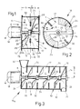
- Fig. 1:
- den Längsschnitt durch einen Mischer mit zwei pflugscharartigen Mischwerkzeugen an einer horizontalen Antriebswelle in einem Behälter;
- Fig. 2:
- die Sicht in den Behälter nach Pfeil II in Fig. 1;
- Fig. 3:
- eine andere Ausführung des Mischers mit mehreren Mischwerkzeugen im Längsschnitt;
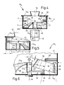
- Fig. 4:
- den Längsschnitt durch einen Mischer mit vertikal verlaufender Antriebswelle;
- Fig. 5, Fig. 6:
- Ausschnitte aus weiteren Ausführungsformen des Mischers.
- Fig. 1:
- the longitudinal section through a mixer with two ploughshare-like mixing tools on a horizontal drive shaft in a container;
- Fig. 2:
- the view into the container according to arrow II in Fig. 1;
- Fig. 3:
- another embodiment of the mixer with several mixing tools in longitudinal section;
- Fig. 4:
- the longitudinal section through a mixer with a vertically extending drive shaft;
- 5, 6:
- Excerpts from further embodiments of the mixer.
Ein Behälter oder Gehäuse 10 aus einem zylindrischen Gehäusemantel 12 sowie scheibenartigen Stirnwänden 14 eines bei 15 gelagerten Mischers 16 zum Vermischen von Sand und Bindemitteln in der Gießerei-Industrie wird in Fig. 1 von einer durch einen Motor 18 angetriebenen, in den Stirnwänden 14 gelagerten Antriebswelle 20 durchsetzt.A container or
Auf der Antriebswelle 20 sitzt ein Tragring 22 für zwei davon radial abragende pflugscharartig geformte Mischwerkzeuge 24, die in den ausgewählten Beispielen jeweils aus einem Radialarm 25 sowie einer gekrümmten Teilringfläche 26 bestehen. Die in Fig. 2 teilkreisförmigen Kanten 27, 28 dieser Mischwerkzeuge 24 erscheinen in Fig. 1 als S-förmige Konturen.On the
Die Außenkante 27 ist in ihrer Form an die ihr benachbarte Innenseite 11 des Gehäusemantels 12 angepaßt. Die Stirnkanten 29 der Mischwerkzeuge 24 verlaufen radial zu jener Antriebswelle 20 nahe der Innenfläche 13 der Stirnwand 14.The shape of the
In einer durch den Tragring 22 gelegten Radialebene E ragen zwischen den beiden propellerartig rotierenden Mischwerkzeugen 24 Einbaukörper 30 - in Richtung der Mischerachse M gesehener --geringer Ausdehnung a von der Gehäuseinnenseite 11 ab. Diese Einbaukörper 30 sind im Ausführungsbeispiel der Fig. 1, 2 von bolzenartigen Teilen der Länge i gebildet, die hier etwas kürzer als der halbe Radius q des Gehäusemantels 12 ist. Der Anstellwinkel zwischen der Achse Q der Einbaukörper 30 und der entsprechenden Tangente t des Gehäusemantels 12, in Fig. 2 mit w bezeichnet, mißt dort etwa 90°.In a radial plane E placed through the
Die beiden Mischwerkzeuge 24 sind, wie vor allem Fig. 1 zu erkennen gibt, auf der Antriebswelle 20 versetzt vorgesehen und befördern das -- aus Gründen der Übersichtlichkeit in der Zeichnung nicht wiedergegebene -- dem chargenweise arbeitenden Mischer 16 durch nicht dargestellte Verschlußelemente im Gehäusemantel 12 oder in den Stirnwänden 14 zugeführte bzw. entnommene Mischgut wechselweise von einem Mischraum A des Mischerraumes 17 auf die andere Seite der Ebene E in einen Mischraum B. Dabei überträgt sich die Rotation (Pfeil x) der Mischwerkzeuge 24 auf das Mischgut. Die äußeren Kanten 27 der Mischwerkzeuge 24 halten die Gehäuseinnenseite 11 in einem in Fig. 1 mit b kenntlich gemachten Bereich anbackungsfrei. Diese Anbackungsfreiheit wird noch begünstigt durch die geringe Ausdehnung a der Einbaukörper 30, wodurch diese geometrisch geringe Hindernisse darstellen.As can be seen above all in FIG. 1, the two
Die Einbaukörper 30 werden vom Mischgut auf dessen Weg von dem einen Mischraum A bzw. B in den anderen Mischraum B bzw. A umströmt und bremsen dabei die Mischgutrotation; es entstehen starke Scheer- und Reibungskräfte, die eine intensive sowie schnelle Vermischung der Mischkomponenten ermöglichen.The material to be mixed flows around the built-in
Mit Anzahl, Querschnitt, Länge i und Anstellwinkel w der Einbaukörper 30 läßt sich die Mischcharakteristik in weitem Umfange beeinflussen.With the number, cross-section, length i and angle of attack w of the
Die in den Fig. 1, 2, 6 dargestellten bolzenartigen Einbaukörper 30 kreisförmigen Querschnittes haben sich z.B. zum Vermischen von Quarzsand mit flüssigen Bindemitteln als besonders geeignet erwiesen. Als Beispiel seien hier Einsatzkörper 30 mit einem Durchmesser d von 20 mm und einer Länge i von 100 mm bei einem Gehäuseradius q von 270 mm als sehr wirkungsvoll herausgestellt.The bolt-
Gemäß Fig. 3 können mehrere Mischwerkzeuge 24 hintereinander axial mit dazwischen angeordneten Einbaukörpern 30 zu einem Durchlaufmischer 16a kombiniert werden. Durch die unterschiedliche Anstellung solcher Mischwerkzeuge 24 oder Mischerschaufeln wird der Mischbewegung eine Transportkomponente von einem Mischereinlaß 32 zu einem Mischgutabwurf 34 überlagert. Die einzelnen Mischgutkomponenten können auch an verschiedenen Stellen des Gehäuses 10 zugeführt werden.According to FIG. 3, a plurality of mixing
Nicht besonders dargestellt ist in der Zeichnung, daß in jedem der Mischräume A, B statt des einen schaufelartigen Mischwerkzeuges 24 deren mehrere angeordnet sein können.It is not particularly shown in the drawing that several can be arranged in each of the mixing spaces A, B instead of the one blade-
Das vorstehend an Mischern 16, 16a mit horizontaler Antriebswelle 20 erläuterte Mischprinzip funktioniert auch in Mischern 16s mit senkrechter Antriebswelle 20 oder auch mit geneigter Antriebswelle. Da bei solchen Mischerausführungen die Schwerkraft das Mischgut nach unten bewegt, ist es hier ausreichend, nach Fig. 4, 5 in einem unteren Mischraum C an einem hier beispielsweise büchsenartigen Tragelement 22a lediglich ein einzelnes, aufwärts angestelltes Mischwerkzeug 24a vorzusehen; der Rücktransport des Mischgutes wird von der Schwerkraft bewirkt. Über einer hier horizontalen Ebene H, die durch die bei dieser Ausführung aus Vierkantstahl hergestellten Einbaukörpern 30 bestimmt ist, liegt ein oberer Mischraum F. Dieser wird durch einen drehenden Abstreifer 36 anbackungsfrei gehalten; der Abstreifer 36 ist so ausgebildet, daß von einem Radialarm 37 der Tragbüchse 22a ein vor Stirnflächen 31 der Einbaukörper 30 aufragender vertikaler Abschnitt 38 ausgeht, an den über jener Ebene H nach einem zweiten Radialarm 37a ein wandungsnaher zweiter Vertikalabschnitt 38a anschließt. Diesem folgt ein zur Mischerachse M weisender Firstarm 39, der sich mit Spiel unterhalb der Innenseite eines Gehäusedeckels 14a bewegt.The mixing principle explained above on
Der vertikale Abschnitt 38 des Abstreifers 36 nimmt bei seiner Bewegung an den Stirnflächen 31 des Einbaukörpers 30 haftendes Mischgut mit. Zudem erteilt der Abstreifer 36 dem im Bereich zwischen den Einbaukörpern 30 abgebremsten Mischgut im oberen Mischraum F eine neue radiale Bewegungskomponente; ehe das Mischgut zurück in den unteren Mischraum C fallen kann, wird es nochmals radial verteilt.The
Unterhalb des Abstreifers 36 ragt nahe des Gehäusebodens 14b von der Tragbüchse 22a ein zusätzliches horizontales Rotationsprofil 40 ab, dessen radiale Erstreckung n etwa jener des Radialarmes 37 entspricht. Dieses Rotationsprofil 40 hält den innerhalb der Bewegungsbahn der Mischwerkzeugkante 29 befindlichen Teil der Innenfläche des Gehäusebodens 14b von Anbackungen frei.Below the
In Fig. 5 verbinden konzentrische Ringe 41 die Einbaukörper 30 zu einem siebartigen Strömungskörper, oberhalb dessen ein Teil 37a, 38a des Abstreifers 36 und unter dem das Mischwerkzeug 24a umläuft.In Fig. 5
Zum Verteilen viskoser Medien auf der Oberfläche körniger Stoffe hat sich besonders die Mischausführung 16v der Fig. 6 bewährt, bei der zusätzlich zu den bereits beschriebenen Teilen eine Rolle 42 an einem radialen Tragarm 43 der Tragbüchse 22a angebracht ist. Die Achse K der Rolle 42 schließt mit der Mischerachse M einen Winkel w₁ ein, und die konische Umfangsfläche 44 der Rolle 42 begrenzt mit dem Gehäusemantel 12 einen kleineren spitzen Winkel w₂.For the distribution of viscous media on the surface of granular materials, the
Unter dem Tragarm 43 hängt eine Schürze 45 als Mischgutmitnehmer zum Gehäuseboden 14a hinab.Under the
Bei Rotation des Mischläufers 50 aus Tragbüchse 22a, Mischwerkzeug 24a, Tragarm 43 und Rolle 42 führt letztere durch die auf sie wirkenden Reibungskräfte eine zusätzliche Eigenrotation aus. Hierdurch wird die Verteilung viskoser Medien auf der Oberfläche körniger Stoffe verbessert. Die dargestellten Winkel w₁, w₂ erzwingen eine zusätzliche räumliche Umschichtung des Mischgutes.When the
Nur angedeutet sind in Fig. 6 Erhebungen 46 bzw. Vertiefungen 48 in der Umfangsfläche 44 der Rolle 42; derartige Retentionen steigern die auf das Mischgut wirkenden Quetsch- und Scheerkräfte erheblich.6,
Eine obere Stirnfläche 52 der Rolle 42 soll zu den Einbaukörpern 30 in einem geringen Abstand h stehen; die Drehung jenes Mischläufers 50 bewirkt in Überlagerung mit der Eigenrotation der Rolle 42, daß an der Stirnfläche 52 haftendes Mischgut von dieser entfernt wird.An upper end face 52 of the
Bei den Ausführungsbeispielen 16s und 16v der Fig. 4 bis 6 ist es denkbar, mehrere Ebenen gleicher Bauart -- wie in Fig. 3 in horizontaler Richtung -- vertikal hintereinander zu reihen, auf jeder dieser Ebenen können an der Antriebswelle 20 auch mehrere Mischwerkzeuge 24a und Abstreifer 36 bzw. Mischläufer 50 vorgesehen sein.In the
Nicht dargestellt ist in der Zeichnung, daß das Gehäuse bzw. der Behälter 10 auch nichtzylindrisch gestaltet sein kann.It is not shown in the drawing that the housing or the
Claims (15)
dadurch gekennzeichnet,
daß in wellenparallelem Abstand vom freien Ende (29) des drehbaren Mischwerkzeuges (24, 24a) von der Wandung (12) des Behälters (10) Einbaukörper (30) mit geringer seitlicher Erstreckung (a, d) abragen.Device for mixing foundry molding materials, in particular sand and binder, with a mixing tool protruding from a drive shaft and rotatable with it into a container,
characterized,
that at a distance parallel to the shaft from the free end (29) of the rotatable mixing tool (24, 24 a ) protrude from the wall (12) of the container (10) installation body (30) with a small lateral extent (a, d).
Applications Claiming Priority (2)
| Application Number | Priority Date | Filing Date | Title |
|---|---|---|---|
| DE4006846A DE4006846A1 (en) | 1990-03-05 | 1990-03-05 | DEVICE FOR MIXING FOUNDRY MOLDING MATERIALS |
| DE4006846 | 1990-03-05 |
Publications (3)
| Publication Number | Publication Date |
|---|---|
| EP0445436A2 true EP0445436A2 (en) | 1991-09-11 |
| EP0445436A3 EP0445436A3 (en) | 1992-04-22 |
| EP0445436B1 EP0445436B1 (en) | 1996-05-22 |
Family
ID=6401439
Family Applications (1)
| Application Number | Title | Priority Date | Filing Date |
|---|---|---|---|
| EP90125711A Expired - Lifetime EP0445436B1 (en) | 1990-03-05 | 1990-12-28 | Apparatus for mixing foundry moulding materials |
Country Status (5)
| Country | Link |
|---|---|
| US (1) | US5393138A (en) |
| EP (1) | EP0445436B1 (en) |
| JP (1) | JP2902798B2 (en) |
| AT (1) | ATE138300T1 (en) |
| DE (2) | DE4006846A1 (en) |
Cited By (3)
| Publication number | Priority date | Publication date | Assignee | Title |
|---|---|---|---|---|
| EP0761295A1 (en) * | 1995-09-12 | 1997-03-12 | List Ag | Mixing kneader |
| EP1745872A2 (en) * | 2005-06-24 | 2007-01-24 | Klein Anlagenbau AG | Process for handling foundry moulding materials |
| EP2790823A1 (en) * | 2011-12-15 | 2014-10-22 | Valmet AB | Mixing unit for use in a mixing apparatus and a mixing apparatus |
Families Citing this family (10)
| Publication number | Priority date | Publication date | Assignee | Title |
|---|---|---|---|---|
| DE19521130C2 (en) * | 1994-06-16 | 2000-06-15 | Graemer Gerd Volker | Device for mixing a granular material with a liquid |
| ATE487537T1 (en) * | 2005-12-07 | 2010-11-15 | Lico Spa | APPARATUS AND METHOD FOR CONTINUOUS HORIZONTAL MIXING |
| JP5646491B2 (en) * | 2009-09-04 | 2014-12-24 | 株式会社ツカサ | Powder and agitation equipment |
| WO2011044940A1 (en) * | 2009-10-15 | 2011-04-21 | Bühler AG | Centrifugal mixer, method and use for comminution |
| ES2579236T3 (en) * | 2009-10-15 | 2016-08-08 | Bühler AG | Method and use to refine |
| FI126111B (en) * | 2012-05-07 | 2016-06-30 | Maricap Oy | Method and device for feeding material into a rotary machining device |
| DE102013219061B3 (en) * | 2013-09-23 | 2014-10-02 | Klein Anlagenbau Ag | mixing tool |
| JP5718511B1 (en) * | 2014-06-17 | 2015-05-13 | 株式会社清田鋳機 | Cleaning method of continuous mixer for foundry sand |
| CN105413512A (en) * | 2015-11-30 | 2016-03-23 | 天津威晟番茄制品有限公司 | Stirring device of tomato sauce packing machine |
| CN106424546A (en) * | 2016-11-09 | 2017-02-22 | 郑州莉迪亚医药科技有限公司 | Precoated sand processing device |
Citations (8)
| Publication number | Priority date | Publication date | Assignee | Title |
|---|---|---|---|---|
| US1645990A (en) * | 1922-11-21 | 1927-10-18 | Baker Perkins Co Inc | Vessel for mixing chocolate and similar substances |
| US2413603A (en) * | 1944-05-10 | 1946-12-31 | Herbert S Simpson | Mixer |
| FR2011198A1 (en) * | 1968-06-19 | 1970-02-27 | Badische Maschf Gmbh | Foundry sand mixture |
| DE3613612A1 (en) * | 1985-04-30 | 1986-11-06 | Gumix S.A., Barcelona | TURBOMIC EXTRUSION |
| DE3639432A1 (en) * | 1985-12-31 | 1987-07-02 | Keramikmaschinen Goerlitz Veb | Appliance for pressing down and lifting out of edge runners in mixers |
| EP0279255A1 (en) * | 1987-02-03 | 1988-08-24 | CARLE & MONTANARI S.p.A. | Apparatus for decreasing viscosity in suspensions from solids in fat carrier like chocolate masses |
| EP0303728A1 (en) * | 1987-08-21 | 1989-02-22 | Schumacher, Walter Dr. Ing. | Apparatus for extruding, expanding and/or thermally processing materials or material blends |
| DE3914694A1 (en) * | 1988-07-04 | 1990-01-11 | Sanyo Chemical Ind Ltd | STIRRING DEVICE |
Family Cites Families (17)
| Publication number | Priority date | Publication date | Assignee | Title |
|---|---|---|---|---|
| NL71608C (en) * | ||||
| FR625884A (en) * | 1927-08-22 | |||
| US1546335A (en) * | 1922-05-09 | 1925-07-14 | Barber Asphalt Co | Mixing machinery |
| US2029690A (en) * | 1933-07-10 | 1936-02-04 | Standard Oil Co | Process and apparatus for contacting two liquids |
| US2082796A (en) * | 1934-12-21 | 1937-06-08 | Gaertner Moritz | Agitator |
| US2227522A (en) * | 1939-08-19 | 1941-01-07 | Anderson Co V D | Combined agitator and conveyer mechanism |
| US2626786A (en) * | 1947-05-05 | 1953-01-27 | Leonard D Mcglothlin | Automatic consistency control means |
| GB635376A (en) * | 1947-08-14 | 1950-04-05 | Donald Gwilliam Price | Improvements in and relating to the mixing or blending of powdered or granular substances |
| DE1075561B (en) * | 1953-09-15 | 1960-02-18 | zugl | Mixing and kneading machine |
| DE1173787B (en) * | 1958-09-16 | 1964-07-09 | Ferdinand Wultsch Dipl Ing Dr | Device for breaking up cellulose fiber bundles into individual fibers |
| FR2302774A1 (en) * | 1975-03-03 | 1976-10-01 | Sapic | PROCESS AND PLANT FOR PREPARING A MIXTURE FOR FOUNDRY OR SIMILAR MOLDS, WITH FORMATION OF A PREMIX |
| US3980013A (en) * | 1975-09-15 | 1976-09-14 | The French Oil Mill Machinery Company | Split worm for screw press |
| CH602172A5 (en) * | 1975-10-10 | 1978-07-31 | Fischer Ag Georg | |
| US4194925A (en) * | 1977-08-15 | 1980-03-25 | Columbia Machine, Inc. | Method and apparatus for washing mixing containers |
| US4155657A (en) * | 1978-03-10 | 1979-05-22 | Chemed Corporation | Continuous mixer for preparing emulsions |
| DE8234900U1 (en) * | 1981-12-18 | 1983-03-24 | Lüber, Werner, Bazenheid | ROTARY MIXING DEVICE FOR GRANULAR GOETER, ESPECIALLY CORE SAND |
| DE3818453A1 (en) * | 1988-05-31 | 1989-12-07 | Janke & Kunkel Kg | DISPERSING MACHINE |
-
1990
- 1990-03-05 DE DE4006846A patent/DE4006846A1/en active Granted
- 1990-12-28 EP EP90125711A patent/EP0445436B1/en not_active Expired - Lifetime
- 1990-12-28 AT AT90125711T patent/ATE138300T1/en not_active IP Right Cessation
- 1990-12-28 DE DE59010341T patent/DE59010341D1/en not_active Expired - Lifetime
-
1991
- 1991-02-18 JP JP3045805A patent/JP2902798B2/en not_active Expired - Fee Related
-
1993
- 1993-02-09 US US08/015,453 patent/US5393138A/en not_active Expired - Lifetime
Patent Citations (8)
| Publication number | Priority date | Publication date | Assignee | Title |
|---|---|---|---|---|
| US1645990A (en) * | 1922-11-21 | 1927-10-18 | Baker Perkins Co Inc | Vessel for mixing chocolate and similar substances |
| US2413603A (en) * | 1944-05-10 | 1946-12-31 | Herbert S Simpson | Mixer |
| FR2011198A1 (en) * | 1968-06-19 | 1970-02-27 | Badische Maschf Gmbh | Foundry sand mixture |
| DE3613612A1 (en) * | 1985-04-30 | 1986-11-06 | Gumix S.A., Barcelona | TURBOMIC EXTRUSION |
| DE3639432A1 (en) * | 1985-12-31 | 1987-07-02 | Keramikmaschinen Goerlitz Veb | Appliance for pressing down and lifting out of edge runners in mixers |
| EP0279255A1 (en) * | 1987-02-03 | 1988-08-24 | CARLE & MONTANARI S.p.A. | Apparatus for decreasing viscosity in suspensions from solids in fat carrier like chocolate masses |
| EP0303728A1 (en) * | 1987-08-21 | 1989-02-22 | Schumacher, Walter Dr. Ing. | Apparatus for extruding, expanding and/or thermally processing materials or material blends |
| DE3914694A1 (en) * | 1988-07-04 | 1990-01-11 | Sanyo Chemical Ind Ltd | STIRRING DEVICE |
Cited By (5)
| Publication number | Priority date | Publication date | Assignee | Title |
|---|---|---|---|---|
| EP0761295A1 (en) * | 1995-09-12 | 1997-03-12 | List Ag | Mixing kneader |
| EP1745872A2 (en) * | 2005-06-24 | 2007-01-24 | Klein Anlagenbau AG | Process for handling foundry moulding materials |
| EP1745872A3 (en) * | 2005-06-24 | 2009-03-11 | Klein Anlagenbau AG | Process for handling foundry moulding materials |
| EP2790823A1 (en) * | 2011-12-15 | 2014-10-22 | Valmet AB | Mixing unit for use in a mixing apparatus and a mixing apparatus |
| EP2790823A4 (en) * | 2011-12-15 | 2015-07-08 | Valmet Oy | Mixing unit for use in a mixing apparatus and a mixing apparatus |
Also Published As
| Publication number | Publication date |
|---|---|
| DE4006846C2 (en) | 1992-10-22 |
| JPH04224042A (en) | 1992-08-13 |
| ATE138300T1 (en) | 1996-06-15 |
| DE4006846A1 (en) | 1991-09-12 |
| DE59010341D1 (en) | 1996-06-27 |
| US5393138A (en) | 1995-02-28 |
| EP0445436B1 (en) | 1996-05-22 |
| JP2902798B2 (en) | 1999-06-07 |
| EP0445436A3 (en) | 1992-04-22 |
Similar Documents
| Publication | Publication Date | Title |
|---|---|---|
| EP0445436B1 (en) | Apparatus for mixing foundry moulding materials | |
| DE1075561B (en) | Mixing and kneading machine | |
| CH412812A (en) | Device for the treatment of flowable substances and mixtures of substances | |
| DE10110910C1 (en) | Mixer, used in production of pasty products, e.g. creams, ointments and emulsions, comprises mixing container, and outer/inner stirrer in container that rotates about symmetrical axis of container using drive | |
| DE3635877C1 (en) | Mixer dryer | |
| DE1204632B (en) | Pan mixer | |
| EP0211230B1 (en) | Installation for mixing solid materials and liquids | |
| DE1211904B (en) | Agitator mill | |
| DE1245690B (en) | Grinding device | |
| DE2146611A1 (en) | REFRIGERATOR | |
| DE1941831A1 (en) | Tank mixer | |
| DE19521130C2 (en) | Device for mixing a granular material with a liquid | |
| CH444739A (en) | Device for mixing liquids from powdery to granular materials | |
| DE3105558A1 (en) | Chopper appliance for a conical screw mixer | |
| DE3641413C1 (en) | Apparatus for processing materials | |
| DE2043608C2 (en) | Pan mixer | |
| AT218943B (en) | Mixer with a mixing bowl rotating around a vertical axis | |
| DE2336699C2 (en) | Device for mixing building materials | |
| DE1557223B2 (en) | Device for dispersing gases and / or liquids and / or solids in liquids | |
| DE2739106C2 (en) | Apparatus for stirring a liquid containing solid particles | |
| DE1194375B (en) | Pan mixer | |
| DE1141517B (en) | Device for crushing, mixing and homogenizing substances and for carrying out mechano-chemical reactions | |
| DE1557223C (en) | Device for dispersing gases and / or liquids and / or solids in liquids excretion from 1295524 | |
| DE19835347A1 (en) | Chocolate conch with twin parallel agitators, running in close proximity to provide shear and kneading action | |
| DE1954563C (en) | Device for mixing debris well, especially plastic Rohma th al |
Legal Events
| Date | Code | Title | Description |
|---|---|---|---|
| PUAI | Public reference made under article 153(3) epc to a published international application that has entered the european phase |
Free format text: ORIGINAL CODE: 0009012 |
|
| AK | Designated contracting states |
Kind code of ref document: A2 Designated state(s): AT BE CH DE DK ES FR GB GR IT LI LU NL SE |
|
| PUAL | Search report despatched |
Free format text: ORIGINAL CODE: 0009013 |
|
| AK | Designated contracting states |
Kind code of ref document: A3 Designated state(s): AT BE CH DE DK ES FR GB GR IT LI LU NL SE |
|
| 17P | Request for examination filed |
Effective date: 19920610 |
|
| RBV | Designated contracting states (corrected) |
Designated state(s): AT CH DE FR GB IT LI NL |
|
| 17Q | First examination report despatched |
Effective date: 19930709 |
|
| GRAH | Despatch of communication of intention to grant a patent |
Free format text: ORIGINAL CODE: EPIDOS IGRA |
|
| GRAH | Despatch of communication of intention to grant a patent |
Free format text: ORIGINAL CODE: EPIDOS IGRA |
|
| GRAH | Despatch of communication of intention to grant a patent |
Free format text: ORIGINAL CODE: EPIDOS IGRA |
|
| GRAA | (expected) grant |
Free format text: ORIGINAL CODE: 0009210 |
|
| AK | Designated contracting states |
Kind code of ref document: B1 Designated state(s): AT CH DE FR GB IT LI NL |
|
| PG25 | Lapsed in a contracting state [announced via postgrant information from national office to epo] |
Ref country code: IT Free format text: LAPSE BECAUSE OF FAILURE TO SUBMIT A TRANSLATION OF THE DESCRIPTION OR TO PAY THE FEE WITHIN THE PRESCRIBED TIME-LIMIT;WARNING: LAPSES OF ITALIAN PATENTS WITH EFFECTIVE DATE BEFORE 2007 MAY HAVE OCCURRED AT ANY TIME BEFORE 2007. THE CORRECT EFFECTIVE DATE MAY BE DIFFERENT FROM THE ONE RECORDED. Effective date: 19960522 |
|
| REF | Corresponds to: |
Ref document number: 138300 Country of ref document: AT Date of ref document: 19960615 Kind code of ref document: T |
|
| REF | Corresponds to: |
Ref document number: 59010341 Country of ref document: DE Date of ref document: 19960627 |
|
| GBT | Gb: translation of ep patent filed (gb section 77(6)(a)/1977) |
Effective date: 19960806 |
|
| ET | Fr: translation filed | ||
| PG25 | Lapsed in a contracting state [announced via postgrant information from national office to epo] |
Ref country code: AT Effective date: 19961228 |
|
| PG25 | Lapsed in a contracting state [announced via postgrant information from national office to epo] |
Ref country code: LI Effective date: 19961231 Ref country code: CH Effective date: 19961231 |
|
| PLBE | No opposition filed within time limit |
Free format text: ORIGINAL CODE: 0009261 |
|
| STAA | Information on the status of an ep patent application or granted ep patent |
Free format text: STATUS: NO OPPOSITION FILED WITHIN TIME LIMIT |
|
| 26N | No opposition filed | ||
| REG | Reference to a national code |
Ref country code: CH Ref legal event code: PL |
|
| PGFP | Annual fee paid to national office [announced via postgrant information from national office to epo] |
Ref country code: NL Payment date: 20001221 Year of fee payment: 11 |
|
| REG | Reference to a national code |
Ref country code: FR Ref legal event code: TP |
|
| REG | Reference to a national code |
Ref country code: GB Ref legal event code: IF02 |
|
| PG25 | Lapsed in a contracting state [announced via postgrant information from national office to epo] |
Ref country code: NL Free format text: LAPSE BECAUSE OF NON-PAYMENT OF DUE FEES Effective date: 20020701 |
|
| NLV4 | Nl: lapsed or anulled due to non-payment of the annual fee |
Effective date: 20020701 |
|
| PGFP | Annual fee paid to national office [announced via postgrant information from national office to epo] |
Ref country code: GB Payment date: 20051122 Year of fee payment: 16 |
|
| PGFP | Annual fee paid to national office [announced via postgrant information from national office to epo] |
Ref country code: FR Payment date: 20051216 Year of fee payment: 16 |
|
| GBPC | Gb: european patent ceased through non-payment of renewal fee |
Effective date: 20061228 |
|
| REG | Reference to a national code |
Ref country code: FR Ref legal event code: ST Effective date: 20070831 |
|
| PG25 | Lapsed in a contracting state [announced via postgrant information from national office to epo] |
Ref country code: GB Free format text: LAPSE BECAUSE OF NON-PAYMENT OF DUE FEES Effective date: 20061228 |
|
| PG25 | Lapsed in a contracting state [announced via postgrant information from national office to epo] |
Ref country code: FR Free format text: LAPSE BECAUSE OF NON-PAYMENT OF DUE FEES Effective date: 20070102 |
|
| PGFP | Annual fee paid to national office [announced via postgrant information from national office to epo] |
Ref country code: DE Payment date: 20100222 Year of fee payment: 20 |
|
| PG25 | Lapsed in a contracting state [announced via postgrant information from national office to epo] |
Ref country code: DE Free format text: LAPSE BECAUSE OF EXPIRATION OF PROTECTION Effective date: 20101228 |