EP0444654B1 - Appareil à jet d'encre - Google Patents
Appareil à jet d'encre Download PDFInfo
- Publication number
- EP0444654B1 EP0444654B1 EP91102965A EP91102965A EP0444654B1 EP 0444654 B1 EP0444654 B1 EP 0444654B1 EP 91102965 A EP91102965 A EP 91102965A EP 91102965 A EP91102965 A EP 91102965A EP 0444654 B1 EP0444654 B1 EP 0444654B1
- Authority
- EP
- European Patent Office
- Prior art keywords
- ink
- supply passage
- iju
- container
- ink jet
- Prior art date
- Legal status (The legal status is an assumption and is not a legal conclusion. Google has not performed a legal analysis and makes no representation as to the accuracy of the status listed.)
- Expired - Lifetime
Links
Images


Classifications
-
- B—PERFORMING OPERATIONS; TRANSPORTING
- B41—PRINTING; LINING MACHINES; TYPEWRITERS; STAMPS
- B41J—TYPEWRITERS; SELECTIVE PRINTING MECHANISMS, i.e. MECHANISMS PRINTING OTHERWISE THAN FROM A FORME; CORRECTION OF TYPOGRAPHICAL ERRORS
- B41J2/00—Typewriters or selective printing mechanisms characterised by the printing or marking process for which they are designed
- B41J2/005—Typewriters or selective printing mechanisms characterised by the printing or marking process for which they are designed characterised by bringing liquid or particles selectively into contact with a printing material
- B41J2/01—Ink jet
- B41J2/135—Nozzles
- B41J2/165—Preventing or detecting of nozzle clogging, e.g. cleaning, capping or moistening for nozzles
- B41J2/16517—Cleaning of print head nozzles
- B41J2/1652—Cleaning of print head nozzles by driving a fluid through the nozzles to the outside thereof, e.g. by applying pressure to the inside or vacuum at the outside of the print head
- B41J2/16523—Waste ink collection from caps or spittoons, e.g. by suction
-
- B—PERFORMING OPERATIONS; TRANSPORTING
- B41—PRINTING; LINING MACHINES; TYPEWRITERS; STAMPS
- B41J—TYPEWRITERS; SELECTIVE PRINTING MECHANISMS, i.e. MECHANISMS PRINTING OTHERWISE THAN FROM A FORME; CORRECTION OF TYPOGRAPHICAL ERRORS
- B41J2/00—Typewriters or selective printing mechanisms characterised by the printing or marking process for which they are designed
- B41J2/005—Typewriters or selective printing mechanisms characterised by the printing or marking process for which they are designed characterised by bringing liquid or particles selectively into contact with a printing material
- B41J2/01—Ink jet
- B41J2/17—Ink jet characterised by ink handling
- B41J2/175—Ink supply systems ; Circuit parts therefor
- B41J2/17503—Ink cartridges
- B41J2/17513—Inner structure
-
- B—PERFORMING OPERATIONS; TRANSPORTING
- B41—PRINTING; LINING MACHINES; TYPEWRITERS; STAMPS
- B41J—TYPEWRITERS; SELECTIVE PRINTING MECHANISMS, i.e. MECHANISMS PRINTING OTHERWISE THAN FROM A FORME; CORRECTION OF TYPOGRAPHICAL ERRORS
- B41J2/00—Typewriters or selective printing mechanisms characterised by the printing or marking process for which they are designed
- B41J2/005—Typewriters or selective printing mechanisms characterised by the printing or marking process for which they are designed characterised by bringing liquid or particles selectively into contact with a printing material
- B41J2/01—Ink jet
- B41J2/17—Ink jet characterised by ink handling
- B41J2/175—Ink supply systems ; Circuit parts therefor
- B41J2/17563—Ink filters
Definitions
- the present invention relates to an ink jet recording head cartridge having a recording head provided with an ink ejector (discharger) for ejecting (discharging) ink and an ink container as a unit and to an ink jet recording apparatus having the cartridge.
- an ink jet recording head cartridge having a recording head provided with an ink ejector (discharger) for ejecting (discharging) ink and an ink container as a unit and to an ink jet recording apparatus having the cartridge.
- the first and second type are such that the recording head is fixed on the apparatus therefore, when an error occurs in the head, maintenance servicing is required with the result of larger out-of-use period.
- the ink is supplied from the ink container through an ink supply tube.
- the third type recording head is advantageous from the standpoint of avoiding the above problems.
- the third type therefore, is desirable because of the small size, low cost and reduction of non-usable period.
- FIG. 1 there is shown, in a cross-section, an example of ink jet recording head in the form of a cartridge with an integral ink container.
- Figure 2 is a cross-section of a major part of another example of an ink jet recording head in the form of a cartridge.
- the head comprises a head chip 400a constituting an ink ejector and an ink container.
- the head chip 400a has ink passages communicating with ink ejection (discharging) outlets 111.
- energy generating elements for generating energy for ejecting the ink (for example, electrothermal transducers for causing film boiling).
- a common ink chamber 401a communicates with the ink passages and is supplied with the ink from an ink container 1000 through an ink supply passage 1600a.
- An air vent 100a is provided in the ink container.
- a mesh filter 700 is provided in the connection between the head chip 400a and the ink container 1000 to prevent introduction of foreign matter or air bubbles possibly existing in the ink container 1000 into the head chip 401a.
- the filter 700 is mounted when the separate ink container 1000 and head chip 400a are joined together, because of easy manufacturing.
- the ink container 1000 contains an ink absorbing material made of porous, fibrous or continuous porous material, which absorbs and retains the ink.
- the absorber 900 is compressed to a proper extent so that the retaining capacity is increased. It is effective to assure a predetermined negative pressure at the ink ejection outlets to permit the meniscus in the ink ejection outlet being retracted to a proper extent. By this, the ink is prevented from leaking out through the ejection outlets. In the case where the ejection outlets are oriented downwardly in use, it is effective to prevent the ink leakage.
- the recording head having the structure still has the problems which will be described in the following paragraphs.
- the recording head alone or the recording head mounted in the recording apparatus is left unused for a long period of time, a bubble or bubbles may be produced in the ink due to evaporation of the solvent of the ink and the dissolved gasses. If it is further left unused, the evaporation proceeds even to such an extent that the bubble is developed to evacuate of the ink in the ink supply passage 1600a. If the bubble is stagnated in the ink passage 401, the supply of the ink is disturbed with the result of improper ink ejection. In order to avoid this by permitting the ink supply even upon the of the bubbles occuring more or less production, the cross-sectional area of the ink supply passage 1600a is made large.
- the inside volume of the ink passage of the ink jet recording head becomes large. Then, a large capacity sucking pump is required to permit sucking recovery when the inside of the ink ejector 400a lacks the ink by the long term non-use or by the ink dropping out.
- the capacity of the pump is small, it would be possible to suck the ink in the middle of the ink passage of the recording head. This, however, is not enough, because the ink is retracted by the vacuum of the absorbing material 900, so that the recording head is not filled with the ink even if the sucking operation is repeated.
- an ink jet recording apparatus which comprises a suction pump selectively connectable to a cap for capping ejection ports of a recording head via a valve arranged at the suction line between a sucking pump and the cap.
- the pump can be operated for several subsequent suction operations in order to flush or rinse the ejection outlets for several times.
- This apparatus requires an additional valve to be arrranged and additional control effort for the valve so that this recovery system renders the ink jet recording apparatus bulky and heavy.
- a jet printing apparatus which comprises an hour-glass tube arranged at the outlet of an ink tank from which the ink is conducted to a recording head.
- the hour-glass tube cooperates with a wound up long supply pipe in order to damp resonance frequencies in the ink column. Due to the voluminuos ink supply system, this apparatus is also rendered bulky an heavy.
- the object is, with respect to the apparatus, solved with an apparatus having the features of one of claims 1, 3 and 5; the object regarding the recording head is solved with an ink jet recording head having the features of one of claims 8, 10 and 12.
- Figure 1 is a sectional view of a recording head.
- Figure 2 is a sectional view of a recording head wherein a part of the ink is dropped out.
- Figure 3A is an exploded perspective view of an example of an ink jet cartridge according to an embodiment of the present invention.
- Figure 3B is a perspective view of an ink jet cartridge according to an embodiment of the present invention.
- Figure 4 is a perspective view of an ink container of an ink jet recording cartridge as seen from the ink jet recording head mounting side.
- Figure 5 is a top plan view of the ink jet cartridge which is being mounted on a carriage of the main assembly of the ink jet recording apparatus.
- Figure 6 is a perspective view of an ink jet recording apparatus.
- Figures 7A and 7B are perspective views illustrating ink supply system.
- Figure 7C is a partly broken front view of an ink supply system of the ink jet unit according to an embodiment of the present invention.
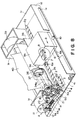
- Figure 8 is a partly broken side view of an example of an ink jet recording apparatus.
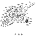
- Figure 9 is an exploded perspective view of a recovery system including a sucking pump which is a forced ink discharging means according to an embodiment of the present invention.
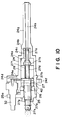
- Figure 10 is a sectional view of a recovery system including a sucking pump which is a forced ink discharging means, according to an embodiment of the present invention.
- Figures 11A, 11B and 11C are plan views illustrating the positional relationship between the recording head and members acting thereon during a preliminary ejection period, a capping period and a sucking recovery period.
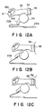
- Figures 12A, 12B and 12C are side views illustrating the sequential operation of the sequential capping operation.
- Figures 13A and 13B are sectional views illustrating operation of the sucking recovery pump.
- Figures 14A, 14B and 14C are sectional views of the ink jet cartridge in a normal condition, in the ink drop-out condition and in the insufficient ink condition, illustrating the filling of the ink in the ink jet cartridge, according to an embodiment of the present invention.
- Figure 15 is a graph of a vacuum in the pump vs. time during the pump sucking operation.
- Figures 16A, 16B and 16C are sectional views of an ink jet cartridge in a normal state, upon completion of the sucking operation, and in the ink drop-out state, according to an embodiment of the present invention.
- Figure 17 is a sectional view of a part of an ink jet recording head, according to another embodiment of the present invention.
- Figures 18A and 18B are sectional views of a major part of the ink jet recording head according to a further embodiment of the present invention.
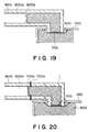
- Figure 19 is a partial sectional view of a major part of the ink jet recording head according to a further embodiment of the present invention.
- Figure 20 is a partial sectional view of a major part according to a further embodiment of the present invention.
- Figure 21 is a sectional view of a recording head having an integral ink container, according to a further embodiment of the present invention.
- Figure 22 is a sectional view illustrating assembling of the recording head of Figure 21.
- Figure 23 is a perspective view illustrating an outer appearance thereof.
- Figures 24 and 25 are a perspective view and a top plan view illustrating the mounting portion of the recording apparatus for receiving the recording head shown in Figure 23.
- Figure 26 is a perspective view illustrating an ink jet recording apparatus according to a further embodiment of the present invention.
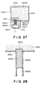
- Figures 27 and 28 are sectional views of a recording head according to a further embodiment of the present invention.
- Figures 3A, 3B, 4, 5 and 6 illustrate an ink jet unit IJU, an ink jet heat IJH, an ink container IT, an ink jet cartridge IJC, a head carriage HC and a main assembly IJRA of an ink jet recording apparatus, according to an embodiment of the present invention, and relations among them.
- the structures of the respective elements will be described in the following.
- the ink jet cartridge IJC in this embodiment has a relatively large ink accommodation space, and an end portion of the ink jet unit IJU is slightly projected from the front side surface of the ink container IT.
- the ink jet cartridge IJC is mountable at a correct position on the carriage HC ( Figure 5) of the ink jet recording apparatus main assembly IJRA by proper positioning means and with electric contacts, which will be described in detail hereinafter. It is, in this embodiment, a disposable type head detachably mountable on the carriage AC.
- the ink jet unit IJU is of an ink jet recording type using electrothermal transducers which generate thermal energy, in response to electric signals, to produce film boiling of the ink.
- the unit comprises a heater board 100 having electrothermal transducers (ejection heaters) arranged in a line on an Si substrate and electric lead lines made of aluminum or the like to supply electric power thereto.
- the electrothermal transducer and the electric leads are formed by a film forming process.
- a wiring board 200 is associated with the heater board 100 and includes wiring corresponding to the wiring of the heater board 100 (connected by the wire bonding technique, for example) and pads 201 disposed at an end of the wiring to receive electric signals from the main assembly of the recording apparatus.
- a top plate 1300 is provided with grooves which define partition walls for separating adjacent ink passages and a common liquid chamber for accommodating the ink to be supplied to the respective ink passages.
- the top plate 1300 is formed integrally with an ink jet opening 1500 for receiving the ink supplied from the ink container IT and directing the ink to the common chamber, and also with an orifice plate 400 having the plurality of ejection outlets corresponding to the ink passages.
- the material of the integral mold is preferably polysulfone, but may be another molding resin material.
- a supporting member 300 is made of metal, for example, and functions to support a back side of the wiring board 200 in a plane, and constitutes a bottom plate of the ink jet unit IJU.
- a confining spring 500 is in the form of "M" having a central portion urging to the common chamber with a light pressure, and a clamp 501 urges concentratedly with a line pressure to a part of the liquid passage, preferably the part in the neighborhood of the ejection outlets.
- the confining spring 500 has legs for clamping the heater board 100 and the top plate 1300 by penetrating through the openings 3121 of the supporting plate 300 and engaging the back surface of the supporting plate 300.
- the supporting plate 300 has positioning openings 312, 1900 and 2000 engageable with two positioning projections 1012, and positioning and fuse-fixing projections 1800 and 1801 of the ink container IT. It further includes projections 2500 and 2600 at its back side for the positioning relative to the carriage HC of the main assembly IJRA.
- the supporting member 300 has a hole 320 through which an ink supply pipe 2200, which will be described hereinafter, is penetrated for supplying ink from the ink container.
- the wiring board 200 is mounted on the supporting member 300 by bonding agent or the like.
- the supporting member 300 is provided with recesses 2400 and 2400 adjacent the positioning projections 2500 and 2600.
- the assembled ink jet cartridge IJC has a head projected portion having three sides provided with plural parallel grooves 3000 and 3001.
- the recesses 2400 and 2400 are located at extensions of the parallel grooves at the top and bottom sides to prevent the ink or foreign matter moving along the groove from reaching the projections 2500 and 2600.
- the covering member 800 having the parallel grooves 3000 constitutes an outer casing of the ink jet cartridge IJC and cooperates with the ink container to define a space for accommodating the ink jet unit IJU.
- the ink supply member 600 having the parallel groove 3001 has an ink conduit pipe 1600 communicating with the above-described ink supply pipe 2200 and cantilevered at the supply pipe 2200 side. In order to assure the capillary action at the fixed side of the ink conduit pipe 1600 and the ink supply pipe 2200, a sealing pin 602 is inserted.
- a gasket 601 seals the connecting portion between the ink container IT and the supply pipe 2200.
- a filter 700 is disposed at the container side end of the supply pipe.
- the ink supply member 600 is molded, and therefore, it is produced at low cost with high positional accuracy.
- the cantilevered structure of the conduit 1600 assures the press-contact between the conduit 1600 and the ink inlet 1500 even if the ink supply member 600 is mass-produced.
- the complete communicating state can be assuredly obtained simply by flowing sealing bonding agent from the ink supply member side under press-contacted state.
- the ink supply member 600 may be fixed to the supporting member 300 by inserting and penetrating back side pins (not shown) of the ink supply member 600 through the openings 1901 and 1902 of the supporting member 300 and by heat-fusing the portion where the pins are projected through the backside of the supporting member 300.
- the slight projected portions thus heat-fused are accommodated in recesses (not shown) in the ink jet unit (IJU) mounting side surface of the ink container IT, and therefore, the unit IJU can be correctly positioned.
- the ink container comprises a main body 1000, an ink absorbing material and a cover member 1100.
- the ink absorbing material 900 is inserted into the main body 1000 from the side opposite from the unit (IJU) mounting side, and thereafter, the cover member 1100 seals the main body.
- the ink absorbing material 900 is thus disposed in the main body 1000.
- the ink supply port 1200 functions to supply the ink to the ink jet unit IJU comprising the above-described parts 100 - 600, and also functions as an ink injection inlet to permit initial ink supply to the absorbing material 900 before the unit IJU is mounted to the portion 1010 of the main body.
- the ink may be supplied through an air vent port and this supply opening.
- ribs 2300 is formed on the inside surface of the main body 1000, and ribs 2301 and 2302 are formed on the inside of the cover member 1100, which are effective to provide within the ink container an ink existing region extending continuously from the air vent port side to that corner portion of the main body which is most remote from the ink supply opening 1200. Therefore, in order to uniformly distribute the ink in good order, it is preferable that the ink is supplied through the supply opening 1200. This ink supply method is practically effective.
- the number of the ribs 2300 in this embodiment is four, and the ribs 2300 extend parallel to a movement direction of the carriage adjacent the rear side of the main body of the ink container, by which the absorbing material 900 is prevented from closely contacting to the inner surface of the rear side of the main body.
- the ribs 2301 and 2302 are formed on the inside surface of the cover member 1100 at a position which is substantially an extension of the ribs 2300, however, as contrasted to the large rib 2300, the size of the ribs 2301 and 2302 are small as if it is divided ribs, so that the existing space is larger with the ribs 2301 and 2302 than with the rib 2300.
- the ribs 2302 and 2301 are distributed on the entire area of the cover member 1100, and the area thereof is not more than one half of the total area. Because of the provisions of the ribs, the ink in the corner region of the ink absorbing material which is most remote from the supply opening 1200 can be stably and assuredly supplied to the inlet opening by capillary action.
- the cartridge is provided with an air vent port for communicating the inside of the cartridge with the outside air. Inside the vent port 1400, there is a water repellent material 1400 to prevent the inside ink from leaking outside through the vent port 1400.
- the ink accommodating space in the ink container IT is a substantially rectangular parallelepiped, and the long side faces in the direction of carriage movement, and therefore, the above-described rib arrangements are particularly effective.
- the ribs are preferably formed on the entire surface of the inside of the cover member 1100 to stabilize the ink supply from the ink absorbing material 900.
- the cube configuration is preferable from the standpoint of accommodating as much ink as possible in limited space.
- the provisions of the ribs formed on the two surfaces constituting a corner is advantageous.
- the inside ribs 2301 and 2302 of the ink container IT are substantially uniformly distributed in the direction of the thickness of the ink absorbing material having the rectangular parallelepiped configuration.
- Such a structure is significant, since the air pressure distribution in the ink container IT is made uniform when the ink in the absorbing material is consumed so that the quantity of the remaining unavailable ink is substantially zero.
- the ribs are disposed on the surface or surfaces outside a circular arc having the center at the projected position on the ink supply opening 1200 on the top surface of the rectangular ink absorbing material and having a radius which is equal to the long side of the rectangular shape, since then the ambient air pressure is quickly established for the ink absorbing material present outside the circular arc.
- the position of the air vent of the ink container IT is not limited to the position of this embodiment if it is good for introducing the ambient air into the position where the ribs are disposed.
- the back side of the ink jet cartridge IJC is flat, and therefore, the space required when mounted in the apparatus is minimized, while maintaining the maximum ink accommodating capacity. Therefore, the size of the apparatus can be reduced, and simultaneously, the frequency of the cartridge exchange is minimized.
- a projection for the air vent port 1401 is formed.
- the inside of the projection is substantially vacant, and the vacant space 1402 functions to supply the air into the ink container IT uniformly in the direction of the thickness of the absorbing material. Because of these features described above, the cartridge as a whole is of better performance than a conventional cartridge.
- the air supply space 1402 is much larger than that in a conventional cartridge.
- the air vent port 1401 is at an upper position, and therefore, if the ink departs from the absorbing material for some reason or another, the air supply space 1402 can tentatively retain the ink to permit such ink to be absorbed back into the absorbing material. Therefore, a wasteful consumption of the ink can be avoided.
- FIG. 4 there is shown a structure of a surface of the ink container IT to which the unit IJU is mounted.
- Two positioning projections 1012 are on a line L1 which is a line passing through the substantial center of the array of the ejection outlets in the orifice plate 400 and parallel with the bottom surface of the ink container IT or parallel to the ink container supporting reference surface of the carriage.
- the height of the projections 1012 is slightly smaller than the thickness of the supporting member 300, and the projections 1012 function to correctly position the supporting member 300.
- Projections 1800 and 1801 corresponding to the fixing wholes 1900 and 2000 for fixing the supporting member 300 to the side of the ink container IT are longer than the projections 1012, so that they penetrate through the supporting member 300, and the projected portions are fused to fix the supporting member 300 to the side surface.
- a line L3 passing through the projection 1800 and perpendicular to the line L1 and a line L2 passing through the projection 1801 and perpendicular to the line L1 are drawn.
- the center of the supply opening 1200 is substantially on the line L3, the connection between the supply opening 1200 and a supply type 2200 is stabilized, and therefore, even if the cartridge falls, or even if a shock is imparted to the cartridge, the force applied to the connecting portion can be minimized.
- a curve L4 indicates the position of the outer wall of the ink supply member 600 when it is mounted. Since the projections 1800 and 1801 are along the curve L4, the projections are effective to provide sufficient mechanical strength and positional accuracy against the weight of the end structure of the head IJH.
- An end projection 2700 of the ink container IT is engageable with a whole formed in the front plate 4000 of the carriage to prevent the ink cartridge from being displaced extremely out of the position.
- a stopper 2101 is engageable with an unshown rod of the carriage HC, and when the cartridge IJC is correctly mounted with rotation, which will be described hereinafter, the stopper 2101 take a position below the rod, so that even if an upward force tending to disengage the cartridge from the correct position is unnecessarily applied, the correct mounted state is maintained.
- the ink container IT is covered with a cover 800 after the unit IJU is mounted thereto. Then, the unit IJU is enclosed therearound except for the bottom thereof.
- the bottom opening thereof permits the cartridge IJC to be mounted on the carriage HC, and is close to the carriage HC, and therefore, the ink jet unit is substantially enclosed at the six sides. Therefore, the heat generation from the ink jet head IJH which is in the enclosed space is effective to maintain the temperature of the enclosed space.
- the top surface of the cartridge IJC is provided with a slit 1700 having a width smaller than the enclosed space, by which the spontaneous heat radiation is enhanced to prevent the temperature rise, while the uniform temperature distribution of the entire unit IJU is not influenced by the ambient conditions.
- the ink jet cartridge IJC After the ink jet cartridge IJC is assembled, the ink is supplied from the inside of the cartridge to the chamber in the ink supply member 600 through a supply opening 1200, the whole 320 of the supporting member 300 and an inlet formed in the back side of the ink supply member 600. From the chamber of the ink supply member 600, the ink is supplied to the common chamber through the outlet, a supply pipe and an ink inlet 1500 formed in the top plate 1300.
- the connecting portion for the ink communication is sealed by silicone rubber or butyl rubber or the like to assure the hermetical seal.
- the top plate 1300 is made of resin material having resistivity to the ink, such as polysulfone, polyether sulfone, polyphenylene oxide, polypropylene. It is integrally molded in a mold together with an orifice plate portion 400.
- the integral part comprises the ink supply member 600, the top plate 1300, the orifice plate 400 and parts integral therewith, and the ink container body 1000. Therefore, the accuracy in the assembling is improved, and is convenient in the mass-production. The number of parts is smaller than in conventional devices, so that the good performance can be assured.
- the configuration after assembly is such that the top portion 603 of the ink supply member 600 cooperates with an end of the top thereof having the slits 1700, so as to form a slit S, as shown in Figure 3B.
- the bottom portion 604 cooperates with fed side end 4011 of a thin plate to which the bottom cover 800 of the ink container IT is bonded, so as to form a slit (not shown) similar to the slit S.
- the slits between the ink container IT and the ink supply member 600 are effective to enhance the heat radiation, and is also effective to prevent an expected pressure to the ink container IT from influencing directly the supply member or the ink jet unit IJT.
- a platen roller 5000 guides the recording medium P from the bottom to the top.
- the carriage HC is movable along the platen roller 5000.
- the carriage HC comprises a front plate 4000, a supporting plate 4003 for electric connection and a positioning hook 4001.
- the front plate 400 has a thickness of 2 mm, and is disposed closer to the platen.
- the front plate 4000 is disposed close to the front side of the ink jet cartridge IJC, when the cartridge IJC is mounted to the carriage.
- the supporting plate 4003 supports a flexible sheet 4005 having pads 2011 corresponding to the pads 201 of the wiring board 200 of the ink jet cartridge IJC and a rubber pad sheet 4007 for producing elastic force for urging the back side of the flexible sheet 4005 to the pads 2001.
- the positioning hook 4001 functions to fix the ink jet cartridge IJC to the recording position.
- the front plate 4000 is provided with two positioning projection surfaces 4010 corresponding to the positioning projections 2500 and 2600 of the supporting member 300 of the cartridge described hereinbefore. After the cartridge is mounted, the front plate receives the force in the direction perpendicular to the projection surfaces 4010. Therefore, plural reinforcing ribs (not shown) are extended in the direction of the force at the platen roller side of the front plate. The ribs project toward the platen roller slightly (approximately 0.1 mm) from the front side surface position L5 when the cartridge IJC is mounted, and therefore, they function as head protecting projections.
- the supporting plate 4003 is provided with plural reinforcing ribs 4004 extending in a direction perpendicular to the above-described front plate ribs.
- the reinforcing ribs 4004 have heights which decreases from the platen roller side to the hook 4001 side. By this, the cartridge is inclined as shown in Figure 5, when it is mounted.
- the supporting plate 4003 is provided with two additional positioning surfaces 4006 at the lower left portion, that is, at the position closer to the hook.
- the positioning surfaces 4006 correspond to projection surfaces 4010 by the additional positioning surfaces 4006, the cartridge receives the force in the direction opposite from the force received by the cartridge by the above-described positioning projection surfaces 4010, so that the electric contacts are stabilized.
- Between the upper and lower projection surfaces 4010 there is disposed a pad contact zone, so that the amount of deformation of the projections of the rubber sheet 4007 corresponding to the pad 2011 is determined.
- the positioning surfaces are brought into contact with the surface of the supporting member 300.
- the pads 201 of the supporting member 300 are distributed so that they are symmetrical with respect to the above-described line L1, and therefore, the amount of deformation of the respective projections of the rubber sheet 4007 are made uniform to stabilize the contact pressure of the pads 2011 and 201.
- the pads 201 are arranged in two columns and two upper and bottom rows.
- the hook 4001 is provided with an elongated whole engageable with a fixed pin 4009. Using the movable range provided by the elongated hole, the hook 4001 rotates in the counterclockwise direction, and thereafter, it moves leftwardly along the platen roller 5000, by which the ink jet cartridge IJC is positioned to the carriage HC. Such a movable mechanism of the hook 4001 may be accomplished by another structure, but it is preferable to use a lever or the like. During the rotation of the hook 4001, the cartridge IJC moves from the position shown in Figure 5 to the position toward the platen side, and the positioning projections 2500 and 2600 come to the position where they are engageable to the positioning surfaces 4010.
- the hook 4001 is moved leftwardly, so that the hook surface 4002 is contacted to the pawl 2100 of the cartridge IJC, and the ink cartridge IJC rotates about the contact between the positioning surface 2500 and the positioning projection 4010 in a horizontal plane, so that the pads 201 and 2011 are contacted to each other.
- the hook 4001 is locked, that is retained at the fixing or locking position, by which the complete contacts are simultaneously established between the pads 201 and 2011, between the positioning portions 2500 and 4010, between the standing surface 4002 and the standing surface of the pawl and between the supporting member 300 and the positioning surface 4006, and therefore, the cartridge IJC is completely mounted on the carriage.
- FIG. 6 is a perspective view of an ink jet recording apparatus IJRA in which the present invention is used.
- a lead screw 5005 rotates by way of a drive transmission gears 5011 and 5009 by the forward and backward rotation of a driving motor 5013.
- the lead screw 5005 has a helical groove 5004 with which a pin (not shown) of the carriage HC is engaged, by which the carriage HC is reciprocable in directions a and b.
- a sheet confining plate 5002 confines the sheet on the platen over the carriage movement range.
- Home position detecting means 5007 and 5008 are in the form of a photocoupler to detect presence of a lever 5006 of the carriage, in response to which the rotational direction of the motor 5013 is switched.
- a supporting member 5016 supports the front side surface of the recording head to a capping member 5022 for capping the recording head.
- Sucking means 5015 functions to suck the recording head by means of the opening 5023 of the cap so as to recover the recording head.
- a cleaning blade 5017 is moved toward front and rear by a moving member 5019. They are supported on the supporting frame 5018 of the main assembly of the apparatus.
- the blade may be in another form, more particularly, a known cleaning blade.
- a lever 5021 is effective to start the sucking recovery operation and is moved with the movement of a cam 5020 engaging the carriage, and the driving force from the driving motor is controlled by known transmitting means such as clutch or the like.
- the capping, cleaning and sucking operations can be performed when the carriage is at the home position by the lead screw 5005, in this embodiment.
- the present invention is usable in another type of system wherein such operations are effected at different timing.
- the individual structures are advantageous, and in addition, the combination thereof is further preferable.
- Figure 7A is an exploded perspective view of an ink ejector of the ink jet head cartridge according to an embodiment of the present invention.
- the recording head comprises a top plate (ink passage forming member) 400 having grooves for constituting ink passages communicating with the ink ejection outlets 111, a heater board 100 having energy generating elements in the form of heaters 100A for producing energy for ejecting the ink, the heater board being effective to constitute a part of the walls for the ink passages, and an ink conduit 1600 for supplying the ink from the ink container to the ink inlet port 1500 formed in the top plate 400, the ink conduit is integral with the ink supply pipe 2200 in the form of a canti-lever.
- the ink passage is constituted by the ink supply tube 2200 and the ink conduit 1600.
- the top plate 400 and the heater board 100 are closely contacted by a leaf spring.
- the ink conduit 1600 and the ink supply tube 2200 are integrally formed and mounted on an ink supply member 600 ( Figure 3A) of the ink jet head.
- Figure 7B is a perspective view of the ink ejector of the ink jet head cartridge of Figure 7A after it is assembled.
- An end of the ink conduit 1600 is closely contacted to the ink inlet port 1500 by the resilient force of the ink conduit 1600 having a rigidity, after the head cartridge is assembled.
- the pressure by the resilient force is approximately 100 - 200 g.
- the ink conduit has a free end press-contacted to the ink passage forming member and a fixed end fixed to the ink supply member as a base end.
- the ink supply member having the ink conduit 1600 and the ink supply tube 2200 is integrally molded with a resin material such as polysulfone.
- a sealing pin 602 not shown in Figure 7B is press-fitted into the ink supply tube 2200 to provide the ink supply passage.
- a sealing agent such as TSE 399 Black, trade name, available from Toshiba Silicone Kabushiki Kaisha, may be applied to the contact portion.
- the sealing material may be used to simultaneously protect wire bonding pads for the electric contacts with the heater board 100.
- An end of the ink supply tube 2200 having a filter 700 is urged to the formed absorbing material retaining the ink in the ink container so as to be capable of taking the ink in the ink container.
- Figure 7C is a top plan view of an example of an ink supply container provided with the ink supply tube 2200.
- the ink supply container 600 constituting the ink supply passage is molded similarly to the top plate 400 with a resin material exhibiting durability against the ink material.
- the ink conduit to which a filter 700 is heat-fused is positioned and fixed to the main body of the recording head.
- a positioning pin 600b is formed beforehand in the ink supply container 600. The positioning pin 600b is inserted into a through hole formed in the supporting member 300 ( Figure 3A), and it is heat-fused to the back side of the supporting member 300.
- the supply container 600 and the filter 700, and the supply container 600 and the supporting member 300 are joined by heat-fusing.
- they may be joined by bonding agent.
- the bonding agent flows into the meshes of the filter 700 to reduce the effective area of the filter. Therefore, in this embodiment, in the heat-fusing of the filter, as shown in the partly enlarged sectional view of Figure 7C, a filter receiving portion of the supply container 600 is recessed as indicated by a reference 600c to permit correct positioning of the filter 700. After the heat-fusing, the recess 600c protects the filter 700. Accordingly, even if it is frequently mounted into or dismounted from the ink container, the filter 700 is securedly retained in place.
- an ink supply container constituting the ink supply passage, a common ink chamber for supplying the ink to the ink passage, and a filter for removing foreign matter and bubbles.
- the ink jet head cartridge shown in Figures 3A and 3B as having the ink supply system, can be provided. This is mounted in the main assembly of the ink jet printer, as shown in Figure 6.
- Figure 8 is a perspective view of a liquid jet recording apparatus (ink jet recording apparatus) according to another embodiment of the present invention.
- Figures 9 and 10 are a broken perspective view of a recovery system and a sectional view of a recovery system and a sectional view of a pump.
- the apparatus comprises a frame 1 on which a left plate 1a and a right plate 1b (rear) are mounted, the left side plate 1a functioning as a guide for a recording medium such as paper.
- a front plate 1c At the right end, there is mounted a front plate 1c, and a rear guide plate 1d is mounted at the front side.
- An elongated slot 1e functions to guide the carriage or carrier.
- the slot is engaged with a carrier guiding roller which slides therein.
- the frame 1 is provided with a motor mounting hole for rotatably supporting the carriage motor which will be described hereinafter, although it is not shown in the Figure.
- a lead arm 1h supports a lead screw in the longitudinal and radial directions and is supported by bearings not shown.
- the lead screw 2 has a lead screw groove 2a at a predetermined pitch covering a recording range.
- a capping groove 3b for setting a home position for the capping and a pump groove 3c for setting a position for the recovery are formed along a vertical circumference, and the capping groove 3b and the pump groove 3c are smoothly connected by a connecting groove 3d.
- the lead groove 2a and the cap groove 3b are smoothly connected by an intermediate groove 3e.
- a shaft 2g is mounted, and another shaft is mounted to the left side. They are supported by bearings supported on a front plate 1c and a lead arm 1b, and are rotatably supported.
- a lead pulley 3a is fixedly mounted to the lead screw 2. The pulley 3a is driven by a motor 11 through a timing belt 13.
- the right shaft 2g of the lead screw 2 is urged in the thrust direction by an unshown leaf spring or the like.
- a clutch gear 4 is supported on the lead pulley 3 for sliding movement in the longitudinal direction, and is fixed in the rotational direction so that the rotation of the lead screw 2 is transmitted thereto.
- a clutch spring 5 has a compression spring for urging the clutch gear toward the lead groove.
- a limiting member for limiting the clutch gear 4 in a predetermined movable range is formed between the clutch gear 4 and the lead pulley 3, but it is not shown in the Figure.
- the carrier or carriage 6 is slidably mounted on the lead screw 2.
- Designated by a reference 6a is an urging portion for urging an end of the clutch gear 4 and is formed integrally with the left side of the carriage 6.
- the carriage 6 has a projection 6b for detecting the home position of the carriage 6.
- a lead pin 7 is engaged with the lead groove 2a of the lead screw 2 and is guided in a guiding hole (not shown) of the carriage.
- a lead pin spring 8 has an end mounted to the carrier 6, and the other end urges the lead pin 7.
- the recording head 9 is mounted on the carriage 6.
- the recording head is in the form of a cartridge detachably mountable on the carriage 6, and it comprises a head element 9a for ejecting the ink and an integral ink container 9b functioning as an ink supply source. After the ink is consumed, for example, the recording head is replaceable.
- the recording head has ejection energy generating elements in the head element 9a to eject the ink.
- the ejection energy generating element may be in the form of electrothermal transducers or electromechanical transducers. Of these elements, the former is preferable from the standpoint of high density arrangement of the ink ejection outlets and of the simple manufacturing steps.
- Carriage rollers 10 are rotatably mounted to the rear side of the carriage, and are rotatably engaged with the elongated slot 1c of the frame 1.
- a carriage motor 11 is in the form of a pulse motor, for example.
- Rotatable pins 11a are mounted to the bottom portions of the front and rear side of the carriage motor are aligned and mounted.
- the rotatable pins 11a (the one at the rear side is not shown) are rotatably mounted in motor mounting holes formed in the frame 1.
- the carriage motor 11 is rotatable about the rotatable pins 11a.
- a spring receiving portion 11c is integrally formed with the carriage motor 11 and is extended in parallel with the shaft of the motor to receive a motor spring 14 which will be described hereinafter.
- the spring receiving portion has a columnar projection to which an end of a motor coil spring 14 is fixed.
- a motor pulley 12 is fixed on the motor shaft of the carriage motor 11.
- a timing belt 13 is stretched between the motor pulley and the pulley 3a of the lead screw 2 shaft.
- the motor spring 14 is a compression spring in this embodiment. It is mounted between an end of the lead arm 1h and the spring receiving portion 11b of the carrier motor 11, so that the carriage motor 11 is urged in the direction A, by which the timing belt 13 is stretched.
- a setting shaft 15 is mounted vertically on the left side plate 1a. To the setting shaft, there is mounted means for improving the ejection outlet forming surface and a mechanism for capping and for ejection recovery.
- a cylinder 24 has a cylindrical portion 24a and a guiding portion 24b for guiding a piston shaft. A part of the guiding portion 24b is partly cut-away to provide an ink passage 24c. Designated by a reference 24d is a cap lever receiving portion to receive a lever seal. An ink passage 24e is opened at a predetermined position of the cylinder 24a. A rotatable lever 24f is formed integrally with the cylinder 24 and is rotated by a spring 22b of an ink absorbing material spring 22. A residual ink pipe 24g is integrally formed with the cylinder 24. An end thereof is sharply cut at an acute angle to permit easy insertion into the residual ink absorbing material. An ink passage 24b is formed in the residual ink pipe 24g.
- a cylinder cap 25 is press-fitted to an end of the cylinder 24.
- a lever guide 25a is disposed faced to the cap lever receiving portion 24d of the cylinder 24.
- a piston seal 26 is in the cylinder 24 and has an inside diameter slightly smaller to provide a predetermined press-contact with the piston shaft which will be described hereinafter. It is possible to apply lubricant paint on the surface to reduce the force required for the sliding of the piston shaft.
- a piston shaft 27 includes an acting shaft 27a, a piston stopper 27b, a piston receptor 27c, a connecting shaft 27d and a guide shaft 27e.
- a groove 27f providing the ink passage is formed along the connecting shaft 27d and a guiding shaft 27e.
- a rotation preventing groove 27g is formed in the acting shaft 27a. In an end surface of the acting shaft 27a. Adjacent an end of the acting shaft 27a, there is a bearing 27b.
- a piston 28 has a main body of elastic porous material constituting an internal layer as seen from the cylinder sliding side. It may be a foamed material (sponge or the like) having independent pores and a porous material having continuous pores such as continuous fine porous material. Preferably, however, it is made of continuous fine porous material such as urethane foam. It may contain plural continuous pores extending in a direction crossing with the direction of the elastic deformation. The outer diameter thereof is larger than the inside diameter of the cylinder by a predetermined degree, so that when it is inserted into the cylinder 24, it is properly compressed.
- the outer circumferential surface 28a and an end surface 28b contacted to the piston stopper 27b of the piston shaft 27 is coated with a solid (skin) layer provided during the foaming of the piston. Even if the piston main body is made of the material produced by communication foaming, the skin does not pass therethrough the liquid, so that the sealing is possible. Therefore, the piston 28 accomplishes its function. In the case wherein the skin is not provided, a separate sealing coat may be used.
- Designated by a reference numeral 42 is pump chamber.
- a piston urging roller 29 is rotatably mounted to an end of the piston shaft 27.
- a piston returning roller 30 is rotatably mounted to an end of a piston shaft 27.
- Designated by reference numeral 31 is a shaft for such rollers.
- a cap lever 32 has a rotatable shaft 32a, an ink guide 32b and a lever guide 32c. At an end thereof, a sealing surface 32d is formed in the form of a projected spherical shape. A vertical couple of engaging portions 32e are provided to engage with pawls of the cap holder which is be described hereafter. An ink passage 32f is formed from the sealing surface 32d in the lever. The ink passage 32f is bent at right angles and is extended through the center of the ink guide 32b and is opened at an end surface thereof. The bottom side of the ink guide 32b is provided with a cut-away portion 32g.
- a lever seal 33 receives an ink guide 32b and is press-fitted into the cap lever receptor 24d.
- a communicating bore 33e functions to communicate the cut-away portion 32g of the ink guide 32b with the ink passage 24c.
- a cap holder 34 is disposed at a position where it is faced to a hook 34a engageable with an engaging portion 32e of the cap lever 32.
- An opening 34b is used to mount the cap, which will be described hereinafter.
- a cap 35 has a sealing cap 35a for preventing the usual ink drying, and a sucking cap 35b, adjacent thereto, for sucking the ink.
- the sucking cap 35b is provided with a sucking opening 35c.
- the ink passage is bent in the cap so that the ink passage is opened through the center thereof toward the cap holder 34.
- a flange 35d functions to retain it when mounted on the cap holder 34.
- the flange 35d has a cap sealing portion 35e having a concave spherical shape with the same curvature as the sealing surface 32d of the cap lever 32. When it is urged to the cap lever 32, only the opening communicates, while the other portions are sealed. Since the sealing portions (32d, 35d) are spherical, the cap member is equalized in good manner, so that even if the ejection side surface has a stepped portion, the stepped portion is easily accommodated, so that the stabilized sealed state is established.
- the lead pin 7 moves along the connecting groove 3d to the pump groove 3c, by which the carriage 6 moves in the direction B by a predetermined distance (the distance between the cap groove and the pump groove).
- the cap 35 When the timing gear 21 rotates further in the direction D, the cap 35 is disengaged from the cap cam 21d, upon which the cap 35 is press-contacted to the ejection side surface. At this time, the recording head 9 is moved, and therefore, the ejection side surface is capped by the sucking cap 35b.
- the ejection outlets 9c are deviated from the ejection side surface toward the recording region.
- the whole surface of the cap 35 is faced to the ejection side surface, as shown in Figure 11B, and therefore, the pressure of the cap 35 to the ribs is smaller.
- pressure of approximately 10 g is enough to seal it.
- the claps of the ribs is small, so that the reduction of the inside volume of the cap is small, and therefore, the ink meniscus upon the capping is not retracted, and therefore, it is advantageous.
- the cap during the recovery operation is such that the normal capping portion is deviated from the ejection side surface, by which the pressure is applied only to the ribs of the recovery cap. Then, the sealing effect is enhanced to assure the prevention of the leakage due to the vacuum. In this case, the meniscus is retracted due to the reduction of the inside volume by the capping, and therefore, there arises no problem in the sucking operation.
- the recovery operation is started upon which the sucking operation is performed.
- the piston setting cam 21f urges the piston pushing roller 29 mounted on the piston shaft, and therefore, the piston shaft 27 is moved in the direction H, as shown in Figure 13A.
- the piston 28 is urged by the piston stopper 27b to be moved in the direction H, and the pump chamber 42 is evacuated. There is a skin layer between the outer surface of the piston 28 and the piston stopper 27b, and therefore, the ink is not leaked through the communicating pores of the foamed material.
- the ink passages 24e of the cylinder 24 is closed by the piston 27, and therefore, the vacuum in the pump chamber 42 is increased, but the piston 28 is movable.
- the ink passage 24e is opened after the re-capping, so that, as shown in Figure 11C, the ink is sucked through the sucking port 25c of the cap 35.
- the sucked ink is supplied through the ink passage 32f formed in the cap lever 32 and is fed through the communicating hole of the lever seal 33.
- the ink is further fed through the ink passage 24e of the cylinder 24 into the pump chamber 42. This continues until the vacuum produced by the volume change in the pump by the supply of the ink, is eased.
- the cap 35 is again slightly away from the ejection side surface by the action of the cap cam 21e, so that the ink is sucked from the space defined by the ejection side surface and sucking gap 35b by the remaining vacuum in the pump chamber, thus removing the ink therefrom.
- the timing gear 21 is rotated in the reverse direction, and then, the piston resetting cam 21g pulls the piston resetting roller 30.
- the piston shaft 27 is moved in the direction J.
- the piston 28 moves after the piston receptor 27c of the piston shaft 27 is contacted, and therefore, a clearance ⁇ l is produced between an end surface 28b of the piston and the piston stopper 27b.
- the residual ink in the pump chamber 42 is fed to the neighborhood of the center of the residual ink absorbing material 37 through the above-described clearance ⁇ l , the groove 27f of the piston shaft, the ink passage 24c of the cylinder 24 and the residual ink tube 24g.
- the ink passage 24e of the cylinder 24 is closed by the piston 28 at the initial stage of the piston 28 movement, and therefore, the residual ink is not reversely fed toward the cap.
- Figure 14A is a sectional view of an example of an ink jet recording head having an integral ink container.
- the ink supplied from the ink container 1000 fills the respective ink passages 401 by the capillary action, and adjacent the ink ejection outlets 111, an ink meniscus M is stably formed at a position slightly retracted by the vacuum in the ink container 1000.
- the reduction of the ink in the ink passage 401 due to the ejection or discharge of the ink is replenished by the capillary action exceeding the vacuum by the absorbing material 900 in this ink container, from the ink container 1000, upon each of the ejections.
- the ink can be ejected continuously.
- the ink in the ejection supply system in the ink ejector including the ink passage 401 is retracted into the ink container 1000 by the vacuum of the ink container 1000 with the result of ink vacancy, as shown in Figure 14B.
- the ink is in contact with the filter 700. It is possible that the ink retained in the part of the absorbing material 900 which is press-contacted to the filter 700 is insufficient.
- the ink cartridge when the ink cartridge is kept unused for a long period of time under the condition in which the ink is easily evaporated, the evaporation of the solvent of the ink through the ejection outlets is continued, and in addition, the fine bubbles remaining in the ink supply passage are developed, which may lead to the ink vacancy.
- the cartridge When the cartridge is further left unused, the ink becomes insufficient even in the absorbing material 900. In this state, the ink ejection is practically not possible, and therefore, the recovery means has to be operated.
- the non-operable state is removed by the sucking action of the pump. Because of the following sucking operation, the operation recovers with certainty.
- sucking quantity of the ink (liquid) by one forced discharging action is made larger than the inside volume of the entire ink passage of an ink jet unit, by which the ink is assuredly supplied to the plural ink passages 401 through the ink passage from the absorbing material 900 of the ink container. By doing so, even if the vacancy of the ink occurs, the recovery to the state shown in Figure 14A is assured.
- Figure 14C shows as a comparison example the case wherein the sucking quantity by one action is reduced to one half.
- the ink is once supplied to the middle of the ink passage from the ink container by the sucking action.
- the vacuum is required to be produced in the ink container side from the standpoint of proper function of the ink jet cartridge, and therefore, as shown by an arrow in the Figure, if the ejection outlet 111 communicates with the ambience after the sucking operation, the ink once supplied is returned into the ink container IT, with the result of the state of Figure 14B being re-established. This is a problem peculiar to an ink jet head cartridge.
- a non-replaceable scanning recording head is connected with an ink container fixed at a predetermined position of the main assembly of the recording apparatus, are connected with a supplying tube such as a long tube having a small diameter
- the ink container may be disposed at a level lower than the ejection outlets to provide a negative static head adjacent the ejection outlets to stabilize the ink ejections, upon which the similar ink retraction may be produced.
- the resistance of the ink supply tube passage is so large that it does not occur. Therefore, normal sucking action is sufficient to recovery the apparatus with certainty.
- the ink jet cartridge had 64 ejection outlets to provide 360 dpi (dot per inch) images.
- the ink cartridge ejected 75 Pl (picoliter)/drop at a maximum driving frequency of 3 KHz.
- the ink container contained 25 cc of the ink, wherein the volume of the ink supply system of the head was 0.07 cc.
- the pump 50 had the capacity shown in Table 1 below. The experiments was carried out in which the ink vacancy is removed by the recovery action. Table 1 Vol.
- the ink discharging quantity per unit time by the forced discharging means such as sucking means exceeds the moving quantity at which the ink can be moved and supplied to the ink supply port per unit time from the ink container IT, the supply of the ink through the filter 700 is not sufficient with the possible result that the fine bubbles in the ink absorbing material 900 in the ink container are introduced into an ink jet unit (ink ejector).
- the rate of the ink flow through the filter 700 was measured in connection with the above phenomena. An instantaneous maximum ink discharging rate from the ink container not resulting in the above phenomena was 0.6 cc/sec.
- the ink flow rate at the filter is preferably not more than 0.2 cc/sec.mm 2 . Therefore, in order to avoid the above phenomena, the cross-sectional area of the filter 700 may be increased to reduce the ink flow rate (speed) per unit area and per unit time. It is advantageous to increase the mobility of the ink in the ink container by changing the configuration or material of the absorbing material 900 in the ink container.
- the sucking quantity is preferably 1 - 3 times the volume of the ink path.
- Figure 15 shows a waveform of a pump pressure during the sucking recovery operation. It will be understood that by the introduction of the ink, the vacuum pressure in the pump is reduced. In this. Figure, a slight vacuum remains in the latter part of the sucking operation because the ink introduction amount is reduced by the resistance of the ink passage 401 or the like and the vacuum of the ink container IT, and because the meniscus acts such that the ink does not flow at a high speed by suck a small pressure difference.
- the cap is released finally to release all the negative pressure.
- the forced discharging means is in the form of sucking means. This is not limiting if the ink can be supplied to the ink ejector, for example, a pressing means is usable for applying pressure through the air vent to push the ink to the ink ejector.
- the provision of the recovery means and the preliminary means for the recording head are preferable to further stabilize the present invention.
- the structure of the ink jet cartridge per se is not limited to the disclosed embodiment.
- the present invention is applicable if the meniscus is stably maintained by the sucking pressure of the ink container and if an ink passage is used to connect the ejection outlets 111 and the ink container IT.
- the recesses constituting the ink passages and the common liquid chamber are formed only in the top plate, but they may be formed in both of them.
- the ink jet cartridge has a smaller cross-sectional area of the ink passage to promote the ink refilling by the capillary action.
- the sucking quantity of the forced discharging means is made larger than the inside volume of the ink passage except the plural ink passages 401. This is because the inside volume of the ink passages 401 is negligibly small as compared with the inside volume of the ink passage containing the common ink chamber 401a and the like.
- the ink jet cartridge IJC used in this test has 128 ejection outlets capable of providing an image with 400 dpi.
- the volume of the droplet ejected is 28 P l /drop.
- Figures 16A, 16B and 16C show the ink refilling process.
- the recovery operation of this embodiment changes the Figure 16C state (ink vacancy) to Figure 16A state.
- the ink is refilled to the extent of the common ink chamber 401a side of the ink passages 401.
- the ink can be refilled to the ejection outlets 111 by the strong capillary action.
- the printing quality after the recovery was good.
- Figure 17 illustrates a further embodiment, wherein an additional filter 700a is provided in the ink supply passage 1600a in addition to the filter 700 at the position of contact with the ink absorbing material 900.
- the position of the filter 700a is not limited but is preferably between a junction between the top plate 400A with grooves and the ink supply tube 1600 and a junction between the ink supply tube 1600 and the ink container 1100.
- the inside volume of the ink passage in the ink jet unit in the ink jet cartridge is 0.08 cc.
- the sucking capacity of the sucking pump is 0.05 - 0.06 cc per one sucking action.
- the filter 700a Assuming that the filter 700a is not provided, the ink would not be easily refilled throughout the entire ink jet unit even if the sucking recovery action is repeated. This is because, the ink I is sucked to the halfway in the ink supply passage 1600a, but as soon as the sucking action is released, the negative pressure of the absorbing material 900 retracts the ink.
- the ink can not be sucked to the ejection outlet of the ink ejector by one sucking action, but when the ink is retracted by the vacuum in the absorbing material 900, a meniscus is formed in the mesh of the filter 700a.
- the meniscus retaining force is stronger than the negative pressure of the absorbing material 900, and therefore, the ink is retained in the filter 700a, so that the ink is not retracted to the ink container.
- the inside volume between the filter 700a and the ejection outlets 111 of the ink ejector is approximately 0.04 cc, and therefore, the ink is sucked to the ejection outlet 111 of the ink ejector by the second sucking action with certainty.
- the filter 700a in the ink supply passage 1600a is disposed at a proper position in consideration of the inside volume of the ink supply passage and the pump capacity of the sucking recovery pump.
- the number of the filters 700a is not limited to one. If the bubbles are between the absorbing material 900 and the filter 700 in contact with the absorbing material 900 during the ink vacancy, a sum of the volume of the bubbles and the inside volume of the ink supply passage of the head unit is the virtual inside volume of the ink passage. This may be added to the pump capacity as a margin with the result of higher reliability.
- a smaller capacity sucking pump is usable, by which the size of the apparatus can be reduced.
- the flow rate of the ink through the filter 700 per one sucking action can be reduced, and therefore, the introduction of bubbles from the ink container is reduced.
- the ink discharging quantity per unit time by the forced discharging means such as sucking means exceeds the moving quantity at which the ink can be moved and supplied to the ink supply port per unit time from the ink container IT, the supply of the ink through the filter 700 is not sufficient with the possible result that the fine bubbles in the ink absorbing material 900 in the ink container are introduced into an ink jet unit (ink ejector).
- the rate of the ink flow through the filter 700 was measured in connection with the above phenomena. An instantaneous maximum ink discharging rate from the ink container not resulting in the above phenomena was 0.6 cc/sec.
- the ink flow rate at the filter is preferably not more than 0.2 cc/sec.mm 2 . Therefore, in order to avoid the above phenomena, the cross-sectional area of the filter 700 may be increased to reduce the ink flow rate (speed) per unit area and per unit time, by decreasing the pump sucking volume.
- the inside volume of the ink passage of the ink jet head is 0.08 cc; the sucking quantity per one sucking action of the pump is 0.05 - 0.06 cc; and the filter is disposed at such a position as to provide 0.04 cc volume with the ink container side end of the passage.
- the figures are not limiting, and they may be determined on the basis of the inside volume of the ink supply passage of the head unit and the sucking quantity per one sucking action of the sucking pump.
- the filter is disposed at a position providing a volume exceeding the sucking quantity per one sucking action, the vacancy of the ink may occur, and therefore, it is preferable that the filter is disposed at such a position providing the volume smaller than the sucking quantity of the sucking pump.
- V D is the sucking quantity per one sucking action of the sucking pump
- V I is a volume between the filter 700 in the ink container and the filter 700a to increase the flow resistance and to provide the meniscus.
- Figures 18A and 18B show a further embodiment.
- bubbles are produced in the ink supply passage when the recording head is left unused, and the bubbles move toward the ink passage with the result of vacancy in the ink passage and the improper ink ejection.
- the cross-sectional area of the ink passage 1600a is relatively large. By doing so, however, the inside volume of the ink passage of the head unit becomes large.
- the cross-sectional area of the ink passage 1600a is reduced at a certain position to provide a smaller diameter portion 1600b.
- the circumferential length of the inside of the ink supply passage 1600a is long, the meniscus retaining force, if any, is small, so as not to prevail the negative pressure of the absorbing material with the result that the ink is retracted to the ink absorbing material 900.
- the circumferential length of the tube of the ink supply passage 1600a is reduced, that is, the cross-sectional area is reduced, the flow resistance is increased with the advantage of a higher meniscus retaining force, and therefore, the ink is not retracted.
- the diameter throughout the ink supply passage In order to suppress the damage attributable to the production of the bubbles, it is not possible to reduce the diameter throughout the ink supply passage. In consideration, only a predetermined portion is given the small diameter. In this case, the smallest portion has the diameter not more than 0.5 mm.
- the figure is not limiting, and may be determined on the basis of the meniscus retaining force and/or production and movement of the bubbles.
- volume between the smallest cross-sectional area portion of the ink supply passage 1600a and the filter 700 in contact with the absorbing material 900 in the ink container is smaller than the sucking quantity of the pump, so that the ink can be filled with certainty in the region from the small cross-sectional area portion of the ink supply passage 1600a to the common ink chamber by one sucking action, even if the total volume of the ink supply passage in the unit is larger than the pump sucking capacity ( Figure 18A).
- the ink is retracted by the vacuum attraction force of the ink absorbing material 900, but because of the high flow resistance of the small cross-sectional area portion, it is retracted at a slow speed.
- the meniscus retaining force is strong in the smaller diameter portion, as shown in Figure 18, and therefore, the reverse flow of the ink to the ink container can be prevented. Since the inside volume from the small diameter portion of the ink supply passage 1600a to the recording head nozzle is smaller than the sucking quantity of the pump, and therefore, the ink can be supplied to fill the entire passage in the recording head unit by the two sucking actions. In this embodiment, the ink supply passage does not require the additional element (filter) as in the preceding embodiments, and therefore, the manufacturing cost can be further decreased.
- Figure 19 shows a further embodiment, wherein the ink supply passage 1600a is provided with a local projection or projections to reduce the ink supply passage diameter to provide a larger flow resistance.
- ink sensor electrodes are provided at the position of the filter, small diameter portion or the projections to permit measurement the electric resistance between the electrodes, it is possible to sense whether the ink exist at the position of the filter, the small diameter portion or the projections.
- Figure 20 shows an embodiment wherein the electrodes are provided adjacent the filter. Then, where the ink is detected at the filter position, the small diameter position or the projection position, one sucking action is carried out, and if the ink does not exist there, a predetermined number of sucking actions are carried out. By doing so, the ink can be sucked efficiently with certainty and without waste, to recovery the recording head.
- the filter and the projections are used as an ink trap, it is possible to use the projections themselves as the electrodes.
- the ink sensor described hereinbefore is of such a type that the resistance between the electrodes is measured. However, the sensor is not limited to such a type, if the presence and absence of the ink can be detected.
- an ink jet cartridge having an integral ink supply container and recording head unit, wherein an ink trap is provided by use of a filter or by providing a small cross-sectional area (by reducing cross-sectional area or by projection) to increase the resistance against the flow in the ink supply passage, the head unit can be filled with the ink by several sucking actions even if the pump capacity of the sucking recovery pump of the ink jet recording apparatus is smaller than the inside volume of the recording head unit. Therefore, the necessity for the requirement of a sucking pump of large capacity in the ink jet recording apparatus, is eliminated. Accordingly, the reduction of the size and cost of the apparatus is made easier.
- the ink sensor is provided at the filter position, the small diameter position or the projection, the number of pump actions can be changed between the recovery operation against the ink vacancy and the recovery operation against the clogging of the ejection outlet by the solidification of the ink, by which the ink can be efficiently used, and therefore, the running cost can be reduced.
- Figure 21 illustrates a recording head having an integral ink container according to a further embodiment.
- an ink absorbing material 900a is compressed into a cylindrical member 1600c having therein an ink supply passage 1600a and is supported at an end by a supporting member 1600d in the form of a rib or the like. Since it is compressed into the ink supply passage 1600a, it is press-contacted to the filter 700.
- the head unit 400a and the ink container 1000 are coupled by inserting the cylindrical portion 1600c while compressing the absorbing material 900 to the portion where the ink absorbing material 900 in the ink container 1000 is exposed.
- the coupling therebetween is retained mechanically or by bonding agent.
- the ink absorbing material 900 in the ink container 1000 and the ink absorbing material 900a in the head unit 400a are contacted and joined through the filter 700.
- the sucking force of the absorbing material 900a is so selected that it is substantially equal to or larger than the sucking force at or adjacent the connecting portion with the head unit 400a side of the absorbing material 900. Then, because of the pumping action due to the difference in the absorbing force, the absorbing material 900a is always retained under an ink rich condition.
- the ink in the absorbing material 900 can be efficiently used.
- the ink rich state of the absorbing material 900a is effective to prevent the introduction of the bubble into the absorbing material 900a, and the virtual air volume can be reduced inside the ejection outlet, and therefore, the sufficient recovery action is possible even if the pump capacity is relatively small.
- the material of the absorbing material 900a formed polyurethane or the like is preferable, but it is not limiting.
- the material of the absorbing material 900 may be similar to that of the absorbing material 900a or may be different such as Lubcell available from Toyo Polymer Kabushiki Kaisha, Japan.
- the structure of this embodiment is particularly effective when the recording head has an integral ink container, and the ink supply passage 1600a is relatively long, and therefore, the inside volume is relatively large.
- the virtual gas volume can be reduced, so that the capacity of the pump can be reduced, wherein one stroke operation of the pump is sufficient to recovery the recording head.
- Figure 23 is a perspective view of an ink jet cartridge having an integral ink container detachably mountable to a carriage of an ink jet recording apparatus which will be described hereinafter in conjunction with Figure 24.
- the ink jet cartridge IJC has an upper ink container 880 and a lower head unit 886 and a head side connector 885 for receiving the driving signal or the like for the head unit 886 and for detecting an output of an ink remaining amount sensor.
- the head side connector 885 is juxtaposed with the ink container 880. Therefore, when the cartridge IJC is mounted on the carriage, the height H can be reduced. By reducing the width in the cartridge scanning direction, so that plural cartridges IJC are juxtaposed, the carriage can be made smaller.
- a connector cover 883 is formed integrally with an outer wall of the ink container and functions to prevent erroneous contact to the connector 885.
- Designated by a reference numeral 881 is a positioning portion in which abutment surfaces 881a and 881b in the two directions are formed. By providing sufficient distance between the positioning surfaces and the positioning abutment surfaces on the head chip unit 886, the recording head can be positioned correctly by pressing it with a pushing pin to a slanted surface 884.
- a grip 882 is used when the cartridge IJC is mounted or dismounted.
- An air vent 882a is formed in the grip 882 to communicate the inside of the ink container 880 with the ambience.
- a cut-away portion 882 and a guide 883b are used as guides when the cartridge IJC is mounted.
- the head unit 886 of this embodiment has a plurality of ejection outlets in the bottom surface
- the liquid passages communicating with the ejection outlets are provided with energy generating elements for generating energy contributable to the ejection of the ink.
- the energy generating element is preferably an electrothermal transducer element since the density of the ejection outlets or the liquid passages can be increased.
- Figures 24 and 25 are a perspective view and a top plan view showing the structure around the carriage of an ink jet recording apparatus to which the cartridge IJC shown in Figure 21 is detachably mountable.
- the carriage 802 carries four cartridges IJC1, IJC2, IJC3 and IJC4 containing different color ink material (for example, yellow ink, magenta ink, cyan ink and black ink) at correct positions.
- different color ink material for example, yellow ink, magenta ink, cyan ink and black ink
- the connector holder (retaining member) 840 has four pins 810 (pushing pins A - D) which are urged leftwardly in Figure 24 by springs 810a (springs A - D).
- the connector holder 840 is engaged with links 821 (link I and link II) by shafts 820 (shaft I and shaft II), and is movable toward left and right in Figure 24 by a rotational motion (clockwise or counterclockwise direction) of the operating lever 807 engaged with the links 821.
- the pressure is released to permit replacement of the cartridge.
- it When it is moved to the left, it receives the cartridge.
- the recording head unit 886 of the cartridge IJC is inserted from the upward to the leading recess 802f1 of the mounting portion 802f.
- the right angle portion 802h of the carriage 802 is engaged between the guides 883b of the cartridge IJC, so that the cartridge is roughly positioned.
- the operating lever 807 is rotated in the clockwise direction about the shaft 809, the holder 840 advances so that the guide 854 of the carriage 802 is inserted into the cut-away portion 883a of the cartridge IJC, and simultaneously, the pin 810 is engaged with the cartridge IJC, by which the cartridge IJC is mounted in the mounting portion 802f.
- a spring 859 is mounted on the carriage 802 to produce an urging force to press the cartridge IJC in the mounting portion 802f toward rear to improve the positioning accuracy.
- the end 810b of the pushing pin 810 is contacted to the abutment surface 801d of the cartridge IJC to urge the cartridge.
- the outer surface 810c of the pushing pin 810 is contacted to the abutment surface 802s of the carriage 802 to independently receive the thrust force in the direction perpendicular to the longitudinal direction of the pushing pin. Therefore, the retaining member 840 receives only the reaction force from the spring 810a (spring A - D), only. Therefore, the thrust force is not produced. Therefore, when the plural cartridges are simultaneously released, the releasing lever 807 is operated with a small force to permit mounting or dismounting operation.
- the lever 807 When the main assembly connector 806 is inserted into the head connector 885, the lever 807 is operated while an engaging shaft 806a integral with the main assembly connector 806 is engaged in the engaging portion 840b of the engaging hole of the connector holder 840 by the resilient force provided by the tension spring 841 or the like, the main assembly connector 806 and the connector holder 840 are moved as a unit.
- the head connector 885 roughly positioned by the mounting of the cartridge IJC to the mounting portion 802f of the carriage 802, and the main assembly connector 806 roughly positioned by the engagement of the engaging shaft 806a with the engaging portion 840b, are met with each other, and are guided along the slanted surface (not shown) of the main assembly connector 806 until the main assembly connector 806 is engaged (connected) with the head connector 885. Thereafter, the connector holder 840 is moved toward the light through a predetermined distance l toward the rear in Figure 24 (this movement is provided by rotation of the lever 807).
- the predetermined distance is sufficient to disengage the engaging shaft 806a from the engaging portion 840b, and therefore, it is a distance for changing the main assembly connector 806 from the positioned state to the movable (released) state.
- the main assembly connector 806 Since the main assembly connector 806 is engaged with the head connector 885 with the force stronger than the force by the tension spring, and therefore, the main assembly connector 806 is released from the connector holder 840, that is, they are disengaged.
- a large diameter portion of the engaging hole 840a is larger in the diameter than the engaging shaft 806a of the main assembly connector 806, and therefore, a gap is produced therebetween.
- the lever 807 is rotated in the counterclockwise direction from the upright position to the horizontal position ( Figure 24 position).
- the engaging shaft 806a is connected with the head connector 885 with the strong force, but with the rightward movement of the connector holder 840, the large diameter side surface of the engaging hole 840a abuts the engaging shaft 806a to push it toward rear in Figure 24 to release the main assembly connector 806 from the head connector 808.
- the pushing pin 810 moves as a unit with the connector holder 840, and is moved away from the recording head 886.
- a scanning rail 811 extends in the main scan direction of the carriage 802 to support the carriage 802 for sliding movement thereon.
- Designated by a reference 811a is a bearing.
- a belt 852 functions to transmit the driving force for reciprocating the carriage 802. Pair of rollers 817, 818 and 815 and 816 are disposed at the front and rear of the recording position by the head unit 886 to feed the recording medium.
- a platen 850 functions to provide a flat recording medium surface.
- a recovery system unit RU is disposed at a home position side at the left of Figure 24.
- a capping unit CU is provided for each of the plural cartridges IJC having the recording head units 886. It is slidable to the left and right together with the movement of the carriage 802, and is also movable in the vertical direction. When the carriage 802 is at the home position, it is engaged with the head unit 886 to cap it.
- the recovery system unit RU has a first wiping member (cleaning blade) CB1 and a second wiping member (cleaning blade) CB2, a blade cleaning CBC of an ink absorbing material for cleaning the first blade CB1.
- the first blade CB1 is supported on a proper blade moving mechanism for the vertical movement thereof driven by movement of the carriage 802, so that the first blade CB1 is movable between a projected (raised) position wherein it wipes the neighborhood of the ejection outlets of the ejection side surface of the head unit 886 and a retracted (lower) position not interfering the projected position.
- the second blade CB2 is fixed at a position for wiping the portion of the ejection side surface of the head unit 886 which is not wiped by the first blade CB1.
- the recovery system unit RU further comprises a pump unit PU communicating with the cap unit CU. It is used to produce vacuum in the sucking operation in which the capping unit CU is engaged to the recording head chip 886.
- the size of the pump unit PU can be reduced because of the size of the cartridge.
- Figure 27 shows a further embodiment.
- the absorbing material 900a in the ink supply passage 1600a is compressed beforehand, and the rate of the compression is controllable. Then, it is easily inserted into the ink supply passage 1600a.
- the ink absorbing power is also controllable.
- a filter 700 is provided in contact with the absorbing material 900a.
- the absorbing material 900a may be inserted into the ink supply passage 1600a after the filter 700 is fixed to an end of the absorbing material 900a (the above-described structure is applicable to the foregoing embodiments).
- the ink absorbing material 900 in the ink container 1000 is made of two different materials 900-1 and 900-2 having different absorbing power.
- the absorbing material 900-2 has the stronger absorbing power than the absorbing material 900-1.
- the absorbing material 900-2 becomes ink-rich.
- the absorbing material 900a is preferably such that it does not produce in matters therefrom, or is cleaned by pure water to sufficient extent.
- Figure 28 shows a further embodiment, wherein no separate filter is used, but the skin layer 900c at the surface of the absorbing material 900b is used as the filter. If the skin layer is made such that the pore diameters are 3 - 20 microns, it is effective to prevent the foreign matter or the bubble from passing to the common chamber.
- the inside pore diameters are 10 - 50 microns in the absorbing material 900b, while the surface skin layer has 3 - 20 microns pores. With the inside pore diameters, the absorbing power by the negative pressure of the absorbing material 900b itself can be enhanced, and then, it is not necessary to compress the absorbing material.
- the pore diameters of the absorbing material 900a in the preceding embodiments is 50 - several hundreds microns.
- the material of the absorbing material is preferably continuously porous as in foamed polyurethane or the like.
- the surface skin layer may be used as a filter.
- the pore diameters in the inside continuous pores can be controlled. It is, for example, Lubcell available from Toyo Polymer Kabushiki Kaisha, Japan.
- the ink container is filled with the ink absorbing material, but it may be provided only adjacent the filter.
- the ink container is divided into the ink absorbing material portion, an ink supplying portion for supplying to the ejector the ink in the absorbing material and an accommodator for accommodating the ink to be absorbed by the absorbing material.
- an ink jet recording head having an ink container and a head unit integral therewith, wherein a filter is provided at a position for receiving the ink by the recording head unit to prevent introduction of foreign matter, and an absorbing material is disposed in the ink supply passage at the head unit side in close contact with the filter, by which the pumping action by the difference in the absorbing force of the absorbing materials, the ink in the ink container can be efficiently used, so that the running cost of the ink jet recording apparatus can be reduced.
- the sucking pump Since the sucking pump has a small size, the consumption of the ink during the sucking recovery operation under the usual improper state without ink vacancy, so that the running cost can be further reduced.
- the present invention is particularly suitably usable in an ink jet recording head and recording apparatus wherein thermal energy by an electrothermal transducer, laser beam or the like is used to cause a change of state of the ink to eject or discharge the ink. This is because the high density of the picture elements and the high resolution of the recording are possible.
- the typical structure and the operational principle are preferably the ones disclosed in U.S. Patent Nos. 4,723,129 and 4,740,796.
- the principle and structure are applicable to a so-called on-demand type recording system and a continuous type recording system.
- it is suitable for the on-demand type because the principle is such that at least one driving signal is applied to an electrothermal transducer disposed on a liquid (ink) retaining sheet or liquid passage, the driving signal being enough to provide such a quick temperature rise beyond a departure from nucleation boiling point, by which the thermal energy is provided by the electrothermal transducer to produce film boiling on the heating portion of the recording head, whereby a bubble can be formed in the liquid (ink) corresponding to each of the driving signals.
- the liquid (ink) is ejected through an ejection outlet to produce at least one droplet.
- the driving signal is preferably in the form of a pulse, because the development and contraction of the bubble can be effected instantaneously, and therefore, the liquid (ink) is ejected with quick response.
- the driving signal in the form of the pulse is preferably such as disclosed in U.S. Patents Nos. 4,463,359 and 4,345,262.
- the temperature increasing rate of the heating surface is preferably such as disclosed in U.S. Patent No. 4,313,124.
- the structure of the recording head may be as shown in U.S. Patent Nos. 4,558,333 and 4,459,600 wherein the heating portion is disposed at a bent portion, as well as the structure of the combination of the ejection outlet, liquid passage and the electrothermal transducer as disclosed in the above-mentioned patents.
- the present invention is applicable to the structure disclosed in Japanese Laid-Open Patent Application No. 123670/1984 wherein a common slit is used as the ejection outlet for plural electrothermal transducers, and to the structure disclosed in Japanese Laid-Open Patent Application No. 138461/1984 wherein an opening for absorbing pressure wave of the thermal energy is formed corresponding to the ejecting portion. This is because the present invention is effective to perform the recording operation with certainty and at high efficiency irrespective of the type of the recording head.
- the present invention is effectively applicable to a so-called full-line type recording head having a length corresponding to the maximum recording width.
- a recording head may comprise a single recording head and plural recording head combined to cover the maximum width.
- the present invention is applicable to a serial type recording head wherein the recording head is fixed on the main assembly, to a replaceable chip type recording head which is connected electrically with the main apparatus and can be supplied with the ink when it is mounted in the main assembly, or to a cartridge type recording head having an integral ink container.
- the provisions of the recovery means and/or the auxiliary means for the preliminary operation are preferable, because they can further stabilize the effects of the present invention.
- preliminary heating means which may be the electrothermal transducer, an additional heating element or a combination thereof.
- means for effecting preliminary ejection (not for the recording operation) can stabilize the recording operation.
- the recording head mountable may be a single corresponding to a single color ink, or may be plural corresponding to the plurality of ink materials having different recording color or density.
- the present invention is effectively applicable to an apparatus having at least one of a monochromatic mode mainly with black, a multi-color mode with different color ink materials and/or a full-color mode using the mixture of the colors, which may be an integrally formed recording unit or a combination of plural recording heads.
- the ink has been liquid. It may be, however, an ink material which is solidified below the room temperature but liquefied at the room temperature. Since the ink is controlled within the temperature not lower than 30 °C and not higher than 70 °C to stabilize the viscosity of the ink to provide the stabilized ejection in a usual recording apparatus of this type, the ink may be such that it is liquid within the temperature range when the recording signal is the present invention is applicable to other types of ink. In one of them, the temperature rise due to the thermal energy is positively prevented by consuming it for the state change of the ink from the solid state to the liquid state. Another ink material is solidified when it is left, to prevent the evaporation of the ink.
- the ink is liquified, and the liquified ink may be ejected.
- Another ink material may start to be solidified at the time when it reaches the recording material.
- the present invention is also applicable to such an ink material as is liquified by the application of the thermal energy.
- Such an ink material may be retained as a liquid or solid material in through holes or recesses formed in a porous sheet as disclosed in Japanese Laid-Open Patent Application No. 56847/1979 and Japanese Laid-Open Patent Application No. 71260/1985. The sheet is faced to the electrothermal transducers. The most effective one for the ink materials described above is the film boiling system.
- the ink jet recording apparatus may be used as an output terminal of an information processing apparatus such as computer or the like, as a copying apparatus combined with an image reader or the like, or as a facsimile machine having information sending and receiving functions.
Claims (14)
- Appareil d'enregistrement à jet d'encre comprenant :une tête à jet d'encre (IJC) comportant des moyens (IJU) d'éjection de l'encre et un réservoir d'encre (IT) communiquant avec lesdits moyens d'éjection (IJU) par l'intermédiaire d'un passage d'alimentation d'encre (1600), etdes moyens de restauration comprenant une pompe à piston alternatif (5015) pouvant être raccordée aux moyens (IJU) d'éjection de l'encre pour éjecter à force de l'encre à l'aide desdits moyens (IJU) d'éjection de l'encre lors d'une opération de restauration,
caractérisé en ce que ledit passage d'alimentation (1600) comprend des moyens (700a) de retenue de l'encre servant à maintenir un équilibre de pression d'encre entre lesdits moyens de retenue de l'encre et ledit réservoir d'encre (IT), et dans lequel un volume d'une partie du passage d'alimentation définie entre lesdits moyens (700a) de retenue d'encre et ledit réservoir d'encre (IT) est inférieur au volume pouvant être refoulé lors d'une seule course de ladite pompe à piston alternatif (5015). - Appareil d'enregistrement à jet d'encre selon la revendication 1, dans lequel lesdits moyens (700a) de retenue de l'encre comprennent un filtre (700a) disposé dans ledit passage d'alimentation (1600).
- Appareil d'enregistrement à jet d'encre comprenantune tête à jet d'encre (IJC) comportant des moyens (IJU) d'éjection de l'encre et un réservoir d'encre (IT) communiquant avec lesdits moyens d'éjection (IJU) par l'intermédiaire d'un passage d'alimentation d'encre (1600), etdes moyens de restauration comprenant une pompe à piston alternatif (5015) pouvant être raccordée auxdits moyens (IJU) d'éjection de l'encre pour éjecter à force de l'encre à l'aide desdits moyens (IJU) d'éjection de l'encre, lors d'une opération de restauration,
caractérisé en ce que
ledit passage d'alimentation (1600) comprend des moyens (700,900a,900b,900c) de retenue de l'encre pour maintenir un équilibre de pression d'encre entre lesdits moyens de retenue de l'encre et ledit réservoir d'encre (IT), et dans lequel un volume d'une partie du passage d'alimentation définie entre lesdits moyens (700, 900a, 900b, 900c) de retenue de l'encre et lesdits moyens (IJU) d'éjection de l'encre est inférieur au volume pouvant être refoulé lors d'une seule course de ladite pompe à piston alternatif (5015). - Appareil d'enregistrement à jet d'encre selon la revendication 3, dans lequel lesdits moyens de retenue de l'encre comprennent un filtre (700, 900c) et un matériau (900a, 900b) absorbant l'encre, disposé en aval dudit filtre (700, 900c) par rapport à la direction d'alimentation d'encre.
- Appareil d'enregistrement à jet d'encre comprenantune tête à jet d'encre (IJC) comportant des moyens (IJU) d'éjection de l'encre et un réservoir d'encre (IT) communiquant avec lesdits moyens d'éjection (IJU) par l'intermédiaire d'un passage d'alimentation d'encre (1600), etdes moyens de restauration comprenant une pompe à piston alternatif (5015) pouvant être raccordée aux moyens (IJU) d'éjection de l'encre pour éjecter à force de l'encre à l'aide desdits moyens (IJU) d'éjection de l'encre lors d'une opération de restauration,
caractérisé en ce que
ledit passage d'alimentation comprend des moyens (1600b) de limitation de l'écoulement d'encre disposés dans ledit passage (1600) pour limiter l'écoulement de ladite encre dans ledit passage d'alimentation d'encre, et dans lequel un volume d'une partie du passage d'alimentation définie par lesdits moyens (1600b) de limitation de l'écoulement d'encre et ledit réservoir d'encre (IT) est inférieur au volume pouvant être refoulé lors d'une seule course de ladite pompe à piston alternatif. - Appareil d'enregistrement à jet d'encre selon la revendication 5, dans lequel lesdits moyens de limitation de l'écoulement d'encre sont constitués par une partie dudit passage d'alimentation d'encre (1600b) ayant un diamètre réduit.
- Appareil d'enregistrement à jet d'encre selon la revendication 5 ou 6, dans lequel un volume d'une partie dudit passage d'alimentation d'encre (1600) entre lesdits moyens (1600b) de limitation de l'écoulement d'encre et lesdits moyens (IJU) d'éjection de l'encre est inférieur au volume pouvant être refoulé lors d'une seule course additionnelle de ladite pompe à piston alternatif (5015).
- Tête d'enregistrement à jet d'encre pour un appareil d'enregistrement à jet d'encre comportant des moyens de restauration comprenant une pompe à piston alternatif pouvant être raccordée à des moyens (IJU) d'éjection de l'encre de ladite tête d'enregistrement à jet d'encre pour éjecter à force de l'encre par l'intermédiaire desdits moyens (IJU) d'éjection de l'encre lors d'une opération de restauration,
ladite tête d'enregistrement à jet d'encre comprenant en outre un réservoir d'encre (IT) communiquant avec lesdits moyens d'éjection (IJU) par l'intermédiaire d'un passage d'alimentation d'encre (1600),
caractérisé en ce que
ledit passage d'alimentation (1600) comprend des moyens (700a) de retenue de l'encre servant à maintenir un équilibre de pression d'encre dans ledit passage d'alimentation d'encre (1600) entre lesdits moyens de retenue d'encre et ledit réservoir d'encre (IT), et dans lequel un volume d'une partie du passage d'alimentation définie entre lesdits moyens (700a) de retenue de l'encre et ledit réservoir d'encre (IT) est inférieur au volume pouvant être refoulé lors d'une seule course de ladite pompe à piston alternatif (5015). - Tête d'enregistrement à jet d'encre selon la revendication 8, dans laquelle lesdits moyens (700a) de retenue de l'encre comprennent un filtre (700a) disposé dans ledit passage d'alimentation (1600).
- Tête d'enregistrement à jet d'encre pour un appareil d'enregistrement à jet d'encre comportant des moyens de restauration comprenant une pompe à piston alternatif (5015) pouvant être raccordée à des moyens (IJU) d'éjection de l'encre pour éjecter à force de l'encre à l'aide desdits moyens (IJU) d'éjection de l'encre lors d'une opération de restauration,
ladite tête à jet d'encre (IJC) comprenant en outre un réservoir d'encre (IT) communiquant avec lesdits moyens d'éjection (IJU) par l'intermédiaire d'un passage d'alimentation d'encre (1600),
caractérisé en ce que
ledit passage d'alimentation (1600) comprend des moyens (700, 900a, 900b, 900c) de retenue de l'encre pour maintenir un équilibre de pression d'encre entre lesdits moyens de retenue de l'encre et ledit réservoir d'encre (IT), et dans lequel un volume d'une partie du passage d'alimentation définie entre lesdits moyens (700, 900a, 900b, 900c) de retenue de l'encre et lesdits moyens (IJU) d'éjection de l'encre est inférieur au volume pouvant être refoulé lors d'une seule course de ladite pompe à piston alternatif (5015). - Tête d'enregistrement à jet d'encre selon la revendication 10, dans laquelle lesdits moyens de retenue de l'encre comprennent un filtre (700, 900c) et un matériau (900a, 900b) absorbant l'encre, disposé en aval dudit filtre (700, 900c) par rapport à la direction d'alimentation en encre.
- Tête d'enregistrement à jet d'encre pour un appareil d'enregistrement à jet d'encre possédant des moyens de restauration comprenant une pompe à piston alternatif pouvant être raccordée à des moyens (IJU) d'éjection de l'encre de ladite tête d'enregistrement à jet d'encre pour éjecter à force de l'encre à l'aide desdits moyens (IJU) d'éjection de l'encre lors d'une opération de restauration,
ladite tête d'enregistrement à jet d'encre comprenant en outre un réservoir d'encre (IT) communiquant avec lesdits moyens d'éjection (IJU) par l'intermédiaire d'un passage d'alimentation d'encre (1600),
caractérisée en ce que
ledit passage d'alimentation comprend des moyens (1600b) de limitation de l'écoulement d'encre disposés dans ledit passage (1600) pour limiter l'écoulement de ladite encre dans ledit passage d'alimentation d'encre, et dans lequel un volume d'une partie du passage d'alimentation définie par lesdits moyens (1600b) de limitation de l'écoulement d'encre et ledit réservoir d'encre (IT) est inférieur au volume pouvant être refoulé lors d'une seule course de ladite pompe à piston alternatif (5015). - Tête d'enregistrement à jet d'encre selon la revendication 12, dans laquelle lesdits moyens de limitation de l'écoulement d'encre sont constitués par une partie dudit passage d'alimentation d'encre (1600b) ayant un diamètre réduit.
- Tête d'enregistrement à jet d'encre selon la revendication 12 ou 13, dans laquelle un volume d'une partie dudit passage d'alimentation d'encre (1600) entre lesdits moyens (1600b) de limitation de l'écoulement d'encre et lesdits moyens (IJU) d'éjection de l'encre est inférieur au volume pouvant être refoulé lors d'une seule course additionnelle de ladite pompe à piston alternatif.
Applications Claiming Priority (6)
| Application Number | Priority Date | Filing Date | Title |
|---|---|---|---|
| JP48176/90 | 1990-02-28 | ||
| JP2048176A JP2783634B2 (ja) | 1990-02-28 | 1990-02-28 | インクジェット記録装置 |
| JP9540990A JPH03293139A (ja) | 1990-04-11 | 1990-04-11 | インクタンク一体型記録ヘッドおよび該ヘッドを用いるインクジェット記録装置 |
| JP9683290A JP2801353B2 (ja) | 1990-04-11 | 1990-04-11 | インクジェットカートリッジ及び該インクジェットカートリッジを備えたインクジェット記録装置 |
| JP95409/90 | 1990-04-11 | ||
| JP96832/90 | 1990-04-11 |
Publications (2)
| Publication Number | Publication Date |
|---|---|
| EP0444654A1 EP0444654A1 (fr) | 1991-09-04 |
| EP0444654B1 true EP0444654B1 (fr) | 1997-07-23 |
Family
ID=27293211
Family Applications (1)
| Application Number | Title | Priority Date | Filing Date |
|---|---|---|---|
| EP91102965A Expired - Lifetime EP0444654B1 (fr) | 1990-02-28 | 1991-02-27 | Appareil à jet d'encre |
Country Status (5)
| Country | Link |
|---|---|
| US (1) | US5565899A (fr) |
| EP (1) | EP0444654B1 (fr) |
| AU (1) | AU644841B2 (fr) |
| DE (1) | DE69126900T2 (fr) |
| SG (1) | SG73428A1 (fr) |
Families Citing this family (31)
| Publication number | Priority date | Publication date | Assignee | Title |
|---|---|---|---|---|
| EP0529563B1 (fr) * | 1991-08-23 | 1998-01-14 | Eastman Kodak Company | Appareil de formation d'images en entraínement à vis-écrou |
| JP2960235B2 (ja) * | 1991-11-12 | 1999-10-06 | キヤノン株式会社 | インク容器、これを用いた記録ヘッドユニットおよびこれを搭載する記録装置 |
| US6170939B1 (en) * | 1992-07-31 | 2001-01-09 | Canon Kabushiki Kaisha | Liquid storing container for recording apparatus |
| CA2272165C (fr) * | 1992-07-31 | 2003-10-14 | Canon Kabushiki Kaisha | Contenant pour liquide dans un appareil enregistreur |
| KR970004231B1 (ko) * | 1992-10-02 | 1997-03-26 | 캐논 가부시끼가이샤 | 잉크 공급기구, 이러한 기구를 구비한 잉크제트 카트리지 및 이러한 기구를 구비한 잉크제트 기록장치 |
| DE69328714T2 (de) * | 1992-12-25 | 2000-12-28 | Canon Kk | Flüssigkeitstrahlkopf und Vorrichtung dafür |
| EP0604938B1 (fr) * | 1992-12-28 | 1997-05-07 | Canon Kabushiki Kaisha | Appareil d'enregistrement par jet d'encre et méthode de récupération utilisée dans cet appareil |
| JP3155400B2 (ja) * | 1993-06-30 | 2001-04-09 | キヤノン株式会社 | インクジェット記録装置 |
| US5805180A (en) | 1994-08-26 | 1998-09-08 | Canon Kabushiki Kaisha | Ink jet recording apparatus which performs suction recovery with a cap and method for same |
| JP3407832B2 (ja) * | 1994-12-19 | 2003-05-19 | 富士通株式会社 | バックアップユニット及びインクジェットプリンタ |
| JP3713632B2 (ja) * | 1994-12-28 | 2005-11-09 | 富士写真フイルム株式会社 | インクカートリッジ、及びインクジェットプリンタ |
| EP0816089B1 (fr) * | 1996-06-26 | 2003-09-17 | Canon Kabushiki Kaisha | Tête d'enregistrement à jet d'encre et appareil d'enregistrement à jet d'encre |
| JPH1016228A (ja) | 1996-07-02 | 1998-01-20 | Canon Inc | インクジェットプリント装置および該装置用プリントヘッドの保温制御方法 |
| JP3408066B2 (ja) | 1996-07-09 | 2003-05-19 | キヤノン株式会社 | 液体吐出ヘッド、液体吐出ヘッドを用いたヘッドカートリッジ、液体吐出装置、液体吐出方法およびヘッドキット |
| JPH1024561A (ja) * | 1996-07-09 | 1998-01-27 | Canon Inc | 液体吐出ヘッドの保存方法、液体吐出装置 |
| JPH1024584A (ja) | 1996-07-12 | 1998-01-27 | Canon Inc | 液体吐出ヘッドカートリッジおよび液体吐出装置 |
| US6196673B1 (en) * | 1997-04-04 | 2001-03-06 | Seiko Epson Corporation | Ink-jet recording device |
| JP3829425B2 (ja) * | 1997-08-08 | 2006-10-04 | ブラザー工業株式会社 | インクジェット記録装置 |
| NL1008040C2 (nl) | 1998-01-16 | 1999-07-19 | Oce Tech Bv | Inktvoorraadhouder geschikt voor aansluiting op een inkjetprintkop alsmede een systeem van een dergelijke inktvoorraadhouder en een inkjetprintkop. |
| NL1008754C2 (nl) * | 1998-03-30 | 1999-10-01 | Stork Digital Imaging Bv | Inktdoseerinrichting, alsmede inktstraaldrukkop voorzien van een dergelijke inktdoseerinrichting. |
| JP3209419B2 (ja) | 1998-12-14 | 2001-09-17 | セイコーエプソン株式会社 | インクジェット式記録装置 |
| JP2001171119A (ja) * | 1999-12-22 | 2001-06-26 | Canon Inc | 液体吐出記録ヘッド |
| ATE383952T1 (de) | 2001-01-31 | 2008-02-15 | Canon Kk | Flüssigkeitsausstosskopf, instandsetzungsverfahren durch saugen, kopfkassette und bilderzeugungsgerät |
| JP2003053993A (ja) | 2001-08-14 | 2003-02-26 | Canon Inc | インクジェット記録ヘッド |
| US6854820B2 (en) | 2001-09-26 | 2005-02-15 | Canon Kabushiki Kaisha | Method for ejecting liquid, liquid ejection head and image-forming apparatus using the same |
| US7156509B2 (en) * | 2003-01-29 | 2007-01-02 | Sharp Kabushiki Kaisha | Image forming apparatus |
| JP4037278B2 (ja) * | 2003-01-29 | 2008-01-23 | シャープ株式会社 | 画像形成装置 |
| US8066363B2 (en) * | 2005-03-31 | 2011-11-29 | Lexmark International, Inc. | Printhead filter systems and methods for manufacturing the same |
| US8801164B2 (en) * | 2011-12-08 | 2014-08-12 | Xerox Corporation | Actuator deprime for bubble control for ink jet printhead |
| US9150026B1 (en) * | 2014-03-31 | 2015-10-06 | Brother Kogyo Kabushiki Kaisha | Liquid jetting apparatus |
| WO2019013753A1 (fr) * | 2017-07-10 | 2019-01-17 | Hewlett-Packard Development Company, L.P. | Cartouche de fluide d'impression |
Family Cites Families (27)
| Publication number | Priority date | Publication date | Assignee | Title |
|---|---|---|---|---|
| DE2543452C3 (de) * | 1975-09-29 | 1980-06-12 | Siemens Ag, 1000 Berlin Und 8000 Muenchen | Entlüftungsvorrichtung für Tintenversorgungssysteme von Tintenstrahlschreibeinrichtungen |
| CA1127227A (fr) * | 1977-10-03 | 1982-07-06 | Ichiro Endo | Procede d'enregistrement a jet liquide et appareil d'enregistrement |
| JPS5936879B2 (ja) * | 1977-10-14 | 1984-09-06 | キヤノン株式会社 | 熱転写記録用媒体 |
| US4330787A (en) * | 1978-10-31 | 1982-05-18 | Canon Kabushiki Kaisha | Liquid jet recording device |
| US4345262A (en) * | 1979-02-19 | 1982-08-17 | Canon Kabushiki Kaisha | Ink jet recording method |
| JPS55111267A (en) * | 1979-02-20 | 1980-08-27 | Ricoh Co Ltd | Device for detecting and capturing bubble mixed at orifice |
| US4463359A (en) * | 1979-04-02 | 1984-07-31 | Canon Kabushiki Kaisha | Droplet generating method and apparatus thereof |
| US4313124A (en) * | 1979-05-18 | 1982-01-26 | Canon Kabushiki Kaisha | Liquid jet recording process and liquid jet recording head |
| US4472813A (en) * | 1981-03-30 | 1984-09-18 | Nippon Electric Co., Ltd. | Transmission system for intentionally violating a class IV partial response code to distinguish subsidiary signals from an error |
| US4558333A (en) * | 1981-07-09 | 1985-12-10 | Canon Kabushiki Kaisha | Liquid jet recording head |
| JPS59123670A (ja) * | 1982-12-28 | 1984-07-17 | Canon Inc | インクジエツトヘツド |
| JPS59138461A (ja) * | 1983-01-28 | 1984-08-08 | Canon Inc | 液体噴射記録装置 |
| JPS6071260A (ja) * | 1983-09-28 | 1985-04-23 | Erumu:Kk | 記録装置 |
| IT1178828B (it) * | 1984-01-20 | 1987-09-16 | Olivetti & Co Spa | Dispositivo di stampa a getto selettivo di inchiostro |
| JPS60198255A (ja) * | 1984-03-23 | 1985-10-07 | Canon Inc | 液体噴射記録装置 |
| JPS61242845A (ja) * | 1985-04-19 | 1986-10-29 | Ricoh Co Ltd | 荷電制御型インクジエツト記録装置 |
| IT1183958B (it) * | 1985-09-17 | 1987-10-22 | Olivetti & Co Spa | Testina di stampa a getto d'inchiostro perfezionata |
| US4771295B1 (en) * | 1986-07-01 | 1995-08-01 | Hewlett Packard Co | Thermal ink jet pen body construction having improved ink storage and feed capability |
| US4926196A (en) * | 1986-12-25 | 1990-05-15 | Canon Kabushiki Kaisha | Ink jet printer |
| JPH0825283B2 (ja) * | 1986-12-25 | 1996-03-13 | キヤノン株式会社 | インクジェット装置の回復方法 |
| JP2817924B2 (ja) * | 1987-11-17 | 1998-10-30 | キヤノン株式会社 | インクジェット記録装置 |
| JP2718724B2 (ja) * | 1987-11-27 | 1998-02-25 | キヤノン株式会社 | インクジェット記録装置、該装置用キャップユニットおよびインクジェットヘッドの回復方法 |
| JP2728436B2 (ja) * | 1988-06-23 | 1998-03-18 | キヤノン株式会社 | インクジェット記録装置 |
| SG47854A1 (en) * | 1988-09-07 | 1998-04-17 | Seiko Epson Corp | Ink jet printer sealing method and apparatus |
| EP0375407B1 (fr) * | 1988-12-21 | 1995-06-14 | Canon Kabushiki Kaisha | Mécanisme de récupération dans un dispositif d'enregistrement par jet d'encre |
| JP2831678B2 (ja) * | 1989-01-28 | 1998-12-02 | キヤノン株式会社 | インクタンク一体型記録ヘッドおよび該ヘッドを用いるインクジェット記録装置 |
| US4931811A (en) * | 1989-01-31 | 1990-06-05 | Hewlett-Packard Company | Thermal ink jet pen having a feedtube with improved sizing and operational with a minimum of depriming |
-
1991
- 1991-02-27 SG SG1996009709A patent/SG73428A1/en unknown
- 1991-02-27 DE DE69126900T patent/DE69126900T2/de not_active Expired - Fee Related
- 1991-02-27 EP EP91102965A patent/EP0444654B1/fr not_active Expired - Lifetime
- 1991-02-28 AU AU71989/91A patent/AU644841B2/en not_active Ceased
-
1994
- 1994-02-07 US US08/193,674 patent/US5565899A/en not_active Expired - Fee Related
Also Published As
| Publication number | Publication date |
|---|---|
| SG73428A1 (en) | 2000-06-20 |
| DE69126900T2 (de) | 1998-02-12 |
| EP0444654A1 (fr) | 1991-09-04 |
| DE69126900D1 (de) | 1997-09-04 |
| AU7198991A (en) | 1992-03-12 |
| US5565899A (en) | 1996-10-15 |
| AU644841B2 (en) | 1993-12-23 |
Similar Documents
| Publication | Publication Date | Title |
|---|---|---|
| EP0444654B1 (fr) | Appareil à jet d'encre | |
| EP0578330B1 (fr) | Une cartouche à jet d'ancre pour un ensemble de tête à jet d'encre et un tel ensemble | |
| US5589862A (en) | Liquid storing container for recording apparatus | |
| US6412931B1 (en) | Ink jet apparatus and ink jet cartridge and ink container mountable thereto | |
| KR0135399B1 (ko) | 잉크 유도 요소를 구비한 잉크 카트리지를 갖는 기록 유니트를 사용하는 잉크 제트 기록 장치 | |
| US6170939B1 (en) | Liquid storing container for recording apparatus | |
| EP0488829B1 (fr) | Réservoir d'encre et tête d'enregistrement l'utilisant | |
| EP1062096B1 (fr) | Imprimante a jet d'encre modulaire | |
| EP0419191B1 (fr) | Tête d'enregistrement à jet de liquide et appareil d'enregistrement à jet de liquide ayant celle-ci | |
| EP1066161B1 (fr) | Solution modulaire destinee a la technologie du jet d'encre | |
| EP0722836A2 (fr) | Appareil à jet d'encre | |
| EP0839658A1 (fr) | Réservoir d'encre, cassette à tête d'impression et imprimante à jet d'encre | |
| AU2003248447A1 (en) | Ink Container, Recording Head and Recording Device Using Same | |
| JP3106046B2 (ja) | インクカートリッジ、インクジェット記録ユニットおよび該記録ユニットを用いた記録装置 | |
| JP3267493B2 (ja) | インクジェット記録装置及びこれに用いられるインクタンク | |
| JPH03293139A (ja) | インクタンク一体型記録ヘッドおよび該ヘッドを用いるインクジェット記録装置 | |
| JPH07144416A (ja) | インクカートリッジおよび該インクカートリッジを有するインクジェットユニット、該インクジェットユニットを有するインクジェット装置 |
Legal Events
| Date | Code | Title | Description |
|---|---|---|---|
| PUAI | Public reference made under article 153(3) epc to a published international application that has entered the european phase |
Free format text: ORIGINAL CODE: 0009012 |
|
| 17P | Request for examination filed |
Effective date: 19910320 |
|
| AK | Designated contracting states |
Kind code of ref document: A1 Designated state(s): BE DE ES FR GB IT NL SE |
|
| RBV | Designated contracting states (corrected) |
Designated state(s): BE DE ES FR GB IT NL |
|
| 17Q | First examination report despatched |
Effective date: 19931112 |
|
| GRAG | Despatch of communication of intention to grant |
Free format text: ORIGINAL CODE: EPIDOS AGRA |
|
| GRAH | Despatch of communication of intention to grant a patent |
Free format text: ORIGINAL CODE: EPIDOS IGRA |
|
| GRAH | Despatch of communication of intention to grant a patent |
Free format text: ORIGINAL CODE: EPIDOS IGRA |
|
| GRAA | (expected) grant |
Free format text: ORIGINAL CODE: 0009210 |
|
| AK | Designated contracting states |
Kind code of ref document: B1 Designated state(s): BE DE ES FR GB IT NL |
|
| PG25 | Lapsed in a contracting state [announced via postgrant information from national office to epo] |
Ref country code: NL Free format text: LAPSE BECAUSE OF FAILURE TO SUBMIT A TRANSLATION OF THE DESCRIPTION OR TO PAY THE FEE WITHIN THE PRESCRIBED TIME-LIMIT Effective date: 19970723 Ref country code: ES Free format text: THE PATENT HAS BEEN ANNULLED BY A DECISION OF A NATIONAL AUTHORITY Effective date: 19970723 Ref country code: BE Effective date: 19970723 |
|
| REF | Corresponds to: |
Ref document number: 69126900 Country of ref document: DE Date of ref document: 19970904 |
|
| ET | Fr: translation filed | ||
| ITF | It: translation for a ep patent filed |
Owner name: SOCIETA' ITALIANA BREVETTI S.P.A. |
|
| NLV1 | Nl: lapsed or annulled due to failure to fulfill the requirements of art. 29p and 29m of the patents act | ||
| PLBE | No opposition filed within time limit |
Free format text: ORIGINAL CODE: 0009261 |
|
| STAA | Information on the status of an ep patent application or granted ep patent |
Free format text: STATUS: NO OPPOSITION FILED WITHIN TIME LIMIT |
|
| 26N | No opposition filed | ||
| REG | Reference to a national code |
Ref country code: GB Ref legal event code: IF02 |
|
| PGFP | Annual fee paid to national office [announced via postgrant information from national office to epo] |
Ref country code: GB Payment date: 20070221 Year of fee payment: 17 |
|
| PGFP | Annual fee paid to national office [announced via postgrant information from national office to epo] |
Ref country code: DE Payment date: 20070222 Year of fee payment: 17 |
|
| PGFP | Annual fee paid to national office [announced via postgrant information from national office to epo] |
Ref country code: IT Payment date: 20070623 Year of fee payment: 17 |
|
| PGFP | Annual fee paid to national office [announced via postgrant information from national office to epo] |
Ref country code: FR Payment date: 20070208 Year of fee payment: 17 |
|
| GBPC | Gb: european patent ceased through non-payment of renewal fee |
Effective date: 20080227 |
|
| REG | Reference to a national code |
Ref country code: FR Ref legal event code: ST Effective date: 20081031 |
|
| PG25 | Lapsed in a contracting state [announced via postgrant information from national office to epo] |
Ref country code: DE Free format text: LAPSE BECAUSE OF NON-PAYMENT OF DUE FEES Effective date: 20080902 |
|
| PG25 | Lapsed in a contracting state [announced via postgrant information from national office to epo] |
Ref country code: FR Free format text: LAPSE BECAUSE OF NON-PAYMENT OF DUE FEES Effective date: 20080229 |
|
| PG25 | Lapsed in a contracting state [announced via postgrant information from national office to epo] |
Ref country code: GB Free format text: LAPSE BECAUSE OF NON-PAYMENT OF DUE FEES Effective date: 20080227 |
|
| PG25 | Lapsed in a contracting state [announced via postgrant information from national office to epo] |
Ref country code: IT Free format text: LAPSE BECAUSE OF NON-PAYMENT OF DUE FEES Effective date: 20080227 |