EP0444423B1 - Boîte de distribution en plastique pour échangeur de chaleur - Google Patents
Boîte de distribution en plastique pour échangeur de chaleur Download PDFInfo
- Publication number
- EP0444423B1 EP0444423B1 EP91101104A EP91101104A EP0444423B1 EP 0444423 B1 EP0444423 B1 EP 0444423B1 EP 91101104 A EP91101104 A EP 91101104A EP 91101104 A EP91101104 A EP 91101104A EP 0444423 B1 EP0444423 B1 EP 0444423B1
- Authority
- EP
- European Patent Office
- Prior art keywords
- water tank
- accordance
- plastic water
- piece
- fins
- Prior art date
- Legal status (The legal status is an assumption and is not a legal conclusion. Google has not performed a legal analysis and makes no representation as to the accuracy of the status listed.)
- Expired - Lifetime
Links
Images

Classifications
-
- B—PERFORMING OPERATIONS; TRANSPORTING
- B29—WORKING OF PLASTICS; WORKING OF SUBSTANCES IN A PLASTIC STATE IN GENERAL
- B29C—SHAPING OR JOINING OF PLASTICS; SHAPING OF MATERIAL IN A PLASTIC STATE, NOT OTHERWISE PROVIDED FOR; AFTER-TREATMENT OF THE SHAPED PRODUCTS, e.g. REPAIRING
- B29C45/00—Injection moulding, i.e. forcing the required volume of moulding material through a nozzle into a closed mould; Apparatus therefor
-
- F—MECHANICAL ENGINEERING; LIGHTING; HEATING; WEAPONS; BLASTING
- F28—HEAT EXCHANGE IN GENERAL
- F28F—DETAILS OF HEAT-EXCHANGE AND HEAT-TRANSFER APPARATUS, OF GENERAL APPLICATION
- F28F21/00—Constructions of heat-exchange apparatus characterised by the selection of particular materials
- F28F21/06—Constructions of heat-exchange apparatus characterised by the selection of particular materials of plastics material
- F28F21/067—Details
-
- F—MECHANICAL ENGINEERING; LIGHTING; HEATING; WEAPONS; BLASTING
- F28—HEAT EXCHANGE IN GENERAL
- F28F—DETAILS OF HEAT-EXCHANGE AND HEAT-TRANSFER APPARATUS, OF GENERAL APPLICATION
- F28F9/00—Casings; Header boxes; Auxiliary supports for elements; Auxiliary members within casings
- F28F9/02—Header boxes; End plates
- F28F9/0246—Arrangements for connecting header boxes with flow lines
-
- F—MECHANICAL ENGINEERING; LIGHTING; HEATING; WEAPONS; BLASTING
- F28—HEAT EXCHANGE IN GENERAL
- F28F—DETAILS OF HEAT-EXCHANGE AND HEAT-TRANSFER APPARATUS, OF GENERAL APPLICATION
- F28F2255/00—Heat exchanger elements made of materials having special features or resulting from particular manufacturing processes
- F28F2255/14—Heat exchanger elements made of materials having special features or resulting from particular manufacturing processes molded
- F28F2255/143—Heat exchanger elements made of materials having special features or resulting from particular manufacturing processes molded injection molded
-
- Y—GENERAL TAGGING OF NEW TECHNOLOGICAL DEVELOPMENTS; GENERAL TAGGING OF CROSS-SECTIONAL TECHNOLOGIES SPANNING OVER SEVERAL SECTIONS OF THE IPC; TECHNICAL SUBJECTS COVERED BY FORMER USPC CROSS-REFERENCE ART COLLECTIONS [XRACs] AND DIGESTS
- Y10—TECHNICAL SUBJECTS COVERED BY FORMER USPC
- Y10S—TECHNICAL SUBJECTS COVERED BY FORMER USPC CROSS-REFERENCE ART COLLECTIONS [XRACs] AND DIGESTS
- Y10S165/00—Heat exchange
- Y10S165/906—Reinforcement
Definitions
- the invention relates to a plastic water tank for heat exchangers of internal combustion engines, in particular for coolers of commercial vehicle engines according to the preamble of patent claim 1.
- a water box of this type with a lid into which a connecting piece for a hose connection with locking means provided at one end is inserted into a corresponding opening into which it snaps due to the selected configuration. It has been provided there to provide the fastening part of the connecting piece with stiffening, web-like inner walls in order to secure the snap fit of the plug-in piece in the water tank cover. However, there is no provision for a reinforcement at the point at which the later hose connections must be sealed.
- Plastic water tanks of a similar type are also known, for example, for the coolers of the internal combustion engines of commercial vehicles.
- the through the finned tube block the radiator such
- the amount of coolant flowing to the engine is large, since the performance of the engine to be cooled is also considerable.
- This also requires relatively large water boxes for the coolers.
- the production of the water boxes from plastic makes such large motors require the arrangement of stiffening parts in all the areas of the water box which are subjected to greater forces.
- the coolant connector to which hose connections must be sealed.
- it is known to press metallic support sleeves into the connecting pieces it is known to press metallic support sleeves into the connecting pieces.
- this requires an additional work process and is therefore relatively complex.
- the invention has for its object to provide a plastic water tank of the type mentioned so that the subsequent pressing of metal sleeves is superfluous, but that the connecting piece still have the required rigidity.
- a very simple possibility is to arrange the webs evenly distributed over the inner circumference and to form them in the form of reinforcing ribs which run in the direction of flow.
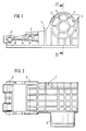
- a water box made of plastic for the radiator of an internal combustion engine for a commercial vehicle, not shown, is shown, to which a finned tube block is attached in a known and therefore not shown manner, which is shown by the water box (1) and one arranged on the opposite side similarly constructed second water tank and is held together like a frame with the help of side parts.
- the side parts overlap the water box (1) with tabs on each end and are connected by bolts to the water box (1) and the second water box, which are inserted through the holes (2) in the water box (1).
- the inflow of the coolant into the water tank and thus to the finned tube block takes place via the connecting piece (3), to which, for example, a hose connection is tightly fastened by means of a pipe clamp in a manner not shown.
- this connecting piece (3) which must be injection molded from plastic, whose wall thickness cannot exceed a certain thickness for manufacturing reasons, to give the necessary rigidity, it is provided to arrange webs (5) projecting inwards into the free cross section from the inner wall (4), which in the embodiment shown show a circular connecting piece (3 ) hit a centrally positioned pipe section (6) with a circular cross-section.
- the webs (5) and the tube (6) are integrally molded onto the connecting piece (3) during the manufacture of the water tank.
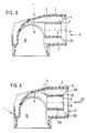
- FIGS. 3 and 4 show that the inner wall (4) of the connecting piece (3) with the outer wall (7) of the pipe section (6) runs approximately parallel.
- the webs (5) likewise run in planes which run through the central axis (8) of the connecting piece (3).
- the connecting piece (3) can therefore be produced by using an appropriate core.
- the two webs at the top in FIGS. 3 and 1 are brought into the area (9) of the connecting piece which is already above the interior (10) of the water tank.
- Fig. 4 shows that this is not absolutely necessary, but that the end of the webs (5) can end before the deflection area (9), as indicated by the dashed lines (11).
- Dash-dotted lines indicate the front edge (30 ') of the webs (5), which are set back somewhat in the flow direction (32) of the coolant relative to the front edge (31) of the connecting piece (3), so that a circular cylindrical surface (29) is created. It is also possible to set the front edge (30 ') back so far that it is flush with the front edge of the pipe section (6).
- connection piece (3) produced in this way is very stable because of its double-walled design.
- the subsequent insertion of a metal sleeve is unnecessary.
- the free cross-section of the connecting piece can be chosen so that it is large enough to allow the required amount of coolant to flow through without pressure losses.
- the stiffening shown by the ribs and the pipe section (6) can also contribute to the inflowing coolant in or out of the water tank as swirl-free as possible.
- Fig. 7 shows a modification of all cross-sectional shapes shown so far for a connecting piece, in that a web and hollow body arrangement arranged asymmetrically to the central axis (8) of the circular cylindrical connecting piece (3) is provided for stiffening.
- the webs (15) run centrally from an axis (16) running parallel to the central axis (8), but which lies eccentrically in the circular cross section of the connecting piece (3).
- a circular cylindrical wall forms a tube piece (17) which concentrically surrounds the axis (16) and from this the webs (15) extend outwards as far as the inner wall (4) of the connecting piece.
- All embodiments can be molded in one piece from plastic. It must of course be ensured that the walls of the webs are arranged parallel to one another and to the inner wall (4) of the connecting piece (3), or better still slightly conically widening outwards, so that the core of the tool used for the production of the plastic water tank is light can be pulled out in the direction of the axis (8).
- the design according to FIG. 4 can be used in a particularly simple manner to use a sealing plug for checking the density of the finished heat exchanger.
- a sealing plug can namely be inserted with a central part into the pipe section (6) and held there by radial spreading on the inner wall (28) of the pipe section (6), while at the same time a part of the sealing plug with a larger diameter on the in the area of Leading edge (31) of the connector plug (3) can be placed tightly on the free annular surface (29).
- all types are unnecessary to insert additional parts, for example in the form of a stiffening sleeve.
- a sealing plug then lies directly against the inner wall of the connecting piece and not against an inserted sleeve, which in turn can be leaky with respect to the connecting piece.
- the exemplary embodiments described for the cooler of the coolant circuit of a commercial vehicle engine can also be used for the connecting pieces of the air boxes of air / air coolers, for example for charge air coolers of diesel engines.
Claims (9)
- Boite de distribution en matière plastique (1) pour échangeurs de chaleur de moteurs à combustion interne, en particulier pour radiateurs de moteur de véhicule utilitaire pourvue d'au moins une tubulure de raccordement (3) destinée à un milieu d'échange de chaleur, pourvue sur sa paroi intérieure (4) d'un élément de rigidification, composé de nervures (5, 15, 5') partant de la paroi intérieure (4) et se projetant vers l'intérieur, caractérisée en ce que les nervures (5, 5', 15) sont réalisées sous forme de parois de guidage d'écoulement, rejoignant une pièce tubulaire (6, 17) creuse et reliées à celle-ci.
- Boite de distribution en matière plastique selon la revendication 1, caractérisée en ce que la pièce tubulaire (6) a une forme cylindrique circulaire.
- Boite de distribution en plastique selon la revendication 2, avec une tubulure de raccordement circulaire, caractérisée en ce que la pièce tubulaire (6) est disposée concentriquement par rapport à l'axe médian (8) de la tubulure de raccordement (3).
- Boite de distribution en plastique selon l'une des revendications 1 à 3, caractérisée en ce que les arêtes avant (30) des nervures (5) sont quelques peu décalées vers l'intérieur par rapport à l'ouverture d'entrée (31) de la tubulure de raccordement (3), au moins dans la zone de la paroi intérieure (4) de la tubulure de raccordement (3), de sorte qu'est constituée une face annulaire (29) faisant le pourtour.
- Boite de distribution en plastique selon l'une des revendications 2 et 4, caractérisée en ce que la pièce tubulaire (17) est disposée excentrée dans la section transversale de la tubulure de raccordement (3).
- Boite de distribution en plastique selon la revendication 1, caractérisée en ce que les nervures (5, 15, 5') sont réalisées d'une seule pièce, venue d'injection.
- Boite de distribution en plastique selon les revendications 1 et 6, caractérisée en ce que les nervures (27) sont réalisées sous forme de nervures de renforcement, réparties régulièrement sur la périphérie intérieure et s'étendant dans la direction de l'écoulement.
- Boite de distribution en plastique selon la revendication 1, caractérisée en ce que les nervures (5, 18, 27) s'étendent radialement par rapport à l'axe médian (8) de la tubulure de raccordement (3).
- Boite de distribution selon la revendication 5, caractérisée en ce que les nervures (15) s'étendent radialement par rapport à un axe médian (16) de la pièce tubulaire excentrique (17).
Applications Claiming Priority (2)
| Application Number | Priority Date | Filing Date | Title |
|---|---|---|---|
| DE9002438U DE9002438U1 (fr) | 1990-03-02 | 1990-03-02 | |
| DE9002438U | 1990-03-02 |
Publications (2)
| Publication Number | Publication Date |
|---|---|
| EP0444423A1 EP0444423A1 (fr) | 1991-09-04 |
| EP0444423B1 true EP0444423B1 (fr) | 1995-05-24 |
Family
ID=6851528
Family Applications (1)
| Application Number | Title | Priority Date | Filing Date |
|---|---|---|---|
| EP91101104A Expired - Lifetime EP0444423B1 (fr) | 1990-03-02 | 1991-01-29 | Boîte de distribution en plastique pour échangeur de chaleur |
Country Status (4)
| Country | Link |
|---|---|
| US (1) | US5107924A (fr) |
| EP (1) | EP0444423B1 (fr) |
| DE (2) | DE9002438U1 (fr) |
| ES (1) | ES2072458T3 (fr) |
Cited By (1)
| Publication number | Priority date | Publication date | Assignee | Title |
|---|---|---|---|---|
| DE102005062365A1 (de) * | 2005-12-23 | 2007-06-28 | Behr Gmbh & Co. Kg | Sammelkasten für einen Wärmeübertrager |
Families Citing this family (22)
| Publication number | Priority date | Publication date | Assignee | Title |
|---|---|---|---|---|
| FR2707915B1 (fr) * | 1993-07-23 | 1995-09-15 | Valeo Thermique Moteur Sa | Boîte en matière plastique moulée avec une tubulure, en particulier pour échangeur de chaleur, et procédé de moulage. |
| US5351751A (en) * | 1993-09-02 | 1994-10-04 | Valeo Engine Cooling, Incorp. | Heat exchanger tank with tie bar |
| WO1997024562A1 (fr) * | 1995-12-28 | 1997-07-10 | H-Tech, Inc. | Element chauffant pour fluides |
| US5649587A (en) * | 1996-02-23 | 1997-07-22 | Mccord Winn Textron, Inc. | Fan shroud and receptacle arrangement |
| US5865244A (en) * | 1997-03-25 | 1999-02-02 | Behr America, Inc. | Plastic header tank matrix and method of making same |
| US5941303A (en) * | 1997-11-04 | 1999-08-24 | Thermal Components | Extruded manifold with multiple passages and cross-counterflow heat exchanger incorporating same |
| US6082446A (en) * | 1998-04-20 | 2000-07-04 | Ahaus Tool And Engineering, Inc. | Sealing method and apparatus for a heat exchanger |
| WO2001098099A1 (fr) | 2000-06-19 | 2001-12-27 | Mccord Winn Textron | Tuyere de ventilateur moulee par soufflage |
| US6543404B2 (en) | 2001-04-04 | 2003-04-08 | Dow Global Technologies, Inc. | Adhesively bonded engine intake manifold assembly |
| EP1255028A3 (fr) * | 2001-05-03 | 2005-05-11 | Kautex Textron GmbH & Co. KG. | Support moulé pas soufflage |
| US20040012125A1 (en) * | 2001-06-19 | 2004-01-22 | Plant William D. | Blow molded fan shroud |
| DE10316755A1 (de) * | 2003-04-10 | 2004-10-28 | Behr Gmbh & Co. Kg | Sammelkasten und Wärmeübertrager |
| DE10316754A1 (de) * | 2003-04-10 | 2004-10-28 | Behr Gmbh & Co. Kg | Sammelkasten, Wärmeübertrager und Verfahren zur Herstellung eines Sammelkastens |
| US7360519B2 (en) * | 2003-07-10 | 2008-04-22 | Dow Global Technologies, Inc. | Engine intake manifold assembly |
| DE10347679A1 (de) * | 2003-10-09 | 2005-05-04 | Behr Gmbh & Co Kg | Wärmeübertrager für ein Kraftfahrzeug, insbesondere Kühlmittel/Luft-Kühler |
| US7198097B2 (en) * | 2003-12-18 | 2007-04-03 | Valeo, Inc. | Angled ribs for heat exchanger tanks |
| US20080271874A1 (en) * | 2007-05-04 | 2008-11-06 | John Gietzen | Thermal energy exchanger |
| US20080066896A1 (en) * | 2006-08-23 | 2008-03-20 | Valeo, Inc. | Heat exchanger with reinforced neck |
| US8720536B2 (en) * | 2009-09-04 | 2014-05-13 | Modine Manufacturing Company | Heat exchanger having flow diverter |
| GB2504547A (en) * | 2012-08-03 | 2014-02-05 | Tube Tech Int Ltd | Parallel tube heat exchanger having a baffle to modify direction and flow rate of an incoming process fluid |
| DE102013209617A1 (de) * | 2013-05-23 | 2014-12-11 | Behr Gmbh & Co. Kg | Abgaswärmeübertrager |
| EP3348947B1 (fr) * | 2017-01-13 | 2020-11-04 | HS Marston Aerospace Limited | Échangeur de chaleur |
Family Cites Families (17)
| Publication number | Priority date | Publication date | Assignee | Title |
|---|---|---|---|---|
| DE7327463U (de) * | 1973-10-25 | Nuessel H | Kunststoffrohr | |
| DE317255C (fr) * | ||||
| DE1257C (de) * | 1877-10-06 | A. BURDAJEWICZ, Klempnermeister, in Polkwitz | Vorrichtung zur Verhinderung des Krippensetzens mit verdeckten Stacheln | |
| US767893A (en) * | 1903-11-11 | 1904-08-16 | Walter Simpson Jewell | Hose-coupling. |
| GB862094A (en) * | 1958-04-26 | 1961-03-01 | Mendip Chemical Engineering Lt | Improvements in or relating to the construction of water boxes for heat exchangers |
| DE2166518C2 (de) * | 1971-07-31 | 1982-10-28 | Wilhelm 8730 Bad Kissingen Hegler | Kunststoffrohr mit einer oder mehreren schraubenförmig gewundenen Trennwänden |
| GB1414473A (en) * | 1972-02-10 | 1975-11-19 | Covrad Ltd | Heat exchangers |
| DE2353362C3 (de) * | 1973-10-25 | 1982-05-13 | Süddeutsche Kühlerfabrik Julius Fr. Behr GmbH & Co KG, 7000 Stuttgart | Wasserkasten für Wärmetauscher |
| FR2302495A1 (fr) * | 1975-02-28 | 1976-09-24 | Rousselin Norbert | Boite de distribution pour echangeur de chaleur |
| FR2499704B1 (fr) * | 1981-02-12 | 1986-08-14 | Valeo | Echangeur de chaleur et son dispositif de boite a eau et vase d'expansion |
| FR2502318B1 (fr) * | 1981-03-23 | 1986-06-06 | Valeo | Dispositif de maintien d'un turbulateur dans un tube d'un echangeur de chaleur |
| DE3428857A1 (de) * | 1984-08-04 | 1986-02-13 | Süddeutsche Kühlerfabrik Julius Fr. Behr GmbH & Co KG, 7000 Stuttgart | Wasser/luft-kuehler fuer wassergekuehlte verbrennungskraftmaschinen |
| JPS61211693A (ja) * | 1985-03-15 | 1986-09-19 | Mitsubishi Heavy Ind Ltd | 復水器 |
| DE3619267A1 (de) * | 1986-06-07 | 1987-12-10 | Sueddeutsche Kuehler Behr | Waermetauscher |
| US4709757A (en) * | 1986-11-24 | 1987-12-01 | Johnson Service Company | Method of injection molding and plastic part formed thereby |
| US4940086A (en) * | 1987-04-16 | 1990-07-10 | Modine Manufacturing Company | Tank for a heat exchanger |
| DE3820623A1 (de) * | 1988-06-17 | 1989-12-21 | Sueddeutsche Kuehler Behr | Wasser/luft-kuehler fuer wassergekuehlte verbrennungskraftmaschinen, insbesondere von nutzfahrzeugen |
-
1990
- 1990-03-02 DE DE9002438U patent/DE9002438U1/de not_active Expired - Lifetime
-
1991
- 1991-01-29 DE DE59105542T patent/DE59105542D1/de not_active Expired - Fee Related
- 1991-01-29 ES ES91101104T patent/ES2072458T3/es not_active Expired - Fee Related
- 1991-01-29 EP EP91101104A patent/EP0444423B1/fr not_active Expired - Lifetime
- 1991-02-19 US US07/656,810 patent/US5107924A/en not_active Expired - Fee Related
Cited By (1)
| Publication number | Priority date | Publication date | Assignee | Title |
|---|---|---|---|---|
| DE102005062365A1 (de) * | 2005-12-23 | 2007-06-28 | Behr Gmbh & Co. Kg | Sammelkasten für einen Wärmeübertrager |
Also Published As
| Publication number | Publication date |
|---|---|
| DE59105542D1 (de) | 1995-06-29 |
| ES2072458T3 (es) | 1995-07-16 |
| US5107924A (en) | 1992-04-28 |
| DE9002438U1 (fr) | 1990-04-12 |
| EP0444423A1 (fr) | 1991-09-04 |
Similar Documents
| Publication | Publication Date | Title |
|---|---|---|
| EP0444423B1 (fr) | Boîte de distribution en plastique pour échangeur de chaleur | |
| DE3311579C2 (de) | Wärmetauscher | |
| DE2644349C2 (de) | Einstückiges Kunststoffrohr mit Längskanälen | |
| EP1435503B1 (fr) | Echangeur de chaleur et ensemble échangeur de chaleur pour véhicules automobiles | |
| EP2044304B1 (fr) | Échangeur de chaleur avec raccord d'accouplement, par exemple refroidisseur d'air de charge, et raccord d'accouplement pour échangeur de chaleur | |
| EP0387678B1 (fr) | Echangeur de chaleur et procédé pour la fixation étanche des éléments d'échange dans une plaque d'extrémité | |
| EP1333219A1 (fr) | Raccord à action rapide | |
| DE3319521C2 (fr) | ||
| DE10014484A1 (de) | Wärmetauscher mit Sammelbehälter | |
| DE4018128A1 (de) | Einrichtung zur kraftstoffverteilung | |
| EP0565813B1 (fr) | Echangeur de chaleur | |
| DE4221913C1 (de) | Ansaugkrümmer für eine Verbrennungskraftmaschine mit einem Zylinderkopf | |
| DE19740471C1 (de) | Modularer Fahrzeugbehälter | |
| DE2930046A1 (de) | Aussengehaeuse fuer ein abgasschalldaempfer fuer brennkraftmaschinen. | |
| EP0180086B1 (fr) | Refroidisseur d'huile | |
| DE3917173C2 (de) | Verfahren zur Herstellung eines Wärmetauscher-Sammlers | |
| EP0305702B1 (fr) | Echangeur de chaleur avec dispositif de tubes à ailettes | |
| DE2756378C2 (de) | Schalldämmend gekapselte Brennkraftmaschine | |
| DE19753390A1 (de) | Stapelförmig angeordneter, schneckenförmiger Krümmer | |
| DE10026706B4 (de) | Klemmenleiste für Einspritzvorrichtungen | |
| DE10041794A1 (de) | Kühleranordnung und Kühler | |
| DE2749205A1 (de) | Roehrenwaermetauscher | |
| DE19746371A1 (de) | Wärmetauscher mit einem Sammelkasten mit zwei aneinander angrenzenden Kammern | |
| DE19744361A1 (de) | Kunststoff-Filter, insbesondere Kraftstoff-Filter | |
| EP0451507B1 (fr) | Echangeur de chaleur |
Legal Events
| Date | Code | Title | Description |
|---|---|---|---|
| PUAI | Public reference made under article 153(3) epc to a published international application that has entered the european phase |
Free format text: ORIGINAL CODE: 0009012 |
|
| AK | Designated contracting states |
Kind code of ref document: A1 Designated state(s): DE ES FR GB IT SE |
|
| 17P | Request for examination filed |
Effective date: 19911023 |
|
| 17Q | First examination report despatched |
Effective date: 19930209 |
|
| ITF | It: translation for a ep patent filed |
Owner name: DE DOMINICIS & MAYER S.R.L. |
|
| GRAA | (expected) grant |
Free format text: ORIGINAL CODE: 0009210 |
|
| AK | Designated contracting states |
Kind code of ref document: B1 Designated state(s): DE ES FR GB IT SE |
|
| REF | Corresponds to: |
Ref document number: 59105542 Country of ref document: DE Date of ref document: 19950629 |
|
| REG | Reference to a national code |
Ref country code: ES Ref legal event code: FG2A Ref document number: 2072458 Country of ref document: ES Kind code of ref document: T3 |
|
| GBT | Gb: translation of ep patent filed (gb section 77(6)(a)/1977) |
Effective date: 19950619 |
|
| ET | Fr: translation filed | ||
| PLBE | No opposition filed within time limit |
Free format text: ORIGINAL CODE: 0009261 |
|
| STAA | Information on the status of an ep patent application or granted ep patent |
Free format text: STATUS: NO OPPOSITION FILED WITHIN TIME LIMIT |
|
| 26N | No opposition filed | ||
| PGFP | Annual fee paid to national office [announced via postgrant information from national office to epo] |
Ref country code: GB Payment date: 19971218 Year of fee payment: 8 |
|
| PGFP | Annual fee paid to national office [announced via postgrant information from national office to epo] |
Ref country code: SE Payment date: 19980123 Year of fee payment: 8 |
|
| PGFP | Annual fee paid to national office [announced via postgrant information from national office to epo] |
Ref country code: FR Payment date: 19990118 Year of fee payment: 9 Ref country code: ES Payment date: 19990118 Year of fee payment: 9 |
|
| PG25 | Lapsed in a contracting state [announced via postgrant information from national office to epo] |
Ref country code: GB Free format text: LAPSE BECAUSE OF NON-PAYMENT OF DUE FEES Effective date: 19990129 |
|
| PG25 | Lapsed in a contracting state [announced via postgrant information from national office to epo] |
Ref country code: SE Free format text: LAPSE BECAUSE OF NON-PAYMENT OF DUE FEES Effective date: 19990130 |
|
| GBPC | Gb: european patent ceased through non-payment of renewal fee |
Effective date: 19990129 |
|
| PG25 | Lapsed in a contracting state [announced via postgrant information from national office to epo] |
Ref country code: ES Free format text: LAPSE BECAUSE OF NON-PAYMENT OF DUE FEES Effective date: 20000131 |
|
| PG25 | Lapsed in a contracting state [announced via postgrant information from national office to epo] |
Ref country code: FR Free format text: LAPSE BECAUSE OF NON-PAYMENT OF DUE FEES Effective date: 20000929 |
|
| REG | Reference to a national code |
Ref country code: FR Ref legal event code: ST |
|
| PGFP | Annual fee paid to national office [announced via postgrant information from national office to epo] |
Ref country code: DE Payment date: 20010212 Year of fee payment: 11 |
|
| REG | Reference to a national code |
Ref country code: ES Ref legal event code: FD2A Effective date: 20010910 |
|
| PG25 | Lapsed in a contracting state [announced via postgrant information from national office to epo] |
Ref country code: DE Free format text: LAPSE BECAUSE OF NON-PAYMENT OF DUE FEES Effective date: 20020801 |
|
| PG25 | Lapsed in a contracting state [announced via postgrant information from national office to epo] |
Ref country code: IT Free format text: LAPSE BECAUSE OF NON-PAYMENT OF DUE FEES Effective date: 20050129 |