EP0444423B1 - Plastic header box for heat exchanger - Google Patents
Plastic header box for heat exchanger Download PDFInfo
- Publication number
- EP0444423B1 EP0444423B1 EP91101104A EP91101104A EP0444423B1 EP 0444423 B1 EP0444423 B1 EP 0444423B1 EP 91101104 A EP91101104 A EP 91101104A EP 91101104 A EP91101104 A EP 91101104A EP 0444423 B1 EP0444423 B1 EP 0444423B1
- Authority
- EP
- European Patent Office
- Prior art keywords
- water tank
- accordance
- plastic water
- piece
- fins
- Prior art date
- Legal status (The legal status is an assumption and is not a legal conclusion. Google has not performed a legal analysis and makes no representation as to the accuracy of the status listed.)
- Expired - Lifetime
Links
Images

Classifications
-
- B—PERFORMING OPERATIONS; TRANSPORTING
- B29—WORKING OF PLASTICS; WORKING OF SUBSTANCES IN A PLASTIC STATE IN GENERAL
- B29C—SHAPING OR JOINING OF PLASTICS; SHAPING OF MATERIAL IN A PLASTIC STATE, NOT OTHERWISE PROVIDED FOR; AFTER-TREATMENT OF THE SHAPED PRODUCTS, e.g. REPAIRING
- B29C45/00—Injection moulding, i.e. forcing the required volume of moulding material through a nozzle into a closed mould; Apparatus therefor
-
- F—MECHANICAL ENGINEERING; LIGHTING; HEATING; WEAPONS; BLASTING
- F28—HEAT EXCHANGE IN GENERAL
- F28F—DETAILS OF HEAT-EXCHANGE AND HEAT-TRANSFER APPARATUS, OF GENERAL APPLICATION
- F28F21/00—Constructions of heat-exchange apparatus characterised by the selection of particular materials
- F28F21/06—Constructions of heat-exchange apparatus characterised by the selection of particular materials of plastics material
- F28F21/067—Details
-
- F—MECHANICAL ENGINEERING; LIGHTING; HEATING; WEAPONS; BLASTING
- F28—HEAT EXCHANGE IN GENERAL
- F28F—DETAILS OF HEAT-EXCHANGE AND HEAT-TRANSFER APPARATUS, OF GENERAL APPLICATION
- F28F9/00—Casings; Header boxes; Auxiliary supports for elements; Auxiliary members within casings
- F28F9/02—Header boxes; End plates
- F28F9/0246—Arrangements for connecting header boxes with flow lines
-
- F—MECHANICAL ENGINEERING; LIGHTING; HEATING; WEAPONS; BLASTING
- F28—HEAT EXCHANGE IN GENERAL
- F28F—DETAILS OF HEAT-EXCHANGE AND HEAT-TRANSFER APPARATUS, OF GENERAL APPLICATION
- F28F2255/00—Heat exchanger elements made of materials having special features or resulting from particular manufacturing processes
- F28F2255/14—Heat exchanger elements made of materials having special features or resulting from particular manufacturing processes molded
- F28F2255/143—Heat exchanger elements made of materials having special features or resulting from particular manufacturing processes molded injection molded
-
- Y—GENERAL TAGGING OF NEW TECHNOLOGICAL DEVELOPMENTS; GENERAL TAGGING OF CROSS-SECTIONAL TECHNOLOGIES SPANNING OVER SEVERAL SECTIONS OF THE IPC; TECHNICAL SUBJECTS COVERED BY FORMER USPC CROSS-REFERENCE ART COLLECTIONS [XRACs] AND DIGESTS
- Y10—TECHNICAL SUBJECTS COVERED BY FORMER USPC
- Y10S—TECHNICAL SUBJECTS COVERED BY FORMER USPC CROSS-REFERENCE ART COLLECTIONS [XRACs] AND DIGESTS
- Y10S165/00—Heat exchange
- Y10S165/906—Reinforcement
Definitions
- the invention relates to a plastic water tank for heat exchangers of internal combustion engines, in particular for coolers of commercial vehicle engines according to the preamble of patent claim 1.
- a water box of this type with a lid into which a connecting piece for a hose connection with locking means provided at one end is inserted into a corresponding opening into which it snaps due to the selected configuration. It has been provided there to provide the fastening part of the connecting piece with stiffening, web-like inner walls in order to secure the snap fit of the plug-in piece in the water tank cover. However, there is no provision for a reinforcement at the point at which the later hose connections must be sealed.
- Plastic water tanks of a similar type are also known, for example, for the coolers of the internal combustion engines of commercial vehicles.
- the through the finned tube block the radiator such
- the amount of coolant flowing to the engine is large, since the performance of the engine to be cooled is also considerable.
- This also requires relatively large water boxes for the coolers.
- the production of the water boxes from plastic makes such large motors require the arrangement of stiffening parts in all the areas of the water box which are subjected to greater forces.
- the coolant connector to which hose connections must be sealed.
- it is known to press metallic support sleeves into the connecting pieces it is known to press metallic support sleeves into the connecting pieces.
- this requires an additional work process and is therefore relatively complex.
- the invention has for its object to provide a plastic water tank of the type mentioned so that the subsequent pressing of metal sleeves is superfluous, but that the connecting piece still have the required rigidity.
- a very simple possibility is to arrange the webs evenly distributed over the inner circumference and to form them in the form of reinforcing ribs which run in the direction of flow.
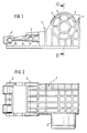
- a water box made of plastic for the radiator of an internal combustion engine for a commercial vehicle, not shown, is shown, to which a finned tube block is attached in a known and therefore not shown manner, which is shown by the water box (1) and one arranged on the opposite side similarly constructed second water tank and is held together like a frame with the help of side parts.
- the side parts overlap the water box (1) with tabs on each end and are connected by bolts to the water box (1) and the second water box, which are inserted through the holes (2) in the water box (1).
- the inflow of the coolant into the water tank and thus to the finned tube block takes place via the connecting piece (3), to which, for example, a hose connection is tightly fastened by means of a pipe clamp in a manner not shown.
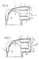
- this connecting piece (3) which must be injection molded from plastic, whose wall thickness cannot exceed a certain thickness for manufacturing reasons, to give the necessary rigidity, it is provided to arrange webs (5) projecting inwards into the free cross section from the inner wall (4), which in the embodiment shown show a circular connecting piece (3 ) hit a centrally positioned pipe section (6) with a circular cross-section.
- the webs (5) and the tube (6) are integrally molded onto the connecting piece (3) during the manufacture of the water tank.
- FIGS. 3 and 4 show that the inner wall (4) of the connecting piece (3) with the outer wall (7) of the pipe section (6) runs approximately parallel.
- the webs (5) likewise run in planes which run through the central axis (8) of the connecting piece (3).
- the connecting piece (3) can therefore be produced by using an appropriate core.
- the two webs at the top in FIGS. 3 and 1 are brought into the area (9) of the connecting piece which is already above the interior (10) of the water tank.
- Fig. 4 shows that this is not absolutely necessary, but that the end of the webs (5) can end before the deflection area (9), as indicated by the dashed lines (11).
- Dash-dotted lines indicate the front edge (30 ') of the webs (5), which are set back somewhat in the flow direction (32) of the coolant relative to the front edge (31) of the connecting piece (3), so that a circular cylindrical surface (29) is created. It is also possible to set the front edge (30 ') back so far that it is flush with the front edge of the pipe section (6).
- connection piece (3) produced in this way is very stable because of its double-walled design.
- the subsequent insertion of a metal sleeve is unnecessary.
- the free cross-section of the connecting piece can be chosen so that it is large enough to allow the required amount of coolant to flow through without pressure losses.
- the stiffening shown by the ribs and the pipe section (6) can also contribute to the inflowing coolant in or out of the water tank as swirl-free as possible.
- Fig. 7 shows a modification of all cross-sectional shapes shown so far for a connecting piece, in that a web and hollow body arrangement arranged asymmetrically to the central axis (8) of the circular cylindrical connecting piece (3) is provided for stiffening.
- the webs (15) run centrally from an axis (16) running parallel to the central axis (8), but which lies eccentrically in the circular cross section of the connecting piece (3).
- a circular cylindrical wall forms a tube piece (17) which concentrically surrounds the axis (16) and from this the webs (15) extend outwards as far as the inner wall (4) of the connecting piece.
- All embodiments can be molded in one piece from plastic. It must of course be ensured that the walls of the webs are arranged parallel to one another and to the inner wall (4) of the connecting piece (3), or better still slightly conically widening outwards, so that the core of the tool used for the production of the plastic water tank is light can be pulled out in the direction of the axis (8).
- the design according to FIG. 4 can be used in a particularly simple manner to use a sealing plug for checking the density of the finished heat exchanger.
- a sealing plug can namely be inserted with a central part into the pipe section (6) and held there by radial spreading on the inner wall (28) of the pipe section (6), while at the same time a part of the sealing plug with a larger diameter on the in the area of Leading edge (31) of the connector plug (3) can be placed tightly on the free annular surface (29).
- all types are unnecessary to insert additional parts, for example in the form of a stiffening sleeve.
- a sealing plug then lies directly against the inner wall of the connecting piece and not against an inserted sleeve, which in turn can be leaky with respect to the connecting piece.
- the exemplary embodiments described for the cooler of the coolant circuit of a commercial vehicle engine can also be used for the connecting pieces of the air boxes of air / air coolers, for example for charge air coolers of diesel engines.
Description
Die Erfindung betrifft einen Kunststoffwasserkasten für Wärmetauscher von Verbrennungskraftmaschinen, insbesondere für Kühler von Nutzfahrzeugmotoren nach dem Oberbegriff des Patentanspruches 1.The invention relates to a plastic water tank for heat exchangers of internal combustion engines, in particular for coolers of commercial vehicle engines according to the preamble of
Aus der FR-A-22 49 299 ist ein Wasserkasten dieser Art mit einem Deckel bekannt, in den ein Anschlußstutzen für einen Schlauchanschluß mit an einem Ende vorgesehenen Rastmitteln in eine korrespondierende Öffnung eingeschoben ist, in die er durch die gewählte Ausgestaltung einschnappt. Man hat dort vorgesehen, den Befestigungsteil des Anschlußstutzens mit versteifenden, stegartigen Innenwänden zu versehen, um den Schnappsitz des einsteckbaren Stutzens in dem Wasserkastendeckel zu sichern. Eine Möglichkeit allerdings eine Verstärkung an der Stelle vorzusehen, an der die späteren Schlauchanschlüsse abgedichtet angebracht werden müssen, ist nicht vorgesehen.From FR-A-22 49 299 a water box of this type with a lid is known, into which a connecting piece for a hose connection with locking means provided at one end is inserted into a corresponding opening into which it snaps due to the selected configuration. It has been provided there to provide the fastening part of the connecting piece with stiffening, web-like inner walls in order to secure the snap fit of the plug-in piece in the water tank cover. However, there is no provision for a reinforcement at the point at which the later hose connections must be sealed.
Kunststoffwasserkästen ähnlicher Art sind beispielsweise auch für die Kühler der Verbrennungskraftmaschinen von Nutzfahrzeugen bekannt. Die durch den Rippenrohrblock der Kühler solcher Motoren strömende Kühlmittelmenge ist, da auch die zu kühlende Leistung der Motoren erheblich ist, groß. Dies bedingt auch relativ große Wasserkästen für die Kühler. Die im Hinblick auf das Gewicht vorgenommene Herstellung der Wasserkästen aus Kunststoff macht bei solchen großen Motoren die Anordnung von Aussteifungsteilen in allen den Bereichen des Wasserkastens erforderlich, die größeren Kräften ausgesetzt sind. Dies gilt neben den Eckbereichen, wo die Seitenteile befestigt werden, auch für den Kühlmittelanschlußstutzen, an dem Schlauchanschlüsse abgedichtet angebracht werden müssen. Es ist aus diesem Grund bekannt, in die Anschlußstutzen metallische Stützhülsen einzupressen. Dies macht aber einen zusätzlichen Arbeitsvorgang erforderlich und ist daher relativ aufwendig.Plastic water tanks of a similar type are also known, for example, for the coolers of the internal combustion engines of commercial vehicles. The through the finned tube block the radiator such The amount of coolant flowing to the engine is large, since the performance of the engine to be cooled is also considerable. This also requires relatively large water boxes for the coolers. With regard to the weight, the production of the water boxes from plastic makes such large motors require the arrangement of stiffening parts in all the areas of the water box which are subjected to greater forces. In addition to the corner areas where the side parts are fastened, this also applies to the coolant connector, to which hose connections must be sealed. For this reason, it is known to press metallic support sleeves into the connecting pieces. However, this requires an additional work process and is therefore relatively complex.
Der Erfindung liegt die Aufgabe zugrunde, einen Kunststoffwasserkasten der eingangs genannten Art so auszubilden, daß das nachträgliche Einpressen von Metallhülsen überflüssig wird, daß trotzdem aber die Anschlußstutzen die erforderliche Steifheit aufweisen.The invention has for its object to provide a plastic water tank of the type mentioned so that the subsequent pressing of metal sleeves is superfluous, but that the connecting piece still have the required rigidity.
Zur Lösung dieser Aufgabe wird bei einem Kunststoffwasserkasten der eingangs genannten Art vorgesehen, daß die Stege als Strömungsleitwände ausgebildet sind, die auf ein hohles Rohrstück stoßen und mit diesem verbunden sind. Diese Ausgestaltung macht es in einfacher Weise möglich, den Anschlußstutzen schon von der Herstellung her entsprechend steif auszubilden. Es wird möglich, den freien Querschnitt auch bei dieser Ausführungsform so auszulegen, daß die erforderliche Kühlmittelmenge zu- oder abfließen kann. Das nachträgliche Anbringen von Zusatzteilen zur Aussteifung des Anschlußstutzens ist überflüssig. Diese Ausgestaltung ergibt auch eine Art doppelwandige Ausbildung, die besonders steif ist. Sie weist den Vorteil auf, daß sie einfach herstellbar ist und daß zur Dichteprüfung des fertigen Kühlers ein Abdichtstopfen einschiebbar und befestigbar ist, der in etwa den gleichen Aufbau hat wie der vorher bei der Herstellung verwendete Kern des Spritzwerkzeuges. Es ist daher auch sehr vorteilhaft nach den Ansprüchen 2 und 3, für kreisrunde Anschlußstutzen das Mittelstück als ein kreiszylinderförmiges Rohrstück auszubilden und konzentrisch im freien Querschnitt anzordnen, wobei die im Anschlußstutzen nach außen weisenden Kanten der Stege nach Anspruch 4 von der Vorderkante des Anschlußstutzens etwas zurückversetzt sind, so daß eine kreiszylinderförmige Dichtfläche gebildet ist, die zur Anlage des Abdichtstopfens für die Dichteprüfung ausgenützt werden kann.To solve this problem it is provided in a plastic water tank of the type mentioned that the webs are designed as flow guide walls that meet a hollow piece of pipe and are connected to this. This configuration makes it possible in a simple manner to design the connecting piece to be correspondingly stiff from the manufacture. It becomes possible to design the free cross section in this embodiment so that the required amount of coolant can flow in or out. The subsequent attachment of additional parts to stiffen the connection piece is unnecessary. This configuration also results in a type of double-walled design that is particularly rigid. It has the advantage that it is easy to manufacture and that a sealing plug can be inserted and fastened for the leak test of the finished cooler, which has approximately the same structure as the core of the injection mold previously used in the production. It is therefore also very advantageous according to
Nach Anspruch 5 kann es auch vorteilhaft sein, insbesondere im Hinblick auf eine notwendige Umlenkung der Strömung durch den Anschlußstutzen, das Mittelstück exzentrisch im Anschlußstutzen anzuordnen.According to
Es gibt verschiedene Möglichkeiten, die einstückig angespritzten Stege auszubilden. Diese Möglichkeiten sind in den weiteren Unteransprüchen aufgeführt.There are various ways of forming the integrally molded webs. These options are listed in the further subclaims.
Eine sehr einfache Möglichkeit ist es, die Stege nach Anspruch 7 gleichmäßig auf dem Innenumfang verteilt anzuordnen und in der Form von Verstärkungsrippen auszubilden, die in der Strömungsrichtung verlaufen.A very simple possibility is to arrange the webs evenly distributed over the inner circumference and to form them in the form of reinforcing ribs which run in the direction of flow.
In allen Fällen ist aus Herstellunggründen darauf zu achten, daß der freie Querschnitt zwischen den Stegen oder dem Mittelstück parallel zueinander verlaufende oder besser leicht konisch nach außen sich erweiternde Wandungen aufweist, damit die Kerne für die Form zur Herstellung des Wasserkastens leicht entfernbar sind.In all cases, for manufacturing reasons, care must be taken to ensure that the free cross-section between the webs or the center piece has walls which run parallel to one another or, preferably, slightly conically widen outwards, so that the cores for the mold for producing the water box can be easily removed.
Die Erfindung ist in der Zeichnung anhand mehrerer Ausführungsformen dargestellt und wird im folgenden erläutert. Es zeigen:
- Fig. 1
- eine schematische Teilfrontansicht des Bereiches des Anschlußstutzens für den Kühlmittelzulauf eines Kunststoffwasserkastens für den Kühler eines Kraftfahrzeugverbrennungsmotors,
- Fig. 2
- die Draufsicht auf den Wasserkasten der Fig. 1,
- Fig. 3
- den Schnitt durch den Wasserkasten der Fig. 1 längs der Schnittlinie III-III,
- Fig. 4
- einen Schnitt ähnlich Fig. 3 bei einer ersten Variante des Anschlußstutzens und
- Fig. 5, 6 und 7
- Frontansichten von Anschlußstutzen ähnlich Fig. 3, jeweils in der Richtung X gesehen, jedoch bei anderer Ausgestaltung der Innenversteifung,
- Fig. 1
- a schematic partial front view of the area the connecting piece for the coolant inlet of a plastic water tank for the cooler of a motor vehicle internal combustion engine,
- Fig. 2
- the top view of the water tank of Fig. 1,
- Fig. 3
- 1 along the section line III-III,
- Fig. 4
- a section similar to FIG. 3 in a first variant of the connecting piece and
- 5, 6 and 7
- 3, each seen in the direction X, but with a different design of the internal stiffening,
In den Fig. 1 bis 3 ist ein aus Kunststoff hergestellter Wasserkasten für den nicht näher gezeigten Kühler eines Verbrennungsmotores für ein Nutzfahrzeug gezeigt, an dem in bekannter und daher nicht gezeigter Weise ein Rippenrohrblock angebracht wird, der von dem gezeigten Wasserkasten (1) und einem auf der Gegenseite angeordneten ähnlich aufgebauten zweiten Wasserkasten und mit Hilfe von Seitenteilen rahmenartig zusammengehalten wird. Die Seitenteile übergreifen den Wasserkasten (1) mit Laschen jeweils stirnseitig und sind durch Bolzen mit den Wasserkästen (1) und dem zweiten Wasserkasten verbunden, die durch die Bohrungen (2) des Wasserkastens (1) hindurchgesteckt sind. Auf der rechten, nicht gezeigten Seite des Wasserkastens befinden sich ähnliche Bohrungen.1 to 3, a water box made of plastic for the radiator of an internal combustion engine for a commercial vehicle, not shown, is shown, to which a finned tube block is attached in a known and therefore not shown manner, which is shown by the water box (1) and one arranged on the opposite side similarly constructed second water tank and is held together like a frame with the help of side parts. The side parts overlap the water box (1) with tabs on each end and are connected by bolts to the water box (1) and the second water box, which are inserted through the holes (2) in the water box (1). On the right side of the water box, not shown, there are similar holes.
Der Zufluß des Kühlmittels in den Wasserkasten und damit zum Rippenrohrblock erfolgt über den Anschlußstutzen (3), an dem in nicht näher dargestellter Weise beispielsweise ein Schlauchanschluß über eine Rohrschelle dicht befestigt wird. Um diesen Anschlußstutzen (3), der aus Kunststoff gespritzt werden muß, dessen Wandstärke aber eine bestimmte Dicke aus Herstellungsgründen nicht überschreiten kann, die notwendige Steifigkeit zu geben, ist vorgesehen, von der Innenwand (4) nach innen in den freien Querschnitt hereinragende Stege (5) anzuordnen, die bei der gezeigten Ausführungsform eines kreisrunden Anschlußstutzens (3) auf ein mittig angeordnetes Rohrstück (6) mit kreisrundem Querschnitt stoßen. Die Stege (5) und das Rohr (6) sind einstückig mit an den Anschlußstutzen (3) bei der Herstellung des Wasserkastens angespritzt. Fig. 3 zeigt, daß die Innenwand (4) des Anschlußstutzens (3) mit der Außenwand (7) des Rohrstückes (6) etwa parallel verläuft. Ebenso verlaufen die Stege (5) in Ebenen, die durch die Mittelachse (8) des Anschlußstutzens (3) verlaufen. Der Anschlußstutzen (3) läßt sich daher durch Verwendung eines entsprechenden Kernes herstellen. Die in der Fig. 3 und 1 oben liegenden beiden Stege sind dabei bis in den Bereich (9) des Anschlußstutzens hereingeführt, der schon über dem Innenraum (10) des Wasserkastens liegt. Fig. 4 zeigt, daß dies nicht unbedingt notwendig ist, sondern daß das Ende der Stege (5) schon vor dem Umlenkbereich (9), wie mit den gestrichelten Linien (11) angedeutet, enden kann. Strichpunktiert ist die Vorderkante (30') der Stege (5) angedeutet, die in der Strömungsrichtung (32) des Kühlmittels gegenüber der Vorderkante (31) des Anschlußstutzens (3) etwas zurückversetzt sind, so daß eine Kreiszylinderfläche (29) entsteht. Es ist auch möglich, die Vorderkante (30') so weit zurückzuversetzen, daß sie mit der Vorderkante des Rohrstückes (6) fluchtet.The inflow of the coolant into the water tank and thus to the finned tube block takes place via the connecting piece (3), to which, for example, a hose connection is tightly fastened by means of a pipe clamp in a manner not shown. Around this connecting piece (3), which must be injection molded from plastic, whose wall thickness cannot exceed a certain thickness for manufacturing reasons, to give the necessary rigidity, it is provided to arrange webs (5) projecting inwards into the free cross section from the inner wall (4), which in the embodiment shown show a circular connecting piece (3 ) hit a centrally positioned pipe section (6) with a circular cross-section. The webs (5) and the tube (6) are integrally molded onto the connecting piece (3) during the manufacture of the water tank. Fig. 3 shows that the inner wall (4) of the connecting piece (3) with the outer wall (7) of the pipe section (6) runs approximately parallel. The webs (5) likewise run in planes which run through the central axis (8) of the connecting piece (3). The connecting piece (3) can therefore be produced by using an appropriate core. The two webs at the top in FIGS. 3 and 1 are brought into the area (9) of the connecting piece which is already above the interior (10) of the water tank. Fig. 4 shows that this is not absolutely necessary, but that the end of the webs (5) can end before the deflection area (9), as indicated by the dashed lines (11). Dash-dotted lines indicate the front edge (30 ') of the webs (5), which are set back somewhat in the flow direction (32) of the coolant relative to the front edge (31) of the connecting piece (3), so that a circular cylindrical surface (29) is created. It is also possible to set the front edge (30 ') back so far that it is flush with the front edge of the pipe section (6).
Aus den Fig. 1 und 3 wird deutlich, daß der auf diese Weise hergestellte Anschlußstutzen (3) wegen seiner doppelwandigen Ausbildung sehr stabil ist. Das nachträgliche Einsetzen einer Metallhülse wird überflüssig. Der freie Querschnitt des Anschlußstutzens kann so gewählt werden, daß er groß genug ist, um die erforderliche Kühlmittelmenge ohne Druckverluste durchströmen zu lassen. Die gezeigte Aussteifung durch die Rippen und das Rohrstück (6) kann auch mit dazu beitragen, das zuströmende Kühlmittel möglichst wirbelfrei in in den Wasserkasten herein- oder wieder aus dem herauszuführen.1 and 3 it is clear that the connection piece (3) produced in this way is very stable because of its double-walled design. The subsequent insertion of a metal sleeve is unnecessary. The free cross-section of the connecting piece can be chosen so that it is large enough to allow the required amount of coolant to flow through without pressure losses. The stiffening shown by the ribs and the pipe section (6) can also contribute to the inflowing coolant in or out of the water tank as swirl-free as possible.
Die Fig. 5 und 6 zeigen Querschnittsformen der Aussteifung des Anschlußstutzens (3), die im Längsschnitt etwa den in den Fig. 3 und 4 gezeigten Schnittformen entsprechen können. Fig. 5 zeigt im Unterschied zu der Darstellung nach Fig. 1 aber kein kreiszylinderförmiges Rohrstück, sondern ein Rohrstück (6a), das als ein in der Form eines gleichmäßigen Sechseckes ausgebildetes Polygon ausgebildet ist. Fig. 6 dagegen zeigt eine Ausführungsform, bei der die Stege (5', 5'') nicht radial wie die Stege (5) der Fig. 1 bis 5 verlaufen, sondern bei der nur die Stege (5'') radial zum Zentrum der Achse (8) hin verlaufen, die Stege (5') aber jeweils im Abstand zu einer Ebene (12) verlaufen, die senkrecht auf einer durch die Mittelachse (8) verlaufenden Ebene (13) steht, in der die beiden Stege (5') liegen. Die somit außermittig liegenden beiden Stege (5') bilden mit Querstegen (14) ein im Querschnitt quadratisches Mittelstück, das quaderartig ausgebildet ist und dessen Mittelachse die Achse (8) ist.5 and 6 show cross-sectional shapes of the stiffening of the connecting piece (3), which may correspond approximately in longitudinal section to the sectional shapes shown in FIGS. 3 and 4. In contrast to the representation according to FIG. 1, FIG. 5 does not show a tubular piece of circular cylinder, but a piece of pipe (6a) which is designed as a polygon in the form of a uniform hexagon. 6, on the other hand, shows an embodiment in which the webs (5 ', 5' ') do not run radially like the webs (5) of FIGS. 1 to 5, but in which only the webs (5' ') run radially to the center of the axis (8), but the webs (5 ') each run at a distance from a plane (12) which is perpendicular to a plane (13) running through the central axis (8), in which the two webs (5 ') lie. The two webs (5 '), which are thus off-center, form with transverse webs (14) a central piece with a square cross section, which is cuboid in shape and whose central axis is the axis (8).
Fig. 7 zeigt eine Abwandlung aller bisher gezeigten Querschnittsformen für einen Anschlußstutzen insofern, als hier eine zur Mittelachse (8) des kreiszylinderförmigen Anschlußstutzens (3) asymmetrisch angeordnete Steg- und Hohlkörperanordnung zur Aussteifung vorgesehen ist. Hier verlaufen die Stege (15) zentral von einer parallel zur Mittelachse (8) verlaufenden Achse (16) aus, die aber exzentrisch im Kreisquerschnitt des Anschlußstutzens (3) liegt. Eine kreiszylinderförmige Wandung bildet ein Rohrstück (17), das konzentrisch die Achse (16) umgibt und von dieser aus erstrecken sich in der vorher geschilderten Weise die Stege (15) nach außen bis zur Innenwandung (4) des Anschlußstutzens. Solche Aussteifungen bieten sich beispielsweise an, um die Kühlmittelströmung im Anschlußstutzen mengenmäßig aufzuteilen, um beispielsweise, bei entsprechender Anordnung der exzentrischen Achse (16), den größeren Teil der Kühlmittel-Strömung am Bereich (9) der Umlenkwandung umzulenken, den durch das Rohrstück (17) durchgeführten Teil jedoch erst später der umgelenkten Strömung zuzumischen.Fig. 7 shows a modification of all cross-sectional shapes shown so far for a connecting piece, in that a web and hollow body arrangement arranged asymmetrically to the central axis (8) of the circular cylindrical connecting piece (3) is provided for stiffening. Here the webs (15) run centrally from an axis (16) running parallel to the central axis (8), but which lies eccentrically in the circular cross section of the connecting piece (3). A circular cylindrical wall forms a tube piece (17) which concentrically surrounds the axis (16) and from this the webs (15) extend outwards as far as the inner wall (4) of the connecting piece. Such stiffeners are suitable, for example, in order to divide the quantity of coolant flow in the connecting piece in order, for example, with a corresponding arrangement of the eccentric axis (16) To divert a larger part of the coolant flow at the area (9) of the deflection wall, but to mix the part passed through the pipe section (17) into the deflected flow only later.
Alle Ausführungsformen lassen sich einstückig aus Kunststoff formen. Es ist natürlich darauf zu achten, daß die Wände der Stege untereinander und zu der Innenwand (4) des Anschlußstutzens (3) parallel oder besser noch leicht konisch sich nach außen erweiternd angeordnet sind, damit der für die Herstellung des Kunststoffwasserkastens verwendete Kern des Werkzeuges leicht in Richtung der Achse (8) herausgezogen werden kann.All embodiments can be molded in one piece from plastic. It must of course be ensured that the walls of the webs are arranged parallel to one another and to the inner wall (4) of the connecting piece (3), or better still slightly conically widening outwards, so that the core of the tool used for the production of the plastic water tank is light can be pulled out in the direction of the axis (8).
Erwähnt werden soll noch, daß beispielsweise die Bauart nach Fig. 4 in besonders einfacher Weise dazu ausgenützt werden kann, um zur Dichteprüfung des fertigen Wärmetauschers einen Dichtstopfen einzusetzen. Ein solcher Dichtstopfen nämlich kann mit einem zentralen Teil in das Rohrstück (6) eingeschoben und dort durch radiales Aufspreizen an der Innenwandung (28) des Rohrstückes (6) dicht gehalten werden, wobei gleichzeitig ein Teil des Dichtstopfens mit größerem Durchmesser an der im Bereich der Eintrittskante (31) des Anschlußstopfens (3) an frei bleibenden Ringfläche (29) dicht angesetzt werden kann. Bei allen Bauarten ist trotz hoher Stabilität des Anschlußstutzens ein nachträgliches Einsetzen von zusätzlichen Teilen, beispielsweise in der Form einer Aussteifungshülse, unnötig. Vorteilhaft ist auch dabei, daß ein Dichtstopfen dann unmittelbar dicht an der Innenwand des Anschlußstutzens und nicht an einer eingesetzten Hülse anliegt, die ihrerseits wiederum gegenüber dem Anschlußstutzen undicht sein kann.It should also be mentioned that, for example, the design according to FIG. 4 can be used in a particularly simple manner to use a sealing plug for checking the density of the finished heat exchanger. Such a sealing plug can namely be inserted with a central part into the pipe section (6) and held there by radial spreading on the inner wall (28) of the pipe section (6), while at the same time a part of the sealing plug with a larger diameter on the in the area of Leading edge (31) of the connector plug (3) can be placed tightly on the free annular surface (29). In spite of the high stability of the connecting piece, all types are unnecessary to insert additional parts, for example in the form of a stiffening sleeve. It is also advantageous that a sealing plug then lies directly against the inner wall of the connecting piece and not against an inserted sleeve, which in turn can be leaky with respect to the connecting piece.
Die für den Kühler des Kühlmittelkreislaufes eines Nutzfahrzeugmotores beschriebenen Ausführungsbeispiele lassen sich auch für die Anschlußstutzen der Luftkästen von Luft/Luft-Kühlern verwenden, zum Beispiel für Ladeluftkühler von Dieselmotoren.The exemplary embodiments described for the cooler of the coolant circuit of a commercial vehicle engine can also be used for the connecting pieces of the air boxes of air / air coolers, for example for charge air coolers of diesel engines.
Claims (9)
- A plastic water tank (1) for a heat exchanger in an internal combustion engine, in particular for a radiator in a service vehicle, fitted with at leat one adaptor (3) for a heat exchange medium, the internal wall (4) of which is reinforced by means of fins (5, 15, 5') protruding outward and inward from the internal wall (4), characterised in that the fins (5, 15, 5') are designed as flow guide walls which abut against a hollow piece of pipe (6, 17) to which they are connected.
- A plastic water tank in accordance with claim 1, characterised in that the piece of pipe (6) is designed in the form of a circular cylinder.
- A plastic water tank in accordance with claim 2 with a circular adaptor, characterised in that the piece of pipe (6) is positioned concentrically in relation to the centre axis (8) of the adaptor (3).
- A plastic water tank in accordance with one of claims 1 to 3, characterised in that at least in the area of the internal wall (4) of the adaptor (3) the front edges (30) of the fins (5) are set slightly back from the inlet opening (31) of the adaptor (3) thus creating a ring surface (29) around it.
- A plastic water tank in accordance with one of claims 2 and 4, characterised in that the piece of pipe (17) is positioned eccentrically in the cross section of the adaptor (3).
- A plastic water tank in accordance with claim 1, characterised in that the fins (5, 15, 5') are injection moulded in one piece.
- A plastic water tank in accordance with claims 1 and 6, characterised in that the fins (27) are designed as reinforcing ribs distributed equally around the internal circumference which run in the direction of flow.
- A plastic water tank in accordance with claim 1, characterised in that the fins (5, 15, 5') run radially in relation to the centre axis (8) of the adaptor (3).
- A plastic water tank in accordance with claim 5, characterised in that the fins (15) run radially in relation to a centre axis (16) of the eccentric piece of pipe (17).
Applications Claiming Priority (2)
| Application Number | Priority Date | Filing Date | Title |
|---|---|---|---|
| DE9002438U | 1990-03-02 | ||
| DE9002438U DE9002438U1 (en) | 1990-03-02 | 1990-03-02 |
Publications (2)
| Publication Number | Publication Date |
|---|---|
| EP0444423A1 EP0444423A1 (en) | 1991-09-04 |
| EP0444423B1 true EP0444423B1 (en) | 1995-05-24 |
Family
ID=6851528
Family Applications (1)
| Application Number | Title | Priority Date | Filing Date |
|---|---|---|---|
| EP91101104A Expired - Lifetime EP0444423B1 (en) | 1990-03-02 | 1991-01-29 | Plastic header box for heat exchanger |
Country Status (4)
| Country | Link |
|---|---|
| US (1) | US5107924A (en) |
| EP (1) | EP0444423B1 (en) |
| DE (2) | DE9002438U1 (en) |
| ES (1) | ES2072458T3 (en) |
Cited By (1)
| Publication number | Priority date | Publication date | Assignee | Title |
|---|---|---|---|---|
| DE102005062365A1 (en) * | 2005-12-23 | 2007-06-28 | Behr Gmbh & Co. Kg | Collector box for heat transmitter has at least one curved wall sector merging with cylindrical wall region to divert fluid flow through about 90 degrees |
Families Citing this family (22)
| Publication number | Priority date | Publication date | Assignee | Title |
|---|---|---|---|---|
| FR2707915B1 (en) * | 1993-07-23 | 1995-09-15 | Valeo Thermique Moteur Sa | Plastic molded box with tubing, in particular for heat exchanger, and molding process. |
| US5351751A (en) * | 1993-09-02 | 1994-10-04 | Valeo Engine Cooling, Incorp. | Heat exchanger tank with tie bar |
| WO1997024562A1 (en) * | 1995-12-28 | 1997-07-10 | H-Tech, Inc. | Heater for fluids |
| US5649587A (en) * | 1996-02-23 | 1997-07-22 | Mccord Winn Textron, Inc. | Fan shroud and receptacle arrangement |
| US5865244A (en) * | 1997-03-25 | 1999-02-02 | Behr America, Inc. | Plastic header tank matrix and method of making same |
| US5941303A (en) * | 1997-11-04 | 1999-08-24 | Thermal Components | Extruded manifold with multiple passages and cross-counterflow heat exchanger incorporating same |
| US6082446A (en) * | 1998-04-20 | 2000-07-04 | Ahaus Tool And Engineering, Inc. | Sealing method and apparatus for a heat exchanger |
| JP2003535764A (en) | 2000-06-19 | 2003-12-02 | マコード ウィン テクストロン インコーポレイテッド | Blow molding fan shroud |
| US6543404B2 (en) * | 2001-04-04 | 2003-04-08 | Dow Global Technologies, Inc. | Adhesively bonded engine intake manifold assembly |
| EP1255028A3 (en) * | 2001-05-03 | 2005-05-11 | Kautex Textron GmbH & Co. KG. | Blow molded support |
| US20040012125A1 (en) * | 2001-06-19 | 2004-01-22 | Plant William D. | Blow molded fan shroud |
| DE10316754A1 (en) * | 2003-04-10 | 2004-10-28 | Behr Gmbh & Co. Kg | Collecting box, heat exchanger and method for producing a collecting box |
| DE10316755A1 (en) * | 2003-04-10 | 2004-10-28 | Behr Gmbh & Co. Kg | Collecting box and heat exchanger |
| US7360519B2 (en) * | 2003-07-10 | 2008-04-22 | Dow Global Technologies, Inc. | Engine intake manifold assembly |
| DE10347679A1 (en) * | 2003-10-09 | 2005-05-04 | Behr Gmbh & Co Kg | Heat exchanger for a motor vehicle, in particular coolant / air cooler |
| US7198097B2 (en) * | 2003-12-18 | 2007-04-03 | Valeo, Inc. | Angled ribs for heat exchanger tanks |
| US20080271874A1 (en) * | 2007-05-04 | 2008-11-06 | John Gietzen | Thermal energy exchanger |
| US20080066896A1 (en) * | 2006-08-23 | 2008-03-20 | Valeo, Inc. | Heat exchanger with reinforced neck |
| US8720536B2 (en) * | 2009-09-04 | 2014-05-13 | Modine Manufacturing Company | Heat exchanger having flow diverter |
| GB2504547A (en) * | 2012-08-03 | 2014-02-05 | Tube Tech Int Ltd | Parallel tube heat exchanger having a baffle to modify direction and flow rate of an incoming process fluid |
| DE102013209617A1 (en) * | 2013-05-23 | 2014-12-11 | Behr Gmbh & Co. Kg | Exhaust gas heat exchanger |
| EP3348947B1 (en) * | 2017-01-13 | 2020-11-04 | HS Marston Aerospace Limited | Heat exchanger |
Family Cites Families (17)
| Publication number | Priority date | Publication date | Assignee | Title |
|---|---|---|---|---|
| DE7327463U (en) * | 1973-10-25 | Nuessel H | Plastic pipe | |
| DE317255C (en) * | ||||
| DE1257C (en) * | 1877-10-06 | A. BURDAJEWICZ, Klempnermeister, in Polkwitz | Device to prevent the nativity scene with hidden spikes | |
| US767893A (en) * | 1903-11-11 | 1904-08-16 | Walter Simpson Jewell | Hose-coupling. |
| GB862094A (en) * | 1958-04-26 | 1961-03-01 | Mendip Chemical Engineering Lt | Improvements in or relating to the construction of water boxes for heat exchangers |
| DE2166518C2 (en) * | 1971-07-31 | 1982-10-28 | Wilhelm 8730 Bad Kissingen Hegler | Plastic pipe with one or more helically wound partitions |
| GB1414473A (en) * | 1972-02-10 | 1975-11-19 | Covrad Ltd | Heat exchangers |
| DE2353362C3 (en) * | 1973-10-25 | 1982-05-13 | Süddeutsche Kühlerfabrik Julius Fr. Behr GmbH & Co KG, 7000 Stuttgart | Water box for heat exchangers |
| FR2302495A1 (en) * | 1975-02-28 | 1976-09-24 | Rousselin Norbert | Thermoset mouldings for heat exchanger caps - to avoid fabrication and machining costs |
| FR2499704B1 (en) * | 1981-02-12 | 1986-08-14 | Valeo | HEAT EXCHANGER AND ITS WATER BOX DEVICE AND EXPANSION VESSEL |
| FR2502318B1 (en) * | 1981-03-23 | 1986-06-06 | Valeo | DEVICE FOR HOLDING A TURBULATOR IN A TUBE OF A HEAT EXCHANGER |
| DE3428857A1 (en) * | 1984-08-04 | 1986-02-13 | Süddeutsche Kühlerfabrik Julius Fr. Behr GmbH & Co KG, 7000 Stuttgart | WATER / AIR COOLER FOR WATER-COOLED COMBUSTION ENGINES |
| JPS61211693A (en) * | 1985-03-15 | 1986-09-19 | Mitsubishi Heavy Ind Ltd | Condenser |
| DE3619267A1 (en) * | 1986-06-07 | 1987-12-10 | Sueddeutsche Kuehler Behr | Heat exchanger |
| US4709757A (en) * | 1986-11-24 | 1987-12-01 | Johnson Service Company | Method of injection molding and plastic part formed thereby |
| US4940086A (en) * | 1987-04-16 | 1990-07-10 | Modine Manufacturing Company | Tank for a heat exchanger |
| DE3820623A1 (en) * | 1988-06-17 | 1989-12-21 | Sueddeutsche Kuehler Behr | WATER / AIR COOLER FOR WATER-COOLED COMBUSTION ENGINES, ESPECIALLY COMMERCIAL VEHICLES |
-
1990
- 1990-03-02 DE DE9002438U patent/DE9002438U1/de not_active Expired - Lifetime
-
1991
- 1991-01-29 DE DE59105542T patent/DE59105542D1/en not_active Expired - Fee Related
- 1991-01-29 EP EP91101104A patent/EP0444423B1/en not_active Expired - Lifetime
- 1991-01-29 ES ES91101104T patent/ES2072458T3/en not_active Expired - Fee Related
- 1991-02-19 US US07/656,810 patent/US5107924A/en not_active Expired - Fee Related
Cited By (1)
| Publication number | Priority date | Publication date | Assignee | Title |
|---|---|---|---|---|
| DE102005062365A1 (en) * | 2005-12-23 | 2007-06-28 | Behr Gmbh & Co. Kg | Collector box for heat transmitter has at least one curved wall sector merging with cylindrical wall region to divert fluid flow through about 90 degrees |
Also Published As
| Publication number | Publication date |
|---|---|
| US5107924A (en) | 1992-04-28 |
| ES2072458T3 (en) | 1995-07-16 |
| EP0444423A1 (en) | 1991-09-04 |
| DE9002438U1 (en) | 1990-04-12 |
| DE59105542D1 (en) | 1995-06-29 |
Similar Documents
| Publication | Publication Date | Title |
|---|---|---|
| EP0444423B1 (en) | Plastic header box for heat exchanger | |
| DE3311579C2 (en) | Heat exchanger | |
| DE2644349C2 (en) | One-piece plastic tube with longitudinal channels | |
| EP1435503B1 (en) | Heat exchanger and heat exchanger assembly for vehicles | |
| EP2044304B1 (en) | Heat exchanger with coupling connection, for example charge air cooler, and coupling connection for heat exchanger | |
| EP0387678B1 (en) | Heat exchanger and process for the watertight fixation of heat exchange elements to an end plate | |
| EP1333219A1 (en) | Quick acting coupling | |
| DE3319521C2 (en) | ||
| DE10014484A1 (en) | Heat exchanger with collection container has collection container wall with transverse connecting regions, each connected to pipe, wall with differently spaced strengthening ribs | |
| DE4018128A1 (en) | FUEL DISTRIBUTION DEVICE | |
| EP0565813B1 (en) | Heat-exchanger | |
| DE4221913C1 (en) | Intake manifold for an internal combustion engine with a cylinder head | |
| DE19740471C1 (en) | Modular motor vehicle fuel tank | |
| DE2930046A1 (en) | EXTERNAL HOUSING FOR AN EXHAUST SILENCER FOR INTERNAL COMBUSTION ENGINES. | |
| EP0180086B1 (en) | Oil cooler | |
| DE3917173C2 (en) | Process for the production of a heat exchanger collector | |
| EP0305702B1 (en) | Heat exchanger with a finned tube arrangement | |
| DE102008006153B3 (en) | Air intake duct system with integrated intercooler | |
| DE2756378C2 (en) | Sound-absorbing encapsulated internal combustion engine | |
| DE19753390A1 (en) | Tuned air intake manifold for IC engine | |
| DE10026706B4 (en) | Terminal block for injectors | |
| DE10041794A1 (en) | Cooling assembly, with a number of chill units, has a connection near the end of the leading and/or final flat tube for the inflow/outflow channels, to give a more compact structure | |
| DE2749205A1 (en) | Heat exchanger for motor vehicle cooling - has injection moulded header tank bottom with embedded tube ends | |
| DE19746371A1 (en) | Heat exchanger with twin=chamber collection box | |
| EP0451507B1 (en) | Heat-exchanger |
Legal Events
| Date | Code | Title | Description |
|---|---|---|---|
| PUAI | Public reference made under article 153(3) epc to a published international application that has entered the european phase |
Free format text: ORIGINAL CODE: 0009012 |
|
| AK | Designated contracting states |
Kind code of ref document: A1 Designated state(s): DE ES FR GB IT SE |
|
| 17P | Request for examination filed |
Effective date: 19911023 |
|
| 17Q | First examination report despatched |
Effective date: 19930209 |
|
| ITF | It: translation for a ep patent filed |
Owner name: DE DOMINICIS & MAYER S.R.L. |
|
| GRAA | (expected) grant |
Free format text: ORIGINAL CODE: 0009210 |
|
| AK | Designated contracting states |
Kind code of ref document: B1 Designated state(s): DE ES FR GB IT SE |
|
| REF | Corresponds to: |
Ref document number: 59105542 Country of ref document: DE Date of ref document: 19950629 |
|
| REG | Reference to a national code |
Ref country code: ES Ref legal event code: FG2A Ref document number: 2072458 Country of ref document: ES Kind code of ref document: T3 |
|
| GBT | Gb: translation of ep patent filed (gb section 77(6)(a)/1977) |
Effective date: 19950619 |
|
| ET | Fr: translation filed | ||
| PLBE | No opposition filed within time limit |
Free format text: ORIGINAL CODE: 0009261 |
|
| STAA | Information on the status of an ep patent application or granted ep patent |
Free format text: STATUS: NO OPPOSITION FILED WITHIN TIME LIMIT |
|
| 26N | No opposition filed | ||
| PGFP | Annual fee paid to national office [announced via postgrant information from national office to epo] |
Ref country code: GB Payment date: 19971218 Year of fee payment: 8 |
|
| PGFP | Annual fee paid to national office [announced via postgrant information from national office to epo] |
Ref country code: SE Payment date: 19980123 Year of fee payment: 8 |
|
| PGFP | Annual fee paid to national office [announced via postgrant information from national office to epo] |
Ref country code: FR Payment date: 19990118 Year of fee payment: 9 Ref country code: ES Payment date: 19990118 Year of fee payment: 9 |
|
| PG25 | Lapsed in a contracting state [announced via postgrant information from national office to epo] |
Ref country code: GB Free format text: LAPSE BECAUSE OF NON-PAYMENT OF DUE FEES Effective date: 19990129 |
|
| PG25 | Lapsed in a contracting state [announced via postgrant information from national office to epo] |
Ref country code: SE Free format text: LAPSE BECAUSE OF NON-PAYMENT OF DUE FEES Effective date: 19990130 |
|
| GBPC | Gb: european patent ceased through non-payment of renewal fee |
Effective date: 19990129 |
|
| PG25 | Lapsed in a contracting state [announced via postgrant information from national office to epo] |
Ref country code: ES Free format text: LAPSE BECAUSE OF NON-PAYMENT OF DUE FEES Effective date: 20000131 |
|
| PG25 | Lapsed in a contracting state [announced via postgrant information from national office to epo] |
Ref country code: FR Free format text: LAPSE BECAUSE OF NON-PAYMENT OF DUE FEES Effective date: 20000929 |
|
| REG | Reference to a national code |
Ref country code: FR Ref legal event code: ST |
|
| PGFP | Annual fee paid to national office [announced via postgrant information from national office to epo] |
Ref country code: DE Payment date: 20010212 Year of fee payment: 11 |
|
| REG | Reference to a national code |
Ref country code: ES Ref legal event code: FD2A Effective date: 20010910 |
|
| PG25 | Lapsed in a contracting state [announced via postgrant information from national office to epo] |
Ref country code: DE Free format text: LAPSE BECAUSE OF NON-PAYMENT OF DUE FEES Effective date: 20020801 |
|
| PG25 | Lapsed in a contracting state [announced via postgrant information from national office to epo] |
Ref country code: IT Free format text: LAPSE BECAUSE OF NON-PAYMENT OF DUE FEES Effective date: 20050129 |