EP0387678B1 - Echangeur de chaleur et procédé pour la fixation étanche des éléments d'échange dans une plaque d'extrémité - Google Patents
Echangeur de chaleur et procédé pour la fixation étanche des éléments d'échange dans une plaque d'extrémité Download PDFInfo
- Publication number
- EP0387678B1 EP0387678B1 EP90104324A EP90104324A EP0387678B1 EP 0387678 B1 EP0387678 B1 EP 0387678B1 EP 90104324 A EP90104324 A EP 90104324A EP 90104324 A EP90104324 A EP 90104324A EP 0387678 B1 EP0387678 B1 EP 0387678B1
- Authority
- EP
- European Patent Office
- Prior art keywords
- tube ends
- tubes
- heat exchanger
- diameter
- widening
- Prior art date
- Legal status (The legal status is an assumption and is not a legal conclusion. Google has not performed a legal analysis and makes no representation as to the accuracy of the status listed.)
- Expired - Lifetime
Links
- 238000000034 method Methods 0.000 title claims abstract description 29
- 238000007789 sealing Methods 0.000 claims description 31
- 238000003780 insertion Methods 0.000 claims description 9
- 230000037431 insertion Effects 0.000 claims description 9
- 238000003825 pressing Methods 0.000 abstract description 11
- 238000004519 manufacturing process Methods 0.000 description 7
- 230000007704 transition Effects 0.000 description 5
- 239000002826 coolant Substances 0.000 description 2
- 239000003292 glue Substances 0.000 description 2
- 239000000463 material Substances 0.000 description 2
- 239000002184 metal Substances 0.000 description 2
- 238000000465 moulding Methods 0.000 description 2
- 230000002093 peripheral effect Effects 0.000 description 2
- 229910000679 solder Inorganic materials 0.000 description 2
- XLYOFNOQVPJJNP-UHFFFAOYSA-N water Substances O XLYOFNOQVPJJNP-UHFFFAOYSA-N 0.000 description 2
- QNRATNLHPGXHMA-XZHTYLCXSA-N (r)-(6-ethoxyquinolin-4-yl)-[(2s,4s,5r)-5-ethyl-1-azabicyclo[2.2.2]octan-2-yl]methanol;hydrochloride Chemical compound Cl.C([C@H]([C@H](C1)CC)C2)CN1[C@@H]2[C@H](O)C1=CC=NC2=CC=C(OCC)C=C21 QNRATNLHPGXHMA-XZHTYLCXSA-N 0.000 description 1
- 241000722921 Tulipa gesneriana Species 0.000 description 1
- 230000006978 adaptation Effects 0.000 description 1
- 238000004026 adhesive bonding Methods 0.000 description 1
- 238000005452 bending Methods 0.000 description 1
- 230000015572 biosynthetic process Effects 0.000 description 1
- 238000001816 cooling Methods 0.000 description 1
- 230000001627 detrimental effect Effects 0.000 description 1
- 229920001971 elastomer Polymers 0.000 description 1
- 239000000806 elastomer Substances 0.000 description 1
- 238000001746 injection moulding Methods 0.000 description 1
- 239000007788 liquid Substances 0.000 description 1
- 230000036316 preload Effects 0.000 description 1
- 230000000717 retained effect Effects 0.000 description 1
- 239000000565 sealant Substances 0.000 description 1
- 230000035939 shock Effects 0.000 description 1
- 238000005507 spraying Methods 0.000 description 1
- 230000003068 static effect Effects 0.000 description 1
- 238000005482 strain hardening Methods 0.000 description 1
- 238000003466 welding Methods 0.000 description 1
Images


Classifications
-
- F—MECHANICAL ENGINEERING; LIGHTING; HEATING; WEAPONS; BLASTING
- F28—HEAT EXCHANGE IN GENERAL
- F28F—DETAILS OF HEAT-EXCHANGE AND HEAT-TRANSFER APPARATUS, OF GENERAL APPLICATION
- F28F9/00—Casings; Header boxes; Auxiliary supports for elements; Auxiliary members within casings
- F28F9/02—Header boxes; End plates
- F28F9/04—Arrangements for sealing elements into header boxes or end plates
- F28F9/16—Arrangements for sealing elements into header boxes or end plates by permanent joints, e.g. by rolling
- F28F9/165—Arrangements for sealing elements into header boxes or end plates by permanent joints, e.g. by rolling by using additional preformed parts, e.g. sleeves, gaskets
-
- F—MECHANICAL ENGINEERING; LIGHTING; HEATING; WEAPONS; BLASTING
- F28—HEAT EXCHANGE IN GENERAL
- F28F—DETAILS OF HEAT-EXCHANGE AND HEAT-TRANSFER APPARATUS, OF GENERAL APPLICATION
- F28F11/00—Arrangements for sealing leaky tubes and conduits
-
- B—PERFORMING OPERATIONS; TRANSPORTING
- B21—MECHANICAL METAL-WORKING WITHOUT ESSENTIALLY REMOVING MATERIAL; PUNCHING METAL
- B21D—WORKING OR PROCESSING OF SHEET METAL OR METAL TUBES, RODS OR PROFILES WITHOUT ESSENTIALLY REMOVING MATERIAL; PUNCHING METAL
- B21D39/00—Application of procedures in order to connect objects or parts, e.g. coating with sheet metal otherwise than by plating; Tube expanders
- B21D39/08—Tube expanders
- B21D39/20—Tube expanders with mandrels, e.g. expandable
-
- B—PERFORMING OPERATIONS; TRANSPORTING
- B21—MECHANICAL METAL-WORKING WITHOUT ESSENTIALLY REMOVING MATERIAL; PUNCHING METAL
- B21D—WORKING OR PROCESSING OF SHEET METAL OR METAL TUBES, RODS OR PROFILES WITHOUT ESSENTIALLY REMOVING MATERIAL; PUNCHING METAL
- B21D53/00—Making other particular articles
- B21D53/02—Making other particular articles heat exchangers or parts thereof, e.g. radiators, condensers fins, headers
- B21D53/08—Making other particular articles heat exchangers or parts thereof, e.g. radiators, condensers fins, headers of both metal tubes and sheet metal
- B21D53/085—Making other particular articles heat exchangers or parts thereof, e.g. radiators, condensers fins, headers of both metal tubes and sheet metal with fins places on zig-zag tubes or parallel tubes
-
- F—MECHANICAL ENGINEERING; LIGHTING; HEATING; WEAPONS; BLASTING
- F28—HEAT EXCHANGE IN GENERAL
- F28D—HEAT-EXCHANGE APPARATUS, NOT PROVIDED FOR IN ANOTHER SUBCLASS, IN WHICH THE HEAT-EXCHANGE MEDIA DO NOT COME INTO DIRECT CONTACT
- F28D1/00—Heat-exchange apparatus having stationary conduit assemblies for one heat-exchange medium only, the media being in contact with different sides of the conduit wall, in which the other heat-exchange medium is a large body of fluid, e.g. domestic or motor car radiators
- F28D1/02—Heat-exchange apparatus having stationary conduit assemblies for one heat-exchange medium only, the media being in contact with different sides of the conduit wall, in which the other heat-exchange medium is a large body of fluid, e.g. domestic or motor car radiators with heat-exchange conduits immersed in the body of fluid
- F28D1/04—Heat-exchange apparatus having stationary conduit assemblies for one heat-exchange medium only, the media being in contact with different sides of the conduit wall, in which the other heat-exchange medium is a large body of fluid, e.g. domestic or motor car radiators with heat-exchange conduits immersed in the body of fluid with tubular conduits
- F28D1/053—Heat-exchange apparatus having stationary conduit assemblies for one heat-exchange medium only, the media being in contact with different sides of the conduit wall, in which the other heat-exchange medium is a large body of fluid, e.g. domestic or motor car radiators with heat-exchange conduits immersed in the body of fluid with tubular conduits the conduits being straight
- F28D1/0535—Heat-exchange apparatus having stationary conduit assemblies for one heat-exchange medium only, the media being in contact with different sides of the conduit wall, in which the other heat-exchange medium is a large body of fluid, e.g. domestic or motor car radiators with heat-exchange conduits immersed in the body of fluid with tubular conduits the conduits being straight the conduits having a non-circular cross-section
- F28D1/05366—Assemblies of conduits connected to common headers, e.g. core type radiators
-
- Y—GENERAL TAGGING OF NEW TECHNOLOGICAL DEVELOPMENTS; GENERAL TAGGING OF CROSS-SECTIONAL TECHNOLOGIES SPANNING OVER SEVERAL SECTIONS OF THE IPC; TECHNICAL SUBJECTS COVERED BY FORMER USPC CROSS-REFERENCE ART COLLECTIONS [XRACs] AND DIGESTS
- Y10—TECHNICAL SUBJECTS COVERED BY FORMER USPC
- Y10T—TECHNICAL SUBJECTS COVERED BY FORMER US CLASSIFICATION
- Y10T29/00—Metal working
- Y10T29/49—Method of mechanical manufacture
- Y10T29/4935—Heat exchanger or boiler making
- Y10T29/49373—Tube joint and tube plate structure
- Y10T29/49375—Tube joint and tube plate structure including conduit expansion or inflation
Definitions
- the invention relates to a heat exchanger according to the preamble of claim 1 and a method according to the preamble of claim 3.
- the invention has for its object to propose a heat exchanger of the generic type in which the pipe ends even with relatively large diameter ratios of e.g. 2.5: 1 to 8: 1 in the area of the heat exchanger network can be attached to the base plates in a liquid-tight and mechanically stable manner without additional solder, glue or the like.
- the process for the production of such heat exchangers should be designed in such a way that the risk of damage to the pipes and / or guide plates and / or their collars is avoided.
- the invention has the surprising advantage that good connections between the base plates and the pipe ends can be achieved by simply selecting the cross-sectional dimensions in the area of the pipes and pipe ends even if the pipes in the heat exchanger network originally had a comparatively large diameter ratio of 2.5: 1 to 8: 1 and the pipe ends have an oval shape even after attachment. With such diameter ratios, the bracing of the pipe ends in the sealing collar is sufficiently good, despite the oval cross-sectional shape retained, for practical purposes, in particular for series production. This makes it possible to connect single-row or multi-row heat exchanger networks with a high pipe density per unit area with a high diameter ratio to the associated base plates.
- the method according to the invention there is above all the advantage that the pipe ends can be treated very gently during the fastening process, so that even when using large diameter ratios there is no danger of damaging the pipes or the guide plates connected to them.
- the single-row heat exchanger shown in Fig. 1 is designed in the manner of a conventional tube cooler. It contains a number of plate-shaped baffles 1 arranged in parallel and at a distance, each of which has a series of oval openings which are arranged coaxially in the stacked state of the baffles 1.
- the edges of the guide plates 1 delimiting the openings are extended by coaxial collars 30 (FIGS. 4, 5).
- the openings and collars 30 are penetrated by tubes 3 arranged perpendicular to the guide plates 1 and having an oval cross section corresponding to the cross section of the openings and collars 30.
- the upper and lower ends of the tubes 3 protrude through corresponding openings 5 each of a base plate 6 and 7 and are connected along their entire circumference with collars 8 (FIGS.
- a conventional collecting box 9 is attached, which has a connection 10 for the supply or discharge of the medium flowing through the pipes 3, for example water.
- a corresponding collecting box, not shown, is connected to the upper base plate 7.
- the baffles 1 can still with usual Gill fields 31 (FIG. 6) for swirling the second medium, for example air, may be provided.
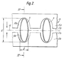
- the tubes 3 preferably have a largest outside diameter a (FIG. 2), here briefly referred to as “large diameter”, which is 2.5 times to 8 times larger than the smallest outside diameter b , here briefly referred to as “small diameter” is so that their ratio is 2.5: 1 to 8: 1.
- the tubes 3 can, as indicated in FIG. 3, also be arranged in two or more rows running parallel to the small diameter b .
- the large diameter a is 12.4 mm and the small diameter b is 3.6 mm and the tubes have a wall thickness of 0.4 mm.
- the tubes 3 are already firmly connected to the guide plates 1 and form a so-called heat exchanger network 11 (FIG. 1) with these. This connection is made as is generally known in particular in the manufacture of oil or water coolers for motor vehicles.
- the base plate 7 is further provided with sealing elements 12 (FIGS. 4, 5) which have through openings 13 aligned with the openings 5 and sealing collars 14 attached to them.
- the sealing elements 12, which can be connected to a one-piece or multi-piece sealing mat or plate extending over the width and length of the base plate 7, are arranged loosely and in such a way on one side of the base plate 7 that the sealing collar 14 from there into the Collar 8 of the base plate 7 protrude and lie firmly against it from the inside (FIGS. 4, 5).
- the sealing elements 12 are sufficiently elastic for example, they are made from an elastomer.
- a pressing tool 15 (FIG. 2) is preferably used, which consists of two plate-shaped pressing or molding jaws 15a, 15b, which run parallel to the axis 16 of the pressing tool 15 and have longitudinal edges 17a, 17b facing one another , which are preferably arranged straight and also parallel to the axis 16.
- the clear distance of the shaped pockets 18a, b parallel to the axis 16 corresponds to the clear distance of the tubes 3 within a row.
- the large diameter in the exemplary embodiment is 11.1 mm and the small diameter is 6.6 mm.
- the thickness of the plate-shaped pressure jaws 15a, b is preferably approximately as large as the length of the sealing collar 14 in the axial direction thereof, plus a tube protrusion projecting beyond the sealing elements, which serves to compensate for the length and angularity tolerances of the tubes and base plates, and plus a transition area with the length l (Fig. 4), the smooth transition between the pre-pressed pipe end and the pipe sections unchanged in cross section in the network.
- the pressure jaws 15a, b are placed according to FIGS. 2 and 3 from the top of the heat exchanger network 11 onto the ends of the tubes 3 protruding therefrom and then with mechanical, pneumatic, hydraulic or electrical means (not shown) in the direction of the arrows (FIG. 2) braced until their longitudinal edges 17a, b lie against each other, and then detached from each other in the opposite direction to the arrow.
- the tube ends are deformed from the outside (Fig. 3) that their large diameter reduced to 11.1 mm and their small diameters increased to 6.6 mm and therefore the tube ends are given an outer contour corresponding to the inner contour of the recesses 19.
- a line 20 indicates the cross-sectional shape of the pipe ends in the original state, since the remaining sections of the pipes 3 bordering on the deformed pipe ends and having the unchanged cross section are partially visible in the plan view.
- heat exchanger networks are provided with a plurality of rows of tubes 3, as indicated schematically in FIG. 3, each row of tubes is treated accordingly, the individual rows preferably being treated in cycles with the same pressing tool 15.
- the base plate 7 provided with the sealing elements 12 is now placed on the heat exchanger network 11 in the manner shown in FIG. 4, in which, on an exaggerated scale, a space allowing the insertion of the pipe ends into the sealing collar 14 is shown. In fact, this free space is only about one to two tenths of a millimeter, for example.
- the base plate 7 is of course provided with one or more rows of openings 5 corresponding to the number of rows of pipes present.
- the final attachment of the base plate 7 to the heat exchanger network 11 is carried out in that the tube ends are widened in a manner known per se by introducing a mandrel 21.
- a number of mandrels 21 corresponding to the number of pipe ends is preferably provided, which are fastened to a common drive device via support elements 22.
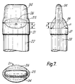
- the mandrel 21 has an oval outer cross section, which runs out via inclined surfaces 23 into a tip 24 that can be inserted into the pipe ends.
- the outer cross section of the mandrel 21 is selected, for example, such that the tube ends are widened to a large diameter of 12 mm and a small diameter of 7.9 mm by inserting the mandrels 21 once on their outer circumference.
- the elastic wall parts of the sealing collar 14 are expanded in the direction of their large diameters by 0.35 mm each and in the direction of their small diameters by 0.55 mm each, ie the pipe ends in them in the direction of the small diameters more tense.
- this expansion of the pipe ends is preferably carried out in two steps, each step taking place in two stages.
- a first expansion step the mandrels 21 according to FIG. 7 are used, the large and small diameters m and n of which are, for example, 0.6 mm smaller than the final, full inner diameters of the pipe ends.
- mandrels 21 according to FIG. 7 are then also used, in which the diameters m and n correspond to the final dimensions of the pipe ends.
- each step is also carried out in two stages in the sense that the tube ends in the insertion direction of the mandrels 21 first gradually over the large diameter and then gradually while maintaining the value achieved thereby over the small diameter, i.e. be expanded across the long sides.
- This procedure has compared to a uniform and simultaneous expansion in all directions, e.g. the advantage that in the formation of the particularly crack-sensitive pipe sections having the small pipe radii, material from the adjacent pipe sections having the large pipe radii can flow into them, since the latter do not yet lie against the mandrel flanks at this point and therefore do not yet come into contact with static friction these are held.
- the tips 24 of the mandrels 21 are also knife-like and are designed such that the tubes do not collapse in the transition regions from the widened tube ends to the intermediate tube sections and thereby reduce the tube cross sections in these regions.
- This collapse of the tubes 3 could result from the thrust occurring in the longitudinal direction of the tubes 3 during the insertion of the mandrel.
- the tip 24 is shaped so that its small diameter is slightly smaller than the small inner diameter of that within the heat exchanger network 11 located, middle pipe sections and their large diameter is slightly smaller than the large inner diameter of the pipe ends after pressing. This ensures that the long side walls of the tubes 3 only contact and support the tip 24 when they actually buckle inwards.
- the tip 24 is followed by a mandrel section 25 which leads in the direction of insertion, which brings about the above-explained first expansion step in the direction of the large diameter to a preselected value and whose large diameter gradually increases from the tip to the diameter m and thereafter remains essentially constant until the other end of the mandrel.
- the mandrel section 25 - viewed in the direction of insertion - is followed by a trailing mandrel section 26. This causes the second expansion step explained above in the direction of the small diameter to the preselected value. Its small diameter therefore has a value gradually increasing from the tip 25 to the diameter n , which then remains essentially constant up to the other end of the mandrel.
- the dimension k is also used to denote the difference by which the full large diameter m - viewed in the direction of insertion of the mandrel 21 - is reached earlier than the full small diameter n when the pipe ends are widened.
- the two mandrel sections 25, 26 can lie one behind the other in such a way that the widening in the direction of the small diameter only begins after the widening in the direction of the large diameter has been completed.
- the ends of the tubes 3 and the base plate 7 are now permanently connected to one another in accordance with FIG. 6.
- the heat exchanger network 11 which has been supplemented in this way can then be connected in a conventional manner to the lid of an associated collecting tank, the peripheral edge of which is inserted, for example, into a peripheral groove 27 provided with a sealant and which is then fastened to the base plate by bending clip clips.
- vibration welding, gluing or the like are also possible for connection, in particular in the case of base plates and lids made of plastic.
- a particular advantage of the external pressure is that the tubes 3 are deformed, but their scope remains essentially unchanged. Therefore, the forming process takes place without stretching the pipe walls and the resulting work hardening of the material layers involved, so that during the final expansion there is no danger that the pipe walls or collars will tear.
- the expansion can take place in such a way that the sealing collar 14 is preloaded evenly radially in all directions, ie essentially radially to an imaginary central axis, but also with a preferred direction, for example parallel to the smallest diameters, if this is used to preload the individual case Sealing collar is appropriate.
- Another significant advantage of the method according to the invention is that the large diameter of the tubes can be chosen larger than the large diameter of the tube ends after expansion. This makes it possible to produce compact, narrow heat exchangers in which the smallest distance between the walls of the tubes 3 in the heat exchanger network (dimension c in FIG. 6) in the direction of the large diameters is smaller than the corresponding distance between the insides of the sealing collars after they have been inserted into the Collar of the bottom plate is.
- the method according to the invention is therefore particularly suitable for connecting heat exchanger networks to metal base plates, in which, in contrast to plastic base plates, this distance is limited for manufacturing reasons.
- Another important advantage is that the expansion can be done without gradation and thus the pipe
- the specified diameter ratios of the heat exchanger can be varied within wide limits. Diameter ratios of preferably 2.5: 1 to 5: 1, but also those of 5: 1 to 8: 1 for the tubes 3 of the heat exchanger network and from 1.2: 1 to 3: 1 at the tube ends in the fully assembled heat exchanger have been found proven to be particularly suitable. It would be because of the adaptation of the cross-sections of the pipe ends by deformation to a cross-section which essentially corresponds to the cross-section of the sealing collar It is also conceivable to carry out this deformation in a different way, for example from the inside, provided that this only results in a deformation with an essentially constant extent.
- the invention is not limited to the use of base plates with the collars 8 on display. In particular when using plastic base plates, these collars 8 can be dispensed with entirely.
- oval tube cross sections in the strictly mathematical sense.
- oval is to be understood to mean all such cross-sectional shapes which are generally referred to as oval, elliptical, egg-shaped or the like or in the sense of "flat oval” in that they have two parallel, straight sides , the ends of which are connected to one another by oval, elliptical, semicircular or the like.
- the pipe sections located between the machined ends should have a ratio of the large to the small diameter of 2.5: 1 to 8: 1.
Landscapes
- Engineering & Computer Science (AREA)
- Mechanical Engineering (AREA)
- Physics & Mathematics (AREA)
- Thermal Sciences (AREA)
- General Engineering & Computer Science (AREA)
- Heat-Exchange Devices With Radiators And Conduit Assemblies (AREA)
- Automatic Assembly (AREA)
- Details Of Heat-Exchange And Heat-Transfer (AREA)
- Steam Or Hot-Water Central Heating Systems (AREA)
- Physical Or Chemical Processes And Apparatus (AREA)
- Lining Or Joining Of Plastics Or The Like (AREA)
Claims (10)
- Echangeur de chaleur avec un réseau d'échange thermique (11), qui comporte une multiplicité de tubes (3) de section ovale et d'extrémités de tubes, d'une forme de section différente de la forme circulaire, et avec une plaque d'extrémité (6, 7), fixée sur les extrémités de tubes par élargissement de ces dernières, et qui présente une multiplicité d'ouvertures (5) et d'éléments d'étanchéité (12), avec des orifices de passage (13) alignés sur les ouvertures (5) et munis de collets d'étanchéité (14), enveloppant les extrémités de tubes et disposés dans les ouvertures (5), le rapport diamétral des tubes étant plus élevé que le rapport diamétral des extrémités de tubes, caractérisé en ce que le rapport diamétral des tubes (3) est de 2,5 : 1 à 8 : 1, et en ce que les extrémités de tubes sont formées par emboutissage de l'extérieur, suivi d'un élargissement de l'intérieur, de sorte qu'elles présentent un rapport diamétral de 1,2 : 1 à 3 : 1 dans la zone de la plaque d'extrémité (6, 7).
- Echangeur de chaleur suivant la revendication 1, caractérisé en ce que les grands diamètres des tubes (3) sont supérieurs aux grands diamètres des extrémités de tubes dans la zone de la plaque d'extrémité.
- Procédé de fabrication d'un échangeur de chaleur suivant l'une des revendications 1 et 2, caractérisé en ce que les extrémités de tubes sont formées par emboutissage de l'extérieur en une forme, différente de la forme circulaire, sont introduites dans les orifices de passage (13), puis sont élargies de l'intérieur dans toutes les directions, à la transversale de leur sens longitudinal, et ainsi appliquées sur les collets d'étanchéité (14), d'une manière étanche aux liquides, la déformation des extrémités de tubes étant assurée, de sorte qu'elles présentent un rapport diamétral de 1,2 : 1 à 3 : 1 après l'élargissement.
- Procédé suivant la revendication 3, caractérisé en ce que les sections des orifices de passages (13) ont une réalisation ovale et sont choisies, de manière à n'être que légèrement supérieures aux sections des extrémités de tubes, obtenues après l'emboutissage.
- Procédé suivant l'une des revendications 3 et 4, caractérisé en ce que l'élargissement est assuré de manière que le grand diamètre des extrémités de tubes reste inférieur au grand diamètre des tubes (3).
- Procédé suivant l'une quelconque des revendications 3 à 5, caractérisé en ce que l'élargissement est assuré en deux étapes.
- Procédé suivant la revendication 6, caractérisé en ce que chaque étape est réalisée en deux phases, le grand diamètre intégral des extrémités de tubes étant alors obtenu avant leur petit diamètre intégral.
- Procédé suivant l'une quelconque des revendications 3 à 7, caractérisé en ce que des mandrins (21) sont introduits dans les extrémités de tubes pour leur élargissement, ces mandrins présentant, dans le sens d'introduction, une première section de mandrin (25), précédente, produisant un grand diamètre présélectionné, et une seconde section de mandrin (26), suivante, produisant un petit diamètre présélectionné.
- Procédé suivant la revendication 8, caractérisé en ce qu'un fléchissement des tubes (3) dans les zones de transition entre les extrémités de tubes et les sections de tubes intermédiaires centrales est évité au moyen de pointes (24) des mandrins (21), précédant les premières sections de mandrins (25).
- Procédé suivant l'une quelconque des revendications 3 à 9, caractérisé en ce que l'emboutissage est assuré de manière que le pourtour des extrémités de tubes reste essentiellement inchangé.
Applications Claiming Priority (2)
| Application Number | Priority Date | Filing Date | Title |
|---|---|---|---|
| DE3908266A DE3908266A1 (de) | 1989-03-14 | 1989-03-14 | Waermeaustauscher und verfahren zur fluessigkeitsdichten befestigung einer bodenplatte an einem waermetauschernetz |
| DE3908266 | 1989-03-14 |
Publications (2)
| Publication Number | Publication Date |
|---|---|
| EP0387678A1 EP0387678A1 (fr) | 1990-09-19 |
| EP0387678B1 true EP0387678B1 (fr) | 1993-11-24 |
Family
ID=6376307
Family Applications (1)
| Application Number | Title | Priority Date | Filing Date |
|---|---|---|---|
| EP90104324A Expired - Lifetime EP0387678B1 (fr) | 1989-03-14 | 1990-03-07 | Echangeur de chaleur et procédé pour la fixation étanche des éléments d'échange dans une plaque d'extrémité |
Country Status (9)
| Country | Link |
|---|---|
| US (1) | US5101561A (fr) |
| EP (1) | EP0387678B1 (fr) |
| JP (1) | JP3198385B2 (fr) |
| KR (1) | KR0144564B1 (fr) |
| AT (1) | ATE97734T1 (fr) |
| CA (1) | CA2012043C (fr) |
| DE (2) | DE3908266A1 (fr) |
| DK (1) | DK0387678T3 (fr) |
| ES (1) | ES2048877T3 (fr) |
Families Citing this family (30)
| Publication number | Priority date | Publication date | Assignee | Title |
|---|---|---|---|---|
| FR2676534B1 (fr) * | 1991-05-14 | 1999-02-12 | Valeo Thermique Moteur Sa | Echangeur de chaleur a faisceau de tubes, en particulier pour vehicule automobile, et procede pour sa fabrication. |
| HU9200588D0 (en) * | 1992-02-24 | 1992-05-28 | Energiagazdalkodasi Intezet | Pipe joint consisting of pipe wall and pipe as well as method for producing said joint |
| DE4212717A1 (de) * | 1992-04-16 | 1993-10-21 | Laengerer & Reich Gmbh & Co | Wärmeaustauscher |
| FR2690515A1 (fr) * | 1992-04-24 | 1993-10-29 | Valeo Thermique Moteur Sa | Echangeur de chaleur à tubes de section oblongue, en particulier pour véhicules automobiles. |
| DE4305945A1 (de) * | 1993-02-26 | 1994-09-01 | Behr Gmbh & Co | Wärmetauscher, insbesondere für Kraftfahrzeuge |
| DE4311892A1 (de) * | 1993-04-10 | 1994-10-13 | Behr Gmbh & Co | Wärmetauscher, insbesondere für Kraftfahrzeuge |
| US5341566A (en) * | 1993-05-10 | 1994-08-30 | Eaton Corporation | Conduit attachment |
| DE4316020C1 (de) * | 1993-05-13 | 1994-04-28 | Laengerer & Reich Gmbh & Co | Flachrohr für Wärmeaustauscher |
| DE4445590C2 (de) * | 1994-12-20 | 2001-02-01 | Behr Gmbh & Co | Verfahren zum Aufweiten der Rohrenden von Rohren eines Wärmetauschers, Werkzeug zur Durchführung des Verfahrens sowie nach dem Verfahren und mit dem Werkzeug hergestellter Wärmetauscher |
| US5604982A (en) * | 1995-06-05 | 1997-02-25 | General Motors Corporation | Method for mechanically expanding elliptical tubes |
| FR2740869B1 (fr) | 1995-11-02 | 1997-12-19 | Valeo Thermique Moteur Sa | Echangeur de chaleur a tubes de section ovale ou oblongue et son procede d'assemblage |
| US5655298A (en) * | 1996-05-23 | 1997-08-12 | Greene Manufacturing Co. | Method for joining a tube and a plate |
| DE69806070D1 (de) * | 1998-03-31 | 2002-07-18 | I S C Ind Scambiatori Calore S | Verfahren zur herstellung einer flüssigkeitsdichten verbindung zwischen einem rohr und einem metallplattenteil |
| DE19836015C2 (de) * | 1998-08-10 | 2002-06-13 | Behr Gmbh & Co | Verfahren zum Aufweiten von Rohrenden von Rohren eines Wärmetauschers |
| FR2794852B1 (fr) * | 1999-06-08 | 2001-08-31 | Valeo Thermique Moteur Sa | Echangeur de chaleur comprenant une rangee de tubes traversant des trous d'une plaque collectrice |
| US6151949A (en) * | 1999-08-25 | 2000-11-28 | Visteon Global Technologies, Inc. | Method of manufacturing a flat corrugated tube |
| DE60100617T2 (de) | 2000-10-06 | 2004-06-09 | Visteon Global Technologies, Inc., Dearborn | Herstellung eines Rohres für einen Wärmetauscher |
| DE10123675B4 (de) * | 2001-05-16 | 2019-05-29 | Mahle International Gmbh | Wärmeübertrager |
| DE10132617A1 (de) * | 2001-07-05 | 2003-01-16 | Modine Mfg Co | Wärmeaustauscher |
| JP4239840B2 (ja) * | 2004-02-03 | 2009-03-18 | 株式会社デンソー | 熱交換器用チューブの口拡治具 |
| JP4687890B2 (ja) * | 2005-10-28 | 2011-05-25 | トヨタ自動車株式会社 | 金属曲げ管の矯正方法および矯正用プレス金型 |
| US20070227713A1 (en) * | 2006-03-31 | 2007-10-04 | Bugler Thomas W Iii | Heat exchanger tube with a compressed return bend, a serpentine heat exchanger tube with compressed return bends and heat exchanger implementing the same |
| US7296620B2 (en) * | 2006-03-31 | 2007-11-20 | Evapco, Inc. | Heat exchanger apparatus incorporating elliptically-shaped serpentine tube bodies |
| CN101432225B (zh) * | 2006-04-26 | 2012-04-04 | 松下电器产业株式会社 | 氢生成装置的制造方法 |
| FR2906355B1 (fr) * | 2006-09-21 | 2009-02-27 | Valeo Systemes Thermiques | Tube pour echangeur de chaleur,echangeur comportant un tel tube et procede de fabrication d'un tel tube |
| US9437903B2 (en) * | 2012-01-31 | 2016-09-06 | Johnson Controls Technology Company | Method for cooling a lithium-ion battery pack |
| US20150136369A1 (en) * | 2012-06-08 | 2015-05-21 | International Engine Intellectual Property Company Llc | Egr cooler header casting |
| WO2018131434A1 (fr) * | 2017-01-12 | 2018-07-19 | 三菱電機株式会社 | Outil d'expansion, dispositif d'expansion, procédé d'expansion pour tube de chauffage, et procédé de fabrication d'un échangeur de chaleur |
| DE102017216639A1 (de) * | 2017-09-20 | 2019-03-21 | Mahle International Gmbh | Wärmetauscher |
| DE102020216059A1 (de) * | 2020-12-16 | 2022-06-23 | Mahle International Gmbh | Verfahren zur Herstellung eines Wärmeübertragers |
Citations (2)
| Publication number | Priority date | Publication date | Assignee | Title |
|---|---|---|---|---|
| DE3505492A1 (de) * | 1985-02-16 | 1986-08-21 | Thermal-Werke Wärme-Kälte-Klimatechnik GmbH, 6832 Hockenheim | Wasserkasten fuer waermetauscher |
| US4739828A (en) * | 1985-09-12 | 1988-04-26 | Sueddeutsche Kuehlerfabrik Julius Fr. Behr Gmbh. & Co. Kg | Heat exchanger |
Family Cites Families (17)
| Publication number | Priority date | Publication date | Assignee | Title |
|---|---|---|---|---|
| US2573161A (en) * | 1947-12-12 | 1951-10-30 | Trane Co | Heat exchanger |
| FR1577223A (fr) * | 1967-07-21 | 1969-08-08 | ||
| US3972371A (en) * | 1972-04-26 | 1976-08-03 | Societe Anonyme Des Usines Chausson | Tube and tube-plate assembly |
| DE2747275A1 (de) * | 1977-10-21 | 1979-04-26 | Volkswagenwerk Ag | Waermetauscher, insbesondere leichtmetall-waermetauscher |
| FR2462215A1 (fr) * | 1979-07-26 | 1981-02-13 | Ferodo Sa | Procede de conformation d'un tube en particulier pour echangeur de chaleur et echangeur de chaleur muni de tubes ainsi conformes |
| FR2462214A1 (fr) * | 1979-07-26 | 1981-02-13 | Ferodo Sa | Procede de conformation d'un tube, en particulier pour echangeur de chaleur |
| FR2474674B1 (fr) * | 1980-01-24 | 1986-03-14 | Ferodo Sa | Tube pour echangeur de chaleur a corps de section oblongue et extremite cylindrique |
| FR2475709B1 (fr) * | 1980-02-08 | 1985-12-06 | Chausson Usines Sa | Tube pour echangeur de chaleur et echangeur a plaque collectrice et a assemblage mecanique comportant ce tube |
| FR2512941B1 (fr) * | 1981-09-14 | 1987-04-24 | Valeo | Echangeur de chaleur a faisceau de tubes paralleles et procede d'assemblage de ses elements constitutifs |
| JPS5929994A (ja) * | 1982-08-11 | 1984-02-17 | Ntn Toyo Bearing Co Ltd | 熱交換器 |
| DE3232297C2 (de) * | 1982-08-31 | 1985-05-09 | Süddeutsche Kühlerfabrik Julius Fr. Behr GmbH & Co KG, 7000 Stuttgart | Verfahren zum Verbinden von ineinandergesteckten rohrförmigen Teilen eines Wärmetauschers und Werkzeug zur Durchführung des Verfahrens |
| FR2567247B1 (fr) * | 1984-07-05 | 1986-12-19 | Valeo | Procede de montage a etancheite de l'extremite d'un tube dans un trou d'une paroi, et echangeur de chaleur a faisceau de tubes realise par execution de ce procede |
| DE3432073A1 (de) * | 1984-08-31 | 1986-03-06 | Dirk Dipl.-Wirtsch.-Ing. 3500 Kassel Pietzcker | Waermetauscher, insbesondere fuer kraftfahrzeuge, und vorrichtung und verfahren zum verbinden von dessen rohren und lamellen |
| US4570317A (en) * | 1985-01-18 | 1986-02-18 | Ford Motor Company | Method of attaching a tube to a fin |
| US4730669A (en) * | 1986-02-03 | 1988-03-15 | Long Manufacturing Ltd. | Heat exchanger core construction utilizing a diamond-shaped tube-to-header joint configuration |
| US4720902A (en) * | 1986-12-22 | 1988-01-26 | Carrier Corporation | One step tension expander and method of using |
| US4766667A (en) * | 1986-12-22 | 1988-08-30 | Carrier Corporation | Apparatus for tension expanding tubes |
-
1989
- 1989-03-14 DE DE3908266A patent/DE3908266A1/de not_active Withdrawn
-
1990
- 1990-03-07 ES ES90104324T patent/ES2048877T3/es not_active Expired - Lifetime
- 1990-03-07 DK DK90104324.0T patent/DK0387678T3/da active
- 1990-03-07 AT AT90104324T patent/ATE97734T1/de not_active IP Right Cessation
- 1990-03-07 DE DE90104324T patent/DE59003568D1/de not_active Expired - Fee Related
- 1990-03-07 EP EP90104324A patent/EP0387678B1/fr not_active Expired - Lifetime
- 1990-03-13 CA CA002012043A patent/CA2012043C/fr not_active Expired - Fee Related
- 1990-03-13 JP JP06248590A patent/JP3198385B2/ja not_active Expired - Fee Related
- 1990-03-14 KR KR1019900003376A patent/KR0144564B1/ko not_active IP Right Cessation
- 1990-03-14 US US07/493,465 patent/US5101561A/en not_active Expired - Lifetime
Patent Citations (2)
| Publication number | Priority date | Publication date | Assignee | Title |
|---|---|---|---|---|
| DE3505492A1 (de) * | 1985-02-16 | 1986-08-21 | Thermal-Werke Wärme-Kälte-Klimatechnik GmbH, 6832 Hockenheim | Wasserkasten fuer waermetauscher |
| US4739828A (en) * | 1985-09-12 | 1988-04-26 | Sueddeutsche Kuehlerfabrik Julius Fr. Behr Gmbh. & Co. Kg | Heat exchanger |
Also Published As
| Publication number | Publication date |
|---|---|
| JP3198385B2 (ja) | 2001-08-13 |
| KR900014849A (ko) | 1990-10-25 |
| EP0387678A1 (fr) | 1990-09-19 |
| ATE97734T1 (de) | 1993-12-15 |
| CA2012043C (fr) | 2000-06-13 |
| ES2048877T3 (es) | 1994-04-01 |
| CA2012043A1 (fr) | 1990-09-14 |
| DE59003568D1 (de) | 1994-01-05 |
| KR0144564B1 (ko) | 1998-08-01 |
| DK0387678T3 (da) | 1994-02-07 |
| JPH02279991A (ja) | 1990-11-15 |
| US5101561A (en) | 1992-04-07 |
| DE3908266A1 (de) | 1990-09-20 |
Similar Documents
| Publication | Publication Date | Title |
|---|---|---|
| EP0387678B1 (fr) | Echangeur de chaleur et procédé pour la fixation étanche des éléments d'échange dans une plaque d'extrémité | |
| EP0176729B1 (fr) | Echangeur de chaleur, ainsi que procédé et dispositif pour sa fabrication | |
| DE4340378C2 (de) | Wärmeaustauscher und Verfahren zur Herstellung derselben | |
| EP0379701B1 (fr) | Echangeur de chaleur | |
| DE3141580A1 (de) | Waermetauscher mit mechanisch zusammengefuegten rohren, rippen und sammelplatten | |
| DE3425382C2 (de) | Verfahren zur Herstellung des Kernes eines Röhrenwärmeaustauschers | |
| EP0672882A1 (fr) | Ailette pour échangeur de chaleur | |
| DE2839142A1 (de) | Rippenrohranordnung fuer waermetauscher | |
| DE2714757B2 (de) | Rohrplatte mit in deren Löchern befestigten Rohren für insbesondere Wärmetauscher | |
| DE102006028490A1 (de) | Verfahren zum Herstellen eines Sammelrohres, Sammeltank mit Sammelrohr und Wärmeaustauscher mit Sammeltank | |
| DE3104010A1 (de) | Waermetauscherrohr und waermetauscher mit sammelplatte und mechanischem zusammenbau mit dem waermetauscherrohr | |
| EP0566899B1 (fr) | Echangeur de chaleur, notamment évaporateur | |
| EP0929784B1 (fr) | Echangeur de chaleur a tubes aplatis retenus sur des collets d'un fond a tubes pour vehicules a moteur | |
| EP0565813B1 (fr) | Echangeur de chaleur | |
| DE2241407B2 (de) | Verfahren zur Herstellung eines Wärmetauscherelements | |
| DE4432972A1 (de) | Wärmetauscher mit zwei Rohrreihen, insbesondere für Kraftfahrzeuge | |
| DE19800943A1 (de) | Wärmerohr für einen Wärmetauscher | |
| DE3131736A1 (de) | Verfahren zur herstellung von waermetauschern mit rundgebogenen teilen, sowie gemaess dem verfahren hergestellter waermetauscher | |
| DE4334203C2 (de) | Werkzeug zum Einbringen von Durchzügen in ein Sammelrohr eines Wärmetauschers | |
| DE3834822A1 (de) | Waermetauscher | |
| DE2813952A1 (de) | Rohrboden aus metall, anwendungen und verwendung desselben sowie verfahren und vorrichtung zu seiner herstellung | |
| EP0253167B1 (fr) | Echangeur de chaleur, en particulier évaporateur pour réfrigérant | |
| DE102005058177A1 (de) | Verfahren zur Herstellung eines Wärmeaustauschers | |
| DE102006012625B4 (de) | Verfahren zur Herstellung von Profilen | |
| DE3401853A1 (de) | Waermetauscher und verfahren zu seiner herstellung |
Legal Events
| Date | Code | Title | Description |
|---|---|---|---|
| PUAI | Public reference made under article 153(3) epc to a published international application that has entered the european phase |
Free format text: ORIGINAL CODE: 0009012 |
|
| AK | Designated contracting states |
Kind code of ref document: A1 Designated state(s): AT BE CH DE DK ES FR GB GR IT LI LU NL SE |
|
| 17P | Request for examination filed |
Effective date: 19901217 |
|
| 17Q | First examination report despatched |
Effective date: 19920203 |
|
| GRAA | (expected) grant |
Free format text: ORIGINAL CODE: 0009210 |
|
| AK | Designated contracting states |
Kind code of ref document: B1 Designated state(s): AT BE CH DE DK ES FR GB GR IT LI LU NL SE |
|
| PG25 | Lapsed in a contracting state [announced via postgrant information from national office to epo] |
Ref country code: GR Free format text: LAPSE BECAUSE OF FAILURE TO SUBMIT A TRANSLATION OF THE DESCRIPTION OR TO PAY THE FEE WITHIN THE PRESCRIBED TIME-LIMIT Effective date: 19931124 |
|
| REF | Corresponds to: |
Ref document number: 97734 Country of ref document: AT Date of ref document: 19931215 Kind code of ref document: T |
|
| REF | Corresponds to: |
Ref document number: 59003568 Country of ref document: DE Date of ref document: 19940105 |
|
| GBT | Gb: translation of ep patent filed (gb section 77(6)(a)/1977) |
Effective date: 19931217 |
|
| ITF | It: translation for a ep patent filed |
Owner name: ING. ZINI MARANESI & C. S.R.L. |
|
| REG | Reference to a national code |
Ref country code: DK Ref legal event code: T3 |
|
| ET | Fr: translation filed | ||
| PGFP | Annual fee paid to national office [announced via postgrant information from national office to epo] |
Ref country code: BE Payment date: 19940315 Year of fee payment: 5 Ref country code: AT Payment date: 19940315 Year of fee payment: 5 |
|
| PGFP | Annual fee paid to national office [announced via postgrant information from national office to epo] |
Ref country code: CH Payment date: 19940316 Year of fee payment: 5 |
|
| PGFP | Annual fee paid to national office [announced via postgrant information from national office to epo] |
Ref country code: NL Payment date: 19940331 Year of fee payment: 5 Ref country code: LU Payment date: 19940331 Year of fee payment: 5 |
|
| REG | Reference to a national code |
Ref country code: ES Ref legal event code: FG2A Ref document number: 2048877 Country of ref document: ES Kind code of ref document: T3 |
|
| EPTA | Lu: last paid annual fee | ||
| PLBI | Opposition filed |
Free format text: ORIGINAL CODE: 0009260 |
|
| 26 | Opposition filed |
Opponent name: BEHR GMBH & CO. -PATENTABTEILUNG- Effective date: 19940822 Opponent name: LAENGERER & REICH GMBH Effective date: 19940819 |
|
| NLR1 | Nl: opposition has been filed with the epo |
Opponent name: BEHR GMBH & CO. -PATENTABTEILUNG- Opponent name: LAENGERER & REICH GMBH |
|
| EAL | Se: european patent in force in sweden |
Ref document number: 90104324.0 |
|
| PG25 | Lapsed in a contracting state [announced via postgrant information from national office to epo] |
Ref country code: LU Free format text: LAPSE BECAUSE OF NON-PAYMENT OF DUE FEES Effective date: 19950307 Ref country code: AT Effective date: 19950307 |
|
| PG25 | Lapsed in a contracting state [announced via postgrant information from national office to epo] |
Ref country code: LI Effective date: 19950331 Ref country code: CH Effective date: 19950331 Ref country code: BE Effective date: 19950331 |
|
| PLBN | Opposition rejected |
Free format text: ORIGINAL CODE: 0009273 |
|
| STAA | Information on the status of an ep patent application or granted ep patent |
Free format text: STATUS: OPPOSITION REJECTED |
|
| BERE | Be: lapsed |
Owner name: AUTOKUHLER G.M.B.H. & CO. K.G. Effective date: 19950331 |
|
| PG25 | Lapsed in a contracting state [announced via postgrant information from national office to epo] |
Ref country code: NL Effective date: 19951001 |
|
| 27O | Opposition rejected |
Effective date: 19950624 |
|
| REG | Reference to a national code |
Ref country code: CH Ref legal event code: PL |
|
| NLV4 | Nl: lapsed or anulled due to non-payment of the annual fee |
Effective date: 19951001 |
|
| REG | Reference to a national code |
Ref country code: GB Ref legal event code: IF02 |
|
| PGFP | Annual fee paid to national office [announced via postgrant information from national office to epo] |
Ref country code: DK Payment date: 20030225 Year of fee payment: 14 |
|
| PGFP | Annual fee paid to national office [announced via postgrant information from national office to epo] |
Ref country code: SE Payment date: 20030312 Year of fee payment: 14 |
|
| PG25 | Lapsed in a contracting state [announced via postgrant information from national office to epo] |
Ref country code: SE Free format text: LAPSE BECAUSE OF NON-PAYMENT OF DUE FEES Effective date: 20040308 |
|
| PG25 | Lapsed in a contracting state [announced via postgrant information from national office to epo] |
Ref country code: DK Free format text: LAPSE BECAUSE OF NON-PAYMENT OF DUE FEES Effective date: 20040331 |
|
| EUG | Se: european patent has lapsed | ||
| PGFP | Annual fee paid to national office [announced via postgrant information from national office to epo] |
Ref country code: FR Payment date: 20050214 Year of fee payment: 16 |
|
| PGFP | Annual fee paid to national office [announced via postgrant information from national office to epo] |
Ref country code: GB Payment date: 20050302 Year of fee payment: 16 |
|
| PGFP | Annual fee paid to national office [announced via postgrant information from national office to epo] |
Ref country code: ES Payment date: 20050309 Year of fee payment: 16 |
|
| PGFP | Annual fee paid to national office [announced via postgrant information from national office to epo] |
Ref country code: DE Payment date: 20050510 Year of fee payment: 16 |
|
| PG25 | Lapsed in a contracting state [announced via postgrant information from national office to epo] |
Ref country code: GB Free format text: LAPSE BECAUSE OF NON-PAYMENT OF DUE FEES Effective date: 20060307 |
|
| PG25 | Lapsed in a contracting state [announced via postgrant information from national office to epo] |
Ref country code: ES Free format text: LAPSE BECAUSE OF NON-PAYMENT OF DUE FEES Effective date: 20060308 |
|
| PGFP | Annual fee paid to national office [announced via postgrant information from national office to epo] |
Ref country code: IT Payment date: 20060331 Year of fee payment: 17 |
|
| PG25 | Lapsed in a contracting state [announced via postgrant information from national office to epo] |
Ref country code: DE Free format text: LAPSE BECAUSE OF NON-PAYMENT OF DUE FEES Effective date: 20061003 |
|
| GBPC | Gb: european patent ceased through non-payment of renewal fee |
Effective date: 20060307 |
|
| REG | Reference to a national code |
Ref country code: FR Ref legal event code: ST Effective date: 20061130 |
|
| REG | Reference to a national code |
Ref country code: ES Ref legal event code: FD2A Effective date: 20060308 |
|
| PG25 | Lapsed in a contracting state [announced via postgrant information from national office to epo] |
Ref country code: FR Free format text: LAPSE BECAUSE OF NON-PAYMENT OF DUE FEES Effective date: 20060331 |
|
| PG25 | Lapsed in a contracting state [announced via postgrant information from national office to epo] |
Ref country code: IT Free format text: LAPSE BECAUSE OF NON-PAYMENT OF DUE FEES Effective date: 20070307 |