EP0443964A1 - Niederleistungsmetallhalogenidlampe - Google Patents
Niederleistungsmetallhalogenidlampe Download PDFInfo
- Publication number
- EP0443964A1 EP0443964A1 EP91420043A EP91420043A EP0443964A1 EP 0443964 A1 EP0443964 A1 EP 0443964A1 EP 91420043 A EP91420043 A EP 91420043A EP 91420043 A EP91420043 A EP 91420043A EP 0443964 A1 EP0443964 A1 EP 0443964A1
- Authority
- EP
- European Patent Office
- Prior art keywords
- lamp
- arc chamber
- recited
- electrodes
- pair
- Prior art date
- Legal status (The legal status is an assumption and is not a legal conclusion. Google has not performed a legal analysis and makes no representation as to the accuracy of the status listed.)
- Granted
Links
Images

Classifications
-
- H—ELECTRICITY
- H01—ELECTRIC ELEMENTS
- H01J—ELECTRIC DISCHARGE TUBES OR DISCHARGE LAMPS
- H01J61/00—Gas-discharge or vapour-discharge lamps
- H01J61/02—Details
- H01J61/54—Igniting arrangements, e.g. promoting ionisation for starting
- H01J61/547—Igniting arrangements, e.g. promoting ionisation for starting using an auxiliary electrode outside the vessel
-
- H—ELECTRICITY
- H01—ELECTRIC ELEMENTS
- H01J—ELECTRIC DISCHARGE TUBES OR DISCHARGE LAMPS
- H01J61/00—Gas-discharge or vapour-discharge lamps
- H01J61/02—Details
- H01J61/12—Selection of substances for gas fillings; Specified operating pressure or temperature
- H01J61/16—Selection of substances for gas fillings; Specified operating pressure or temperature having helium, argon, neon, krypton, or xenon as the principle constituent
-
- H—ELECTRICITY
- H01—ELECTRIC ELEMENTS
- H01J—ELECTRIC DISCHARGE TUBES OR DISCHARGE LAMPS
- H01J61/00—Gas-discharge or vapour-discharge lamps
- H01J61/82—Lamps with high-pressure unconstricted discharge having a cold pressure > 400 Torr
- H01J61/827—Metal halide arc lamps
Definitions
- This invention relates in general to the field of metal halide arc discharge lamps and, in particular, to miniature low watt metal halide lamps of 35 watts or less achieving high efficacy and controlled color temperature performance.
- an envelope of vitreous silica material defines an arc chamber which contains a fill of mercury, inert gas, and metal halide. Sealed in the arc chamber is a pair of refractory tungsten electrodes having tips spaced apart from one another. After an arc discharge is established between the electrode tips, the temperature of the arc chamber rapidly increases, causing the mercury and metal halide to vaporize. The mercury atoms and metal atoms of the metal halide are ionized and excited, causing emissions of radiation at spectrums characteristic of the respective metals. This radiation is substantially combined within the arc chamber to produce a resultant light output having an established intensity and color temperature.
- the color temperature and efficacy are primarily dependent upon the vapor pressure of the halides in the arc chamber during lamp operation.
- Halide vapor pressure is strongly affected by the temperature of the wall of the envelope defining the arc chamber.
- the metal halide does not entirely vaporize during operation. In fact, a noticeable condensate exists in the cooler regions of the arc chamber. It has been long understood that this halide condensation, particularly in lower wattage lamps, can significantly reduce efficacy and increase color temperature to unacceptable levels. Moreover, for double-ended lamps, halide condensation generally occurs at the opposing ends where the electrodes emerge from the vitreous silica material. These end regions are normally the coolest in the arc chamber. For double-ended lamps, this result is especially disadvantageous in that the temperature of these end regions are sensitive to manufacturing variations and variations occuring over time. Hence, the efficacy and color temperature performance of these lamps can vary significantly over their lifetime and from one lamp to another. Such variations are unacceptable in many applications.
- Cap et al. U.S. Pat. No. 4,161,672 discloses that by reducing the cross-sectional area of the end shanks of the lamp envelope, the thermal loss through these shanks can be reduced.
- Cap et al. also discloses the use of opaque coatings of zirconiumoxide at the end regions to retain heat within the chamber.
- French et al. U.S. Pat. No. 4,808,876 and Waymouth et al. U.S. 3,324,332 also disclose the use of end coatings and reduced dimensions in the envelope end seals or shanks.
- French et al. and Waymouth et al. disclose the use of end chambers or wells at the ends of the arc chamber. The wells have a reduced cross-section from the main body of the arc chamber to increase the temperature at the end regions.
- Holle et al. U.S. Pat. No. 4,202,999 discloses that by reducing the physical size of the electrodes of miniature metal halide lamps, the heat loss through them is reduced, resulting in higher operational temperatures and higher efficacy.
- the various techniques described have not been sufficient to adequately reduce halide condensation in the end regions of the arc chamber.
- the disclosed lamp design requires that the tips of the electrodes be relatively close to the end regions in order to maintain an adequate vaporizing temperature in these regions. Therefore, the distance over which the electrodes can be inserted into the arc chamber (i.e. insertion depth) is restricted in these prior art metal halide lamps. Such a restriction on insertion depth necessarily imposes a limit on the spacing between the electrode tips (assuming acceptable wall loading requirements must be maintained). As will be described below, this limitation can result in low efficacy levels for miniature metal halide lamps having input power ratings of 35 watts and below.
- Another object of the present invention is to provide new miniature metal halide arc discharge lamps having power color temperature performance that has not been possible with prior art lamps.
- a further object of the present invention is to provide new miniature metal halide arc discharge lamps having power input ratings of 35 watts or less and achieving acceptable levels of efficacy and color temperature performance over the entire life of the lamps.
- Still another object of the present invention is to provide new miniature metal halide arc discharge lamps having power input ratings of 35 watts or less that are relatively insensitive to manufacturing variations.
- Yet another object of the present invention is provide new miniature metal halide arc discharge lamps having power input ratings of 35 watts or less and relatively short warm-up times.
- a metal halide arc discharge lamp having a power input rating of not more than 35 watts.
- the lamp comprises an envelope of light transmissive material including a bulb portion, a pair of transitional neck portions extending from the bulb portion, and a pair of stem portions extending from the transitional neck portions repectively.
- the bulb portion of the envelope defines an arc chamber therein and has an external surface area of such value as to produce a wall loading not exceeding about 35 watts cm2.
- Contained within the arc chamber is a fill of mercury, inert gas and metal halide. The mercury and metal halide are adapted to substantially vaporize during operation of the lamp.
- the lamp Extanding into the arc chamber from the beck portions is a pair of electrodes having alectrode tips spaced apart from one another by a distance A within the arc chamber.
- the neck portions of the envelope each have a wall surrounding a segment of the electrodes respectively.
- the walls of the neck portions each have a stretched section with a minimum wall thickness not exceeding 1.5 mm.
- the lamp also includes a pair of inlead assemblies electrically coupled to the pair of electrodes respectively. The inlead assemblies pass from the electrodes through a sealed section in the stem portions of the envelope to the exterior of the lamp.
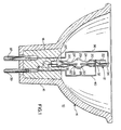
- a lamp and reflector assembly 10 is shown in a partial cross-sectional and elevational view.
- a miniature metal halide low watt arc discharge lamp 12, constructed according to the present invention, is shown based in an ellipsoid reflector 14.
- Lamp 12 is fixed into a collar 16 of reflector 14 with a ceramic or glassy cement compound 18.
- Cement compound 18 can be a zirconiumoxide product manufactured by Cotronics.
- Lamp 12 comprises an envelope of light transmissive material, such as vitreous silica.
- a fused quartz material is used, such as Type 214 manufactured by General Electric Company.
- the lamp envelope includes a pair of envelope shanks 20, 20′ which comprise stem portions 22, 22′ and transitional neck portions 24, 24′. Situated between envelope shanks 20 and 20′ is a bulb portion 26 of the lamp envelope.
- an arc chamber 28 Contained within arc chamber 28 is a chemical fill 29 of mercury and metal halide. As shown in Fig. 1, the mercury and metal halide are condensed on the interior surface of the wall of arc chamber 28 at room temperature. In addition to the metal halide and mercury, an inert gas, such as argon, occupies arc chamber 28 under a pressure of several hundred Torr.
- an inert gas such as argon
- Lamp 12 is designed to operate on a direct current (D.C.) input.
- D.C. direct current
- a pair of tungsten wire electrodes 30, 30′ project into arc chamber from neck portions 24, 24′.
- Electrode 30 is the cathode and electrode 30′ is the anode.
- Each electrode terminates at an electrode tip, within arc chamber 28, as is more clearly shown in Figs. 2 - 5.
- Electrodes 30, 30′ are connected to respective molybdenum ribbon foils 32, 32′ by lap welds.
- the envelope of lamp 12 is hermetically sealed at ribbon foils 32, 32′.
- stem portions 22, 22′ are heated until wetting of the quartz occurs around ribbon foils 32, 32′. Upon cooling, a hermetic seal is established about the foils.
- ribbon foils 32, 32′ Also connected to ribbon foils 32, 32′ are respective molybdenum wire inleads 34, 34′. The connections are effected by lap welds to ribbon foils 32, 32′.
- An assembly, including a ribbon foil and a wire inlead is referred to herein as an inlead assembly.
- An assembly, including a wire inlead, a ribbon foil and an electrode is referred to herein as an electrode assembly.
- Wire inlead 34 is electrically connected to a long contact rod 36 which is, in turn, connected to a pin conductor 37.
- Wire inlead 34′ is electrically connected to a short contact rod 38 which is, in turn, connected to a pin conductor 39.
- Also connected to short contact rod 38 is an external starting aid 40.
- Starting aid 40 will cause lamp 12 to start more reliably and at a lower value of starting voltage.
- Starting aid 40 is made of nickel and is positioned outside the quartz envelope of lamp 12.
- starting aid 40 From its connection at short contact rod 38, starting aid 40 extends to stem portion 22. Starting aid 40 is wrapped around stem portion 22 at ribbon foil 32, as shown in Fig. 1.
- the basic theory of operation and construction of starting aid 40 is well known in the lamp-making art. For example, U.S. Pat. No. 4,053,809 to Fridrich et al. discloses the basic teachings and construction of external starting devices.
- Wall loading is defined as the input watts into the lamp divided by the external radiating surface area of the arc chamber. As an approximation, the radiating surface is taken as the external surface of the envelope, excluding the end shanks. Excessive wall loading can cause envelope devitrification at an accelerated rate, resulting in poor lumen maintenance and shortened lamp life. For quartz envelopes having wall thicknesses of less than 1.5 mm, the wall loading should be less than 35 watts cm2 to ensure adequate lumen maintenance and lamp life.
- Arc loading is defined as the input watts into the lamp divided by the arc distance A.
- the arc distance is equivalent to the distance between the tips of the electrodes within the arc chamber. For a given power input, a short arc distance results in a high arc loading. High arc loadings result in higher efficacies for the low watt metal halide lamps of the present invention.
- Metal halide lamps of the prior art are hampered by a limitation on arc loading. This limitation stems from the requirement that the tips of the electrode are to remain relatively close to the end regions of the arc chamber. Under such a requirement, the only plausible way to decrease the arc distance is to reduce the arc chamber length. However, a reduction in the arc chamber length will usually result in a smaller radiating surface area of the arc chamber. A smaller surface area will, in turn, result in a higher wall loading. Therefore, if the chamber length is reduced beyond a certain point, the wall loading may exceed acceptable values.
- the lamps disclosed in Cap et al. U.S. Pat. No. 4,161,672 are designed not to exceed an arc loading of 150 watts /cm to avoid wall loadings above 35 watts cm2.
- the electrodes may be inserted a greater distance into the arc chamber than the prior art lamps, without experiencing unacceptable levels of halide condensation in the end regions.
- the insertion depth 1 of the electrodes can be much greater, for a given arc chamber length, than the prior art lamps. Greater insertion depths lead to shorter arc distances, which, in turn, result in higher lamp efficacy; and which, in turn, result in higher lamp efficacy; and higher efficacy is achieved without affecting wall loading.
- Y (W-A)/W.
- the insertion factors for the lamps of the present invention are generally much greater than those of prior art lamps due to the employment of greater insertion depths.
- the insertion factor is greater than a value of 0.6.
- the metal halide lamps of the present invention attain improvements in efficacy and control over color temperature because halide condensation is minimized in the end regions of the arc chamber during lamp operation.
- One aspect of the invention contributing to this result is the employment of very thin fused quartz walls in the transitional neck portion of the lamp envelope.
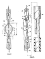
- Fig. 2 shows critical dimensional points of the lamp.
- transitional neck portions 52, 52′ have a minimum wall thickness designated as (n). It has been determined that wall thickness (n) should not exceed about 1.5 mm in order to retain the advantages of the present invention.
- transitional neck portions 52, 52′ are produced, in part, by stretching the quartz during manufacture of the lamp envelope.
- the step of stretching the quartz operates to compensate for the natural gathering or thickening of the quartz while it is being heated.
- thermal losses through neck portions 52, 52′ are minimized, resulting in hotter end regions in the arc chamber of the lamp.
- the arc chamber walls are made very thin, usually not exceeding about 0.5 mm.
- the envelope of lamp 50 has a bulb portion 54 with a wall thickness (t).
- Wall thickness (t) is defined over a centrally disposed segment of bulb portion 54, bounded by two imaginary parallel planes 56, 56′ that are located at the tips of the electrodes of lamp 50.
- the thermal losses through the wall of bulb portion 54 is minimized, resulting in higher arc chamber temperatures during lamp operation.
- the external surface area of bulb portion 54 is reduced for a given internal arc chamber volume. It is believed that this reduction in external surface area results in lower thermal diffusion from the quartz bulb to the ambient air.
- the wall of bulb portion 54 has a uniform thickness over the segment defined between imaginary parallel planes 56, 56′. Uniformity in the thickness of the wall results in lower thermal losses through the wall, and a more even thermal distribution within the arc chamber during operation of the lamp.
- the preferred geometries for the arc chamber of lamp 50 are ellipsoids and spheroids and approximation thereof.
- the proportions of the arc chamber can be expressed in terms of its internal length W and internal diameter D.
- the internal arc chamber length W is defined between the points where the electrodes emerge from the fused quartz envelope inside the arc chamber.
- the internal diameter D of the arc chamber is the diameter at the maximum transverse cross-section of the arc chamber. In most cases, this point is at or near the center of the arc chamber.
- a useful expression in considering arc chamber geometry is the aspect ratio.
- the aspect ratio of the arc chamber is defined by the ratio of arc chamber length W divided by internal diameter D (W/D).
- Metal halide lamps constructed in accordance with the present invention may have aspect ratios in the range of between 1.3 and 2.3.
- the insertion depth 1, of the electrodes of lamp 50 is defined as the distance over which the electrodes project into the arc chamber from the point where the electrodes emerge from the fused quartz envelope. It has been determined that for lamps designed with power inputs of between 11 and 35 watts, the insertion depth of the electrodes is to exceed 1.5 mm.
- Arc distance is a measure of the length of the arc produced between the electrodes of the lamp. This parameter is usually taken as the distance between the tips of the electrodes. As will be illustrated herein below with respect to Fig. 3-5, in many pratical embodiments of the present invention, arc distance A can be set to a value that will produce an arc loading greater than 150 w/cm.
- the internal volume of the arc chamber of lamp 50 will not exceed 0.3 cm3 for any size lamp of 35 watts or less.
- many practical embodiments of the present invention will have arc chamber volumes substantially smaller than 0.3 cm3.
- the chamber volume is less than .05 cm3.
- Another aspect of the present invention concerns the metal halide additives contained within the arc chamber of the lamp. It has been determined that in using the metal halides, sodium iodide and scandium tri-iodide, the percentage by weight of these additives is important in optimizing efficacy and controlling color temperature of the lamp. In most general illumination, optics and signal light applications, the percentages by weight are 87% sodium iodide and 13% scandium tri-iodide. It should be understood, however, that the present invention is not limited to the metal halides of sodium and scandium. Any of the metal halides know in the art can be employed in the lamps of the present invention. In particular, the bromide and iodide compounds from the group of elements consisting of scandium, thallium, lithium, zinc, mercury, dysprosium, indium, cadmium and sodium, are preferred.
- the warm-up time is defined as the time interval between the striking of the lamp with a start pulse and the achievement of steady - state operation.
- the lamps of the present invention have warm-up times of less than 30 seconds.
- the factors contributing to short warm-up times in the lamps of the present invention include, small diameter electrodes (less than 0.254 mm), relatively long insertion depths, small arc chamber volumes (less than 0.3 cm3), and low metal halide densities (less than 10 mg/cm3).
- Lamp 70 comprises a fused quartz envelope 72 having a bulb portion 74 and a pair of end shanks 76, 76′. End shanks 76, 76′ include respective transitional neck portions 78, 78′ and respective stem portions 80, 80′. Defined within the wall of bulb portion 74 is an arc chamber 82.
- arc chamber 82 Contained within arc chamber 82 is a fill of mercury, argon gas and the metal halides, sodium iodide and scandium tri- iodide.
- a pair of tungsten electrodes 84, 84′ extend into arc chamber 82 from neck portions 78, 78′ respectively. The tips of electrodes 84, 84′ are spaced apart from one another by a distance A within arc chamberr 82.
- Electrodes 84, 84′ are lap welded to respective molybdenum ribbon foils 86, 86′.
- Lamp envelope 72 is hermetically sealed at ribbon foils 86, 86′.
- a pair of molybdenum wire inlead 88, 88′ are lap welded respectively to ribbon foils 86, 86′.
- Electrodes 84, 84′ are straight shank tungsten wires of equal length, each having a flared tungsten tip cut at an angle. The shank of each electrode has a diameter of approximately 0.05 mm, and the tip flares out to a diameter of about 0.13 mm.
- a quartz tube casing 92 may be used to house lamp 70 for mounting lamp 70 into a fixture, such as the reflector shown in Fig. 1. Typical physical parameters and performance data of lamp 70 are shown in Table 1.
- the internal diameter D of arc chamber 82 may range between .08 and .11 cm.
- the length W of arc chamber 82 may range between .14 and .185 cm.
- the arc distance A may range between .075 and .28 mm.
- the wall thickness (t) of bulb portion 74 is approximately 0.11 mm.
- the diameter of electrodes 84, 84′ may range between .04 and .076 mm.
- the insertion depth 1 may range between 0.6 and 0.8 mm.
- the mercury loading may range between .096 and .112 mg, and the metal halide loading is approximately .025 mg.
- the metal halide loading comprises 87% sodium iodide and 13% scandium tri-iodide.
- the pressure of the argon gas, at room temperature, is approximately 540 Torr (10.44 PSI Absolute).
- the wall thickness (n) of neck portions 78, 78′ is less than 0.5 mm.
- the aspect ratio (W/D) may range between 1.3 and 2.3.
- the color temperature of lamp 70 is approximately 3,800oK.
- the warm-up time is less than 5 seconds. It is believed that these parameter ranges are applicable to lamps having power inputs of between 1.5 and 3.5 watts.
- Lamp 100 is made from a used quartz envelope 102 having a bulb portion 104 and a pair of end shanks 106, 106′. End shanks 106, 106′ include transitional neck portions 108, 108′ and stem portions 110, 110′.
- Bulb portion 104 has a wall defining an arc chamber 112.
- arc chamber 112 Contained within arc chamber 112 is a fill of mercury, argon gas and the metal halides, sodium iodide and scandium tri- iodide.
- a pair of tungsten electrodes 114, 114′ extend into arc chamber 112 from neck portions 108, 108′ respectively. The tips of electrodes 114, 114′ are spaced apart from one another by a distance A within arc chamber 112. Electrodes 114, 114′ are lap welded to respective molybdenum ribbon foils 116, 116′. Quartz envelope 102 is hermetically sealed at ribbon foils 116, 116′.
- a pair of molybdenum wire inleads 118, 118′ are lap welded respectively to ribbon foils 116, 116′.
- Lamp 100 is D.C. operated. Electrodes 114, 114′ are straight shank tungsten wire electrodes of equal length, each having a pointed tip. Electrode 114 is the cathode and has a diameter of 0.1524 mm. Electrode 114′ is the anode and has a diameter of 0.254 mm.
- the internal diameter D of arc chamber 112 may range between 0.29 and 0.32 cm.
- the length W of arc chamber 112 may range between 0.53 and 0.59 cm.
- the arc distance A may range between 0.5 to 0.8 mm.
- the aspect ratio (W/D) of arc chamber 112 may range between 1.7 and 2.
- An efficacy of 64 lumens per watt has been consistently achieved for the 12 watt metal halide lamp of the present invention.
- the insertion depth 1 may range between 2 and 2.8 mm.
- the wall thickness (t) of bulb portion 104 is approximately 0.26 mm. With these lamp parameters, the arc loading will exceed 150 watts /cm, with a wall loading of approximately 12 watts cm2.
- the wall thickness (n) of neck portions 108, 108′ is less than 1.5 mm and, in most cases, is less than 0.75 mm.
- the mercury loading is approximately 1.4 mg.
- the metal halide contained in arc chamber 112 comprises 87% sodium iodide and 13% scandium tri-iodide.
- the loading may range between 0.075 and 0.15 mg.
- the pressure of the argon gas, at room temperature, is 540 Torr (10.44 PSI Absolute).
- the color temperature of the lamp is 3,800oK; and the warm-up time is less than 12 sec. It is believed that these parameter ranges are applicable to lamps having power inputs of between 11 and 13 watts.
- Lamp 130 includes a fused quartz envelope 132 having a bulb portion 134 and a pair of end shanks 136, 136′. End shanks 136, 136′ include transitional neck portions 138, 138′ and stem portions 140, 140′. Bulb portion 134 has a wall defining an arc chamber 142 therein.
- arc chamber 142 Contained within arc chamber 142 is a fill of mercury, argon gas and the metal halides, sodium iodide and scandium tri-iodide.
- a pair of tungsten wire electrodes 144, 144′ extend into arc chamber 142 from stem portions 140, 140′ respectively. The tips of electrodes 144, 144′ are spaced apart from one another by a distance A within arc chamber 142. Electrodes 144, 144′ are lap welded to respective molybdenum ribbon foils 146, 146′. Envelope 142 is hermetically sealed at ribbon foils 146, 146′.
- a pair of molybdenum wire inleads 148′ are lap welded respectively to ribbon foils 146, 146′. As shown in Fig.
- lamp 130 comprises an external starting aid 150.
- Starting aid 150 is electrically connected to wire inlead 148′ at one end, and is wrapped around the exterior surface of stem portion 140 at the other end. Its function is identical to that described with respect to starting aid 40.
- Lamp 130 is D.C. operated.
- Electrodes 144, 144′ are straight shank tungsten wire electrodes of equal length, each having a pointed tip.
- Electrode 144 is the cathode and has a diameter of 0.2032 mm.
- Electrode 144′ is the anode and has a diameter of 0.254mm.
- the following table contains typical physical parameters and performance data for lamp 130.
- the internal diameter D of arc chamber 142 may range from 0.37 to 0.39 cm.
- the length W of arc chamber 142 may range from 0.58 to 0.64 cm.
- the arc distance A between electrodes 144, 144′ may range between 1 and 1.2 mm.
- the aspect ratio (W/D) of lamp 103 may vary between 1.4 and 1.7.
- the wall thickness (t) of built portion 134 is approximately 0.26 mm.
- the insertion depth 1 of electrodes 144, 144′ may range between 2.25 and 2.8 mm.
- the wall thickness (n) of neck portions 138, 138′ is less than 1.5 mm and, in most cases, is less than 0.75 mm.
- the arc loading of lamp 130 will exceed 140 w/cm, while maintaining a wall loading of approximately 10 w/cm2.
- the mercury loading contained within arc chamber 142 is approximately 2.8 mg.
- the metal halide additives contained within arc chamber 142 consist of 87% sodium iodide and 13& scandium tri-iodide.
- the metal halide loading may range between 0.05 and 0.225 mg.
- the 20 watt metal halide lamp, according to the present invention has achieved a consistent efficacy level of about 103 lumens /w with a color temperature of 3,800°K.
- the warm-up time is less than 30 sec. It is believed that these parameter ranges are applicable to lamps having power inputs of between 18 and 22 watts.
- the envelopes of the lamps according to the present invention may be manufactured on a glass blowing lathe like the one disclosed in Fridrich U.S. Pat. No. 3,263,852.
- the process begins with a piece of fused quartz tubing having an outside diameter of approximately 3 mm and an inside diameter of approximately 2 mm.
- a point along the tubing is heated with a burner until the quartz is plastic.
- one end of the tubing is pulled to cause the plastic quartz to stretch a desired amount.
- the stretched portion of tubing is then heated slightly to shrink its diameter to a desired point.
- This sequence of steps is repeated at a second point displaced from the initial point by a distance approximating the desired arc chamber length.
- the second point the other end of the tubing is pulled to effect the stretching of the tubing.
- the next step is to heat the section of tubing between the stretched points until the quartz is plastic.
- air under pressure is introduced into the tubing to cause the plastic section of tubing to blow out to a desired arc chamber shape.
- the completed envelope is then detached from the tubing remaining in the lathe.
- a section along the tubing is heated with a burner to shrink its diameter to a desired point. After the section is heated again, this time until the quartz is plastic, both ends of the tubing are pulled in opposite directions. As a result, the entire section is stretched a desired length. Finally, air under pressure is introduced into the tubing to cause the center portion of the stretched plastic section to blow out to a desired arc chamber shape.
- the lamp is assembled.
- the quartz envelope is held in a vertical position.
- An electrode assembly including a molybdenum inlead wire, a molybdenum ribbon foil, and a tungsten electrode, is lowered into the top envelope shank.
- the interior of the envelope is continously flushed with a suitable inert dry gas, such as argon, which is directed upwardly through the envelope.
- a suitable inert dry gas such as argon
- the burners are displaced upward to heat the stem portion of the envelope shank.
- the heating at this point causes shrinking and wetting of the quartz around the ribbon foil to establish a hermetic seal.
- the stem is heated to cause it to shrink securely around the inlead wire.
- the bulb portion of the envelope is continously cooled by water. Care is always taken throughout the process to avoid contamination inside the envelope.
Applications Claiming Priority (2)
| Application Number | Priority Date | Filing Date | Title |
|---|---|---|---|
| US07/484,166 US5144201A (en) | 1990-02-23 | 1990-02-23 | Low watt metal halide lamp |
| US484166 | 1990-02-23 |
Publications (2)
| Publication Number | Publication Date |
|---|---|
| EP0443964A1 true EP0443964A1 (de) | 1991-08-28 |
| EP0443964B1 EP0443964B1 (de) | 1994-07-13 |
Family
ID=23923029
Family Applications (1)
| Application Number | Title | Priority Date | Filing Date |
|---|---|---|---|
| EP91420043A Expired - Lifetime EP0443964B1 (de) | 1990-02-23 | 1991-02-08 | Niederleistungsmetallhalogenidlampe |
Country Status (11)
| Country | Link |
|---|---|
| US (1) | US5144201A (de) |
| EP (1) | EP0443964B1 (de) |
| JP (1) | JP3152950B2 (de) |
| KR (1) | KR920000100A (de) |
| CN (1) | CN1058862A (de) |
| AU (1) | AU633178B2 (de) |
| BR (1) | BR9100709A (de) |
| CA (1) | CA2036901C (de) |
| DE (1) | DE69102791T2 (de) |
| ES (1) | ES2025500A6 (de) |
| ZA (1) | ZA911321B (de) |
Cited By (14)
| Publication number | Priority date | Publication date | Assignee | Title |
|---|---|---|---|---|
| EP0459786A2 (de) * | 1990-05-31 | 1991-12-04 | Iwasaki Electric Co., Ltd. | Metallhalogenid-Lampenvorrichtung |
| EP0562872A1 (de) * | 1992-03-27 | 1993-09-29 | General Electric Company | Entladungs-Lichtquelle hoher Luminosität |
| EP0517907B1 (de) * | 1990-12-31 | 1997-03-19 | Welch Allyn, Inc. | Verbesserte elektrode für metallhalogenidentladungslampe |
| WO1997042650A3 (en) * | 1996-05-09 | 1998-03-26 | Philips Electronics Nv | High-pressure discharge lamp |
| EP1001452A1 (de) * | 1998-05-27 | 2000-05-17 | Ngk Insulators, Ltd. | Lichtemittierender halter für hochdruckentladungslampe und verfahren zu dessen herstellung |
| WO2000045419A1 (en) * | 1999-01-28 | 2000-08-03 | Koninklijke Philips Electronics N.V. | Metal halide lamp |
| EP1041603A1 (de) * | 1998-07-24 | 2000-10-04 | Toshiba Lighting & Technology Corporation | Hochspannungentladungslampe und leuchtvorrichtung |
| WO2002047111A2 (en) * | 2000-12-06 | 2002-06-13 | Honeywell International Inc. | A high intensity discharge lamp and a method of interconnecting a high intensity discharge lamp |
| NL1015427C2 (nl) * | 1999-06-14 | 2004-01-22 | Koito Mfg Co Ltd | Metaalhalide lamp. |
| WO2004057645A3 (en) * | 2002-12-20 | 2004-08-26 | Philips Intellectual Property | High-pressure gas discharge lamp |
| US7880396B2 (en) | 2007-06-14 | 2011-02-01 | Seiko Epson Corporation | Projector device employing ballast with flyback converter |
| EP2169703A3 (de) * | 2008-09-29 | 2011-02-09 | Osram Gesellschaft mit beschränkter Haftung | Hochdruckentladungslampe |
| WO2011018327A1 (de) * | 2009-08-14 | 2011-02-17 | Osram Gesellschaft mit beschränkter Haftung | Hochdruckentladungslampe mit zündhilfe |
| WO2011018118A1 (de) * | 2009-08-14 | 2011-02-17 | Osram Gesellschaft mit beschränkter Haftung | Hochdruckentladungslampe mit zündhilfe |
Families Citing this family (34)
| Publication number | Priority date | Publication date | Assignee | Title |
|---|---|---|---|---|
| US5331950A (en) * | 1991-10-22 | 1994-07-26 | Welch Allyn, Inc. | Video laparoscope with high-illuminance low-wattage light source |
| US5708328A (en) * | 1992-06-03 | 1998-01-13 | General Electric Company | Universal burn metal halide lamp |
| US5334906A (en) * | 1992-10-23 | 1994-08-02 | Osram Sylvania Inc. | Metal halide arc discharge lamp having short arc length |
| US5539273A (en) * | 1994-06-29 | 1996-07-23 | Welch Allyn, Inc. | Etched electrode for metal halide discharge lamps |
| US5500918A (en) * | 1994-12-28 | 1996-03-19 | Welch Allyn, Inc. | Bifurcated fiber bundle in single head light cable for use with multi-source light box |
| US5717806A (en) * | 1994-12-28 | 1998-02-10 | Welch Allyn, Inc. | Bifurcated randomized fiber bundle light cable for directing light from multiple light sources to single light output |
| US5729090A (en) * | 1995-02-21 | 1998-03-17 | General Electric Company | Sodium halide discharge lamp |
| US5694002A (en) * | 1996-05-08 | 1997-12-02 | Osram Sylvania Inc. | Metal halide lamp with improved color characteristics |
| US6432046B1 (en) | 1996-07-15 | 2002-08-13 | Universal Technologies International, Inc. | Hand-held, portable camera for producing video images of an object |
| US5879289A (en) | 1996-07-15 | 1999-03-09 | Universal Technologies International, Inc. | Hand-held portable endoscopic camera |
| US6554765B1 (en) | 1996-07-15 | 2003-04-29 | East Giant Limited | Hand held, portable camera with adaptable lens system |
| JPH10134775A (ja) * | 1996-10-31 | 1998-05-22 | Ushio Inc | メタルハライドランプ |
| US5882102A (en) * | 1997-01-10 | 1999-03-16 | Welch Allyn, Inc. | Fiber optic light turret with built-in illumination control |
| US6866400B2 (en) * | 1998-02-13 | 2005-03-15 | Welch Allyn, Inc. | Flashlight equipped with low wattage arc lamp |
| US6366020B1 (en) | 1999-08-24 | 2002-04-02 | Matsushita Electric Works R & D Laboratories Inc. | Universal operating DC ceramic metal halide lamp |
| CN1199217C (zh) * | 2000-01-20 | 2005-04-27 | 奥斯兰姆施尔凡尼亚公司 | 具有尺寸缩小的电弧管的高压钠灯 |
| US6679619B2 (en) * | 2000-02-18 | 2004-01-20 | Carl Saieva | High intensity discharge (HID) lamp with integral ballast and underwater lighting systems incorporating same |
| US6833677B2 (en) * | 2001-05-08 | 2004-12-21 | Koninklijke Philips Electronics N.V. | 150W-1000W mastercolor ceramic metal halide lamp series with color temperature about 4000K, for high pressure sodium or quartz metal halide retrofit applications |
| US6979958B2 (en) * | 2002-01-31 | 2005-12-27 | Matsushita Electric Industrial Co., Ltd. | High efficacy metal halide lamp with praseodymium and sodium halides in a configured chamber |
| DE10222254A1 (de) * | 2002-05-16 | 2003-11-27 | Patent Treuhand Ges Fuer Elektrische Gluehlampen Mbh | Hochdruckentladungslampe mit keramischem Entladungsgefäß |
| DE10234758B4 (de) * | 2002-07-30 | 2006-02-16 | Sli Lichtsysteme Gmbh | Metall-Halogendampflampe niedriger Leistung |
| AU2003259423A1 (en) * | 2002-09-06 | 2004-03-29 | Koninklijke Philips Electronics N.V. | Mercury free metal halide lamp |
| WO2004055858A2 (en) * | 2002-12-13 | 2004-07-01 | Koninklijke Philips Electronics N.V. | High-pressure discharge lamp |
| US6888312B2 (en) | 2002-12-13 | 2005-05-03 | Welch Allyn, Inc. | Metal halide lamp for curing adhesives |
| DE102004044366A1 (de) * | 2004-09-10 | 2006-03-16 | Patent-Treuhand-Gesellschaft für elektrische Glühlampen mbH | Hockdruckentladungslampe |
| JP4492337B2 (ja) * | 2004-12-14 | 2010-06-30 | ウシオ電機株式会社 | 光源ユニット |
| DE102005046483A1 (de) * | 2005-09-28 | 2007-03-29 | Patent-Treuhand-Gesellschaft für elektrische Glühlampen mbH | Entladungslampe |
| WO2007076141A2 (en) * | 2005-12-27 | 2007-07-05 | Advanced Lighting Technologies, Inc. | Projection light source and methods of manufacture |
| JP4793828B2 (ja) * | 2007-03-23 | 2011-10-12 | 株式会社小糸製作所 | 自動車用放電バルブ |
| SE534212C2 (sv) | 2009-10-12 | 2011-06-07 | Auralight Int Ab | Metallhalogenlampa i vilken ljusbågsröret har större väggtjocklek i ändpartierna än i mittpartiet |
| US11064732B2 (en) * | 2013-03-15 | 2021-07-20 | Healthier Choices Management Corp. | Electronic vaporizer cartridge with encased heat source |
| US20180049466A1 (en) * | 2013-03-15 | 2018-02-22 | Healthier Choices Management Corp | Electronic cigarette |
| US20180035721A1 (en) * | 2013-03-15 | 2018-02-08 | Healthier Choices Management Corp | Electronic cigarette |
| US20190274355A1 (en) * | 2018-03-09 | 2019-09-12 | Healthier Choices Management Corp | Electronic cigarette |
Citations (3)
| Publication number | Priority date | Publication date | Assignee | Title |
|---|---|---|---|---|
| US4161672A (en) * | 1977-07-05 | 1979-07-17 | General Electric Company | High pressure metal vapor discharge lamps of improved efficacy |
| US4686419A (en) * | 1985-02-22 | 1987-08-11 | Patent Treuhand Gesellschaft Fur Elektrische Gluhlampen Mbh | Compact high-pressure discharge lamp with a fill including cadmium and lithium halide |
| GB2216334A (en) * | 1988-02-18 | 1989-10-04 | Gen Electric | Light source |
Family Cites Families (24)
| Publication number | Priority date | Publication date | Assignee | Title |
|---|---|---|---|---|
| US3234421A (en) * | 1961-01-23 | 1966-02-08 | Gen Electric | Metallic halide electric discharge lamps |
| US3259777A (en) * | 1961-05-09 | 1966-07-05 | Gen Electric | Metal halide vapor discharge lamp with near molten tip electrodes |
| US3263852A (en) * | 1963-05-09 | 1966-08-02 | Gen Electric | Method of glass bulb manufacture and glass bulb |
| US3305289A (en) * | 1963-05-09 | 1967-02-21 | Gen Electric | Electric lamp manufacture |
| US3324332A (en) * | 1966-10-24 | 1967-06-06 | Sylvania Electric Prod | Discharge tube having its electrodes recessed in wells |
| US3577029A (en) * | 1968-11-29 | 1971-05-04 | Sylvania Electric Prod | High-pressure electric discharge device containing mercury, halogen, scandium and samarium |
| BE754499A (fr) * | 1969-08-08 | 1971-01-18 | Patent Treuhand Ges Fuer Elektrische Gluehlampen Mbh | Lampe a decharge sous haute pression, a vapeur de mercure avec additif d'halogenure metallique |
| US3714493A (en) * | 1970-04-06 | 1973-01-30 | Gen Electric | Compact metal halide arc lamp containing primarily mercury iodide |
| DE2255433C2 (de) * | 1972-11-11 | 1974-10-03 | Th. Goldschmidt Ag, 4300 Essen | Rauchloses Flußmittel zum Feuerverzinnen, -verbleien und -verzinken |
| US4053809A (en) * | 1976-06-18 | 1977-10-11 | General Electric Company | Short-arc discharge lamp with starting device |
| US4136298A (en) * | 1977-08-15 | 1979-01-23 | General Electric Company | Electrode-inlead for miniature discharge lamps |
| US4202999A (en) * | 1978-04-11 | 1980-05-13 | General Electric Company | Fused silica lamp envelope and seal |
| US4396857A (en) * | 1980-07-01 | 1983-08-02 | General Electric Company | Arc tube construction |
| JPS57115754A (en) * | 1981-01-12 | 1982-07-19 | Matsushita Electronics Corp | High pressure sodium lamp |
| US4633136A (en) * | 1982-04-20 | 1986-12-30 | Patent-Treuhand-Gesellschaft Fur Elektrische Gluhlampen Mbh | High-pressure discharge lamp with low power input |
| DE3232207A1 (de) * | 1982-08-30 | 1984-03-08 | Patent-Treuhand-Gesellschaft für elektrische Glühlampen mbH, 8000 München | Hochdruckentladungslampe kleiner leistung |
| NL184550C (nl) * | 1982-12-01 | 1989-08-16 | Philips Nv | Gasontladingslamp. |
| US4528478A (en) * | 1983-06-09 | 1985-07-09 | Gte Products Corporation | Single-ended metal halide discharge lamp with minimal color separation |
| US4612000A (en) * | 1983-06-09 | 1986-09-16 | Gte Products Corporation | Single-ended metal halide discharge lamps and process of manufacture |
| US4709184A (en) * | 1984-08-20 | 1987-11-24 | Gte Products Corporation | Low wattage metal halide lamp |
| DE3537872A1 (de) * | 1985-10-24 | 1987-04-30 | Patent Treuhand Ges Fuer Elektrische Gluehlampen Mbh | Hochdruckentladungslampe |
| US4808876A (en) * | 1986-02-04 | 1989-02-28 | General Electric Company | Metal halide lamp |
| US4795943A (en) * | 1986-05-07 | 1989-01-03 | U.S. Philips Corporation | High-pressure sodium vapor discharge lamp |
| US4756701A (en) * | 1986-06-19 | 1988-07-12 | General Electric Company | Method of making a tungsten-halogen lamps having an enhanced temperature gradient |
-
1990
- 1990-02-23 US US07/484,166 patent/US5144201A/en not_active Expired - Lifetime
-
1991
- 1991-02-08 EP EP91420043A patent/EP0443964B1/de not_active Expired - Lifetime
- 1991-02-08 DE DE69102791T patent/DE69102791T2/de not_active Expired - Fee Related
- 1991-02-12 AU AU70950/91A patent/AU633178B2/en not_active Ceased
- 1991-02-18 ES ES9100416A patent/ES2025500A6/es not_active Expired - Lifetime
- 1991-02-21 BR BR919100709A patent/BR9100709A/pt unknown
- 1991-02-21 JP JP04898691A patent/JP3152950B2/ja not_active Expired - Fee Related
- 1991-02-22 CA CA002036901A patent/CA2036901C/en not_active Expired - Fee Related
- 1991-02-22 ZA ZA911321A patent/ZA911321B/xx unknown
- 1991-02-22 KR KR1019910002891A patent/KR920000100A/ko not_active Application Discontinuation
- 1991-02-23 CN CN91101204A patent/CN1058862A/zh active Pending
Patent Citations (3)
| Publication number | Priority date | Publication date | Assignee | Title |
|---|---|---|---|---|
| US4161672A (en) * | 1977-07-05 | 1979-07-17 | General Electric Company | High pressure metal vapor discharge lamps of improved efficacy |
| US4686419A (en) * | 1985-02-22 | 1987-08-11 | Patent Treuhand Gesellschaft Fur Elektrische Gluhlampen Mbh | Compact high-pressure discharge lamp with a fill including cadmium and lithium halide |
| GB2216334A (en) * | 1988-02-18 | 1989-10-04 | Gen Electric | Light source |
Cited By (21)
| Publication number | Priority date | Publication date | Assignee | Title |
|---|---|---|---|---|
| EP0459786A2 (de) * | 1990-05-31 | 1991-12-04 | Iwasaki Electric Co., Ltd. | Metallhalogenid-Lampenvorrichtung |
| EP0459786A3 (en) * | 1990-05-31 | 1993-01-13 | Iwasaki Electric Co., Ltd. | Metal halide lamp apparatus |
| EP0517907B1 (de) * | 1990-12-31 | 1997-03-19 | Welch Allyn, Inc. | Verbesserte elektrode für metallhalogenidentladungslampe |
| EP0562872A1 (de) * | 1992-03-27 | 1993-09-29 | General Electric Company | Entladungs-Lichtquelle hoher Luminosität |
| WO1997042650A3 (en) * | 1996-05-09 | 1998-03-26 | Philips Electronics Nv | High-pressure discharge lamp |
| US5923127A (en) * | 1996-05-09 | 1999-07-13 | U.S. Philips Corporation | High-pressure discharge lamp with miniature discharge vessel and integrated circuitry |
| US7041240B2 (en) | 1998-05-27 | 2006-05-09 | Ngk Insulators, Ltd. | Method of manufacturing a high pressure discharge lamp vessel |
| EP1001452A1 (de) * | 1998-05-27 | 2000-05-17 | Ngk Insulators, Ltd. | Lichtemittierender halter für hochdruckentladungslampe und verfahren zu dessen herstellung |
| EP1001452A4 (de) * | 1998-05-27 | 2004-10-20 | Ngk Insulators Ltd | Lichtemittierender halter für hochdruckentladungslampe und verfahren zu dessen herstellung |
| EP1041603A1 (de) * | 1998-07-24 | 2000-10-04 | Toshiba Lighting & Technology Corporation | Hochspannungentladungslampe und leuchtvorrichtung |
| WO2000045419A1 (en) * | 1999-01-28 | 2000-08-03 | Koninklijke Philips Electronics N.V. | Metal halide lamp |
| NL1015427C2 (nl) * | 1999-06-14 | 2004-01-22 | Koito Mfg Co Ltd | Metaalhalide lamp. |
| WO2002047111A2 (en) * | 2000-12-06 | 2002-06-13 | Honeywell International Inc. | A high intensity discharge lamp and a method of interconnecting a high intensity discharge lamp |
| US6641422B2 (en) | 2000-12-06 | 2003-11-04 | Honeywell International Inc. | High intensity discharge lamp and a method of interconnecting a high intensity discharge lamp |
| WO2002047111A3 (en) * | 2000-12-06 | 2004-01-08 | Honeywell Int Inc | A high intensity discharge lamp and a method of interconnecting a high intensity discharge lamp |
| WO2004057645A3 (en) * | 2002-12-20 | 2004-08-26 | Philips Intellectual Property | High-pressure gas discharge lamp |
| US7880396B2 (en) | 2007-06-14 | 2011-02-01 | Seiko Epson Corporation | Projector device employing ballast with flyback converter |
| EP2169703A3 (de) * | 2008-09-29 | 2011-02-09 | Osram Gesellschaft mit beschränkter Haftung | Hochdruckentladungslampe |
| WO2011018327A1 (de) * | 2009-08-14 | 2011-02-17 | Osram Gesellschaft mit beschränkter Haftung | Hochdruckentladungslampe mit zündhilfe |
| WO2011018118A1 (de) * | 2009-08-14 | 2011-02-17 | Osram Gesellschaft mit beschränkter Haftung | Hochdruckentladungslampe mit zündhilfe |
| US9111744B2 (en) | 2009-08-14 | 2015-08-18 | Osram Gmbh | High-pressure discharge lamp with starting aid |
Also Published As
| Publication number | Publication date |
|---|---|
| KR920000100A (ko) | 1992-01-10 |
| CA2036901A1 (en) | 1991-08-24 |
| JPH04218253A (ja) | 1992-08-07 |
| DE69102791T2 (de) | 1994-11-24 |
| EP0443964B1 (de) | 1994-07-13 |
| JP3152950B2 (ja) | 2001-04-03 |
| BR9100709A (pt) | 1991-10-29 |
| AU7095091A (en) | 1991-08-29 |
| DE69102791D1 (de) | 1994-08-18 |
| US5144201A (en) | 1992-09-01 |
| ZA911321B (en) | 1991-12-24 |
| ES2025500A6 (es) | 1992-03-16 |
| CA2036901C (en) | 2001-01-30 |
| AU633178B2 (en) | 1993-01-21 |
| CN1058862A (zh) | 1992-02-19 |
Similar Documents
| Publication | Publication Date | Title |
|---|---|---|
| EP0443964B1 (de) | Niederleistungsmetallhalogenidlampe | |
| US4161672A (en) | High pressure metal vapor discharge lamps of improved efficacy | |
| US4281274A (en) | Discharge lamp having vitreous shield | |
| US5057743A (en) | Metal halide discharge lamp with improved color rendering properties | |
| CA1111483A (en) | High pressure metal vapor discharge lamp of improved efficacy | |
| EP0581423B1 (de) | Universelle Metallhalogenidlampe | |
| JP5274830B2 (ja) | 定格ランプ電力が450w以上のセラミックメタルハライドランプ | |
| US4970431A (en) | High-pressure sodium discharge lamp with fins radially extending from the discharge vessel for controlling the wall temperature of the discharge vessel | |
| US4808876A (en) | Metal halide lamp | |
| US5471110A (en) | High pressure discharge lamp having filament electrodes | |
| CA1205119A (en) | Arc discharge lamp with improved starting capabilities, improved efficacy and maintenance, and line-of-sight arched arc tube for use therewith | |
| CA2349082A1 (en) | Metal halide lamp with ceramic discharge vessel | |
| EP0359200B1 (de) | Metallhalogenidentladungslampe mit verbesserter Farbwiedergabe | |
| GB2080020A (en) | Electrical Light Source with a Metal Halide Discharge Tube and a Tungsten Filament Connected in Series with the Discharge Tube | |
| EP0366995B1 (de) | Bogenentladungslampe | |
| JP2000021350A (ja) | セラミック製放電ランプ | |
| JP3407555B2 (ja) | 光照射装置 | |
| CN108054077A (zh) | 一种用于微波等离子体无极陶瓷灯泡 | |
| JPH11213952A (ja) | メタルハライド放電ランプおよび照明装置 | |
| JPH10284002A (ja) | セラミックス放電ランプ、ランプ装置および照明装置 | |
| CN207818523U (zh) | 一种用于微波等离子体无极陶瓷灯泡 | |
| JP4009008B2 (ja) | セラミックス放電ランプ、ランプ装置および照明装置 | |
| JPH11162416A (ja) | メタルハライドランプ | |
| JP4921671B2 (ja) | 減少されたアーク管寸法を有する高圧ナトリウムランプ | |
| JP2001345071A (ja) | 高圧放電ランプおよび照明装置 |
Legal Events
| Date | Code | Title | Description |
|---|---|---|---|
| PUAI | Public reference made under article 153(3) epc to a published international application that has entered the european phase |
Free format text: ORIGINAL CODE: 0009012 |
|
| AK | Designated contracting states |
Kind code of ref document: A1 Designated state(s): DE FR GB IT NL |
|
| 17P | Request for examination filed |
Effective date: 19920210 |
|
| 17Q | First examination report despatched |
Effective date: 19931112 |
|
| GRAA | (expected) grant |
Free format text: ORIGINAL CODE: 0009210 |
|
| AK | Designated contracting states |
Kind code of ref document: B1 Designated state(s): DE FR GB IT NL |
|
| ITF | It: translation for a ep patent filed |
Owner name: ING. A. GIAMBROCONO & C. S.R.L. |
|
| ET | Fr: translation filed | ||
| REF | Corresponds to: |
Ref document number: 69102791 Country of ref document: DE Date of ref document: 19940818 |
|
| PLBE | No opposition filed within time limit |
Free format text: ORIGINAL CODE: 0009261 |
|
| STAA | Information on the status of an ep patent application or granted ep patent |
Free format text: STATUS: NO OPPOSITION FILED WITHIN TIME LIMIT |
|
| 26N | No opposition filed | ||
| PGFP | Annual fee paid to national office [announced via postgrant information from national office to epo] |
Ref country code: NL Payment date: 20000223 Year of fee payment: 10 |
|
| PG25 | Lapsed in a contracting state [announced via postgrant information from national office to epo] |
Ref country code: NL Free format text: LAPSE BECAUSE OF NON-PAYMENT OF DUE FEES Effective date: 20010901 |
|
| NLV4 | Nl: lapsed or anulled due to non-payment of the annual fee |
Effective date: 20010901 |
|
| REG | Reference to a national code |
Ref country code: GB Ref legal event code: IF02 |
|
| PGFP | Annual fee paid to national office [announced via postgrant information from national office to epo] |
Ref country code: DE Payment date: 20030211 Year of fee payment: 13 |
|
| PGFP | Annual fee paid to national office [announced via postgrant information from national office to epo] |
Ref country code: GB Payment date: 20030218 Year of fee payment: 13 |
|
| PGFP | Annual fee paid to national office [announced via postgrant information from national office to epo] |
Ref country code: FR Payment date: 20030227 Year of fee payment: 13 |
|
| PG25 | Lapsed in a contracting state [announced via postgrant information from national office to epo] |
Ref country code: GB Free format text: LAPSE BECAUSE OF NON-PAYMENT OF DUE FEES Effective date: 20040208 |
|
| PG25 | Lapsed in a contracting state [announced via postgrant information from national office to epo] |
Ref country code: DE Free format text: LAPSE BECAUSE OF NON-PAYMENT OF DUE FEES Effective date: 20040901 |
|
| GBPC | Gb: european patent ceased through non-payment of renewal fee |
Effective date: 20040208 |
|
| PG25 | Lapsed in a contracting state [announced via postgrant information from national office to epo] |
Ref country code: FR Free format text: LAPSE BECAUSE OF NON-PAYMENT OF DUE FEES Effective date: 20041029 |
|
| REG | Reference to a national code |
Ref country code: FR Ref legal event code: ST |
|
| PG25 | Lapsed in a contracting state [announced via postgrant information from national office to epo] |
Ref country code: IT Free format text: LAPSE BECAUSE OF NON-PAYMENT OF DUE FEES;WARNING: LAPSES OF ITALIAN PATENTS WITH EFFECTIVE DATE BEFORE 2007 MAY HAVE OCCURRED AT ANY TIME BEFORE 2007. THE CORRECT EFFECTIVE DATE MAY BE DIFFERENT FROM THE ONE RECORDED. Effective date: 20050208 |