EP0443516B1 - Transmission et réception de signaux d'appel sans opération d'échantillonnage inutile - Google Patents
Transmission et réception de signaux d'appel sans opération d'échantillonnage inutile Download PDFInfo
- Publication number
- EP0443516B1 EP0443516B1 EP91102344A EP91102344A EP0443516B1 EP 0443516 B1 EP0443516 B1 EP 0443516B1 EP 91102344 A EP91102344 A EP 91102344A EP 91102344 A EP91102344 A EP 91102344A EP 0443516 B1 EP0443516 B1 EP 0443516B1
- Authority
- EP
- European Patent Office
- Prior art keywords
- signal
- pager
- battery saving
- address
- synchronization
- Prior art date
- Legal status (The legal status is an assumption and is not a legal conclusion. Google has not performed a legal analysis and makes no representation as to the accuracy of the status listed.)
- Expired - Lifetime
Links
Images


Classifications
-
- H—ELECTRICITY
- H04—ELECTRIC COMMUNICATION TECHNIQUE
- H04W—WIRELESS COMMUNICATION NETWORKS
- H04W52/00—Power management, e.g. TPC [Transmission Power Control], power saving or power classes
- H04W52/02—Power saving arrangements
- H04W52/0209—Power saving arrangements in terminal devices
- H04W52/0212—Power saving arrangements in terminal devices managed by the network, e.g. network or access point is master and terminal is slave
- H04W52/0216—Power saving arrangements in terminal devices managed by the network, e.g. network or access point is master and terminal is slave using a pre-established activity schedule, e.g. traffic indication frame
-
- H—ELECTRICITY
- H04—ELECTRIC COMMUNICATION TECHNIQUE
- H04W—WIRELESS COMMUNICATION NETWORKS
- H04W52/00—Power management, e.g. TPC [Transmission Power Control], power saving or power classes
- H04W52/02—Power saving arrangements
- H04W52/0209—Power saving arrangements in terminal devices
- H04W52/0261—Power saving arrangements in terminal devices managing power supply demand, e.g. depending on battery level
- H04W52/0274—Power saving arrangements in terminal devices managing power supply demand, e.g. depending on battery level by switching on or off the equipment or parts thereof
-
- H—ELECTRICITY
- H04—ELECTRIC COMMUNICATION TECHNIQUE
- H04W—WIRELESS COMMUNICATION NETWORKS
- H04W88/00—Devices specially adapted for wireless communication networks, e.g. terminals, base stations or access point devices
- H04W88/02—Terminal devices
- H04W88/022—Selective call receivers
-
- Y—GENERAL TAGGING OF NEW TECHNOLOGICAL DEVELOPMENTS; GENERAL TAGGING OF CROSS-SECTIONAL TECHNOLOGIES SPANNING OVER SEVERAL SECTIONS OF THE IPC; TECHNICAL SUBJECTS COVERED BY FORMER USPC CROSS-REFERENCE ART COLLECTIONS [XRACs] AND DIGESTS
- Y02—TECHNOLOGIES OR APPLICATIONS FOR MITIGATION OR ADAPTATION AGAINST CLIMATE CHANGE
- Y02D—CLIMATE CHANGE MITIGATION TECHNOLOGIES IN INFORMATION AND COMMUNICATION TECHNOLOGIES [ICT], I.E. INFORMATION AND COMMUNICATION TECHNOLOGIES AIMING AT THE REDUCTION OF THEIR OWN ENERGY USE
- Y02D30/00—Reducing energy consumption in communication networks
- Y02D30/70—Reducing energy consumption in communication networks in wireless communication networks
Definitions
- This invention relates to a method for transmitting and receiving call information and to a pager receiver for receiving pager signals.
- a pager receiver and the indicated method are particularly useful in a radio communication network.
- a pager receiver of the type described intermittently receives the pager signals.
- Each of the pager signals comprises a preamble signal having a 10 preamble duration, a synchronization signal succeeding the preamble signal and having a synchronization duration, and an address signal succeeding the synchronization signal and having an address duration which is variable from the address signal to another 15 address signal.
- the address signal may comprise a call number signal representative of a call number and a message signal representative of a message.
- a control station is connected between a telephone network and a base station which has a service area in which the pager receiver can receive the pager signals.
- the control station comprises a processing circuit supplied with call information from the telephone network for processing the call information into processed signals to make the base station transmit the processed signals as the pager signals.
- the pager receiver has a long life.
- the pager receiver has a life time dependent upon the life of the battery. Therefore, electric power must not be wasted in the pager receiver. In other words, useless operation should strictly be restricted.
- a battery saving operation is carried out in such a pager receiver during nonreception of the pager signals.
- the pager receiver comprises a battery saving switch having an on state and an off state.
- the pager receiver further comprises a switch operating circuit for putting the switch selectively in the on and the off states and a receiving circuit connected to the battery saving switch and enabled while the battery saving switch is put in the on state.
- EP-A-0 319 219 discloses a paging apparatus with a battery saving function and which comprises a power supply to a radio circuit and a power supply control circuit. Power is turned on periodically in synchronization with the detection of synchronization signals and is turned off responsive to the detection of a predetermined sequence. The power supply to the radio circuit remains switched off for a predetermined time period in response to the detection of the predetermined sequence in a specific code addressed to the paging apparatus.
- US-A-4,802,240 discloses a synchronous receiving method for a selective calling signal, in which the selective calling signal comprises a first code of a predetermined format which enables a receiving unit to easily detect that information is being sent over a channel.
- a second code of a predetermined format succeeds the first code and causes the receiving unit to be synchronized with the information transmitted over the channel.
- a third code succeeds the second code and sends information to the receiving unit. The synchronization is established with the third code in place of the second code included in the transmitted signal to settle the problems of impaired battery saving efficiency, decreased amount of information and increased transmitting time.
- EP-A-0 427 158 (published May 15, 1991); Art. 54(3) EPC) relates to a pager system which determines the timing of the call signals in order to provide a battery saving function. The conditions of the timing controls the ON/OFF switching of the loads in order to reduce the energy consumption without impairing the operation of the system.
- the switch operating circuit puts the battery saving switch in the on state repeatedly at a predetermined time period shorter than the preamble duration to make the receiving circuit receive at least a portion of the preamble signal.
- a sampling operation in the art.
- the switch operating circuit keeps the battery saving switch in the on state until the end of the address signal to make the receiving circuit receive whole of the synchronization and the address signals. From the end of the address signal, the switch operating circuit puts the battery saving switch in the off state and then puts the battery saving switch in the on state repeatedly at the predetermined time period. It is to be noted here that the sampling operation is repeated between the pager signals at the predetermined period shorter than the preamble duration.
- the conventional battery saving operation has, therefore, an insufficient battery saving efficiency because the sampling operation is repeated between the pager signals.
- the sampling operation may be useless at night because a small number of calls is given to the pager receiver at the night.
- a pager receiver 20 comprises an antenna 21, a receiving circuit 22 for receiving pager signals through the antenna 21, and a battery saving switch 23 connected to a battery 24 through a power switch SW.
- the battery saving switch 23 has an on state and an off state.
- the receiving circuit 22 receives the pager signals as reception pager signals while the battery saving switch 23 is in the on state.
- the receiving circuit 22 supplies the reception pager signals to a controller 25.
- the controller 25 is adapted to decide whether or not the reception pager signals contain an address signal which is directed to the pager receiver 20. Such a decision operation is called an address decision operation. If the reception pager signals contain the address signal directed to the pager receiver 20, the controller 25 energizes a speaker or annunciator 26.
- the controller 25 serves as a switch operating circuit for carrying out a battery saving operation which will shortly be described.
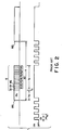
- each of the pager signals RS is a POCSAG code signal which is set up in CCIR recommendation 584.
- the pager signals RS are intermittently transmitted by a base station (later shown). Generally, a time interval T between the pager signals RS is variable.
- Each of the pager signals RS carries a preamble signal PA and a batch B succeeding the preamble signal PA.
- the preamble signal PA has a preamble duration Tp equal to, for example, an eighteen-code word length when a unit codeword consists of, for example, 32 bits.
- the preamble signal PA is specified by a repetition of pulses which are of logic "1" and "0" levels.
- the batch B consists of, for example, seventeen codewords. Other batches may succeed the illustrated batch B within the time interval T although only one combination of the preamble signal PA and the batch B is depicted in the time interval T.
- the batch B comprises a frame synchronization signal SS and first through eighth frames F1 to F8.
- the frame synchronization signal SS succeeds the preamble signal PA.
- the frame synchronization signal SS has a synchronization duration Ts equal to, for example, a one-codeword length and is specified by a predetermined pattern of bits.
- the first through the eighth frames F1 to F8 successively succeed the synchronization signal SS.
- Each of first through the eighth frames F1 to F8 has a two codeword length.
- the first through the eighth frames F1 to F8 consist of first through eighth call number signals and first through eighth message signals.
- the first through the eighth call number signals are different from each other and may be grouped into first through eighth groups.
- the first through eighth groups are assigned to the first through the eighth frames F1 to F8, respectively.
- the first call number signal and the first message signal are symbolized typically at CN and ME, respectively.
- Each of the first through the eighth call number signals and the first through the eighth message signals has a one-codeword length.
- the first through the eighth frames F1 to F8 will collectively be called an address signal which is depicted at AS.
- the address signal AS has an address signal end and an address duration ending at the address signal end.
- the preamble signal PA has a preamble duration depicted at Tp.
- the synchronization and the address signals SS and AS have a synchronization duration and an address duration depicted at Ts and Ta, respectively.
- a sum of the preamble, the synchronization, and the address durations is shorter than the time interval T.
- the controller 25 puts the battery saving switch 23 in the on state during a first time duration D1 in a time period Tt and repeatedly at the time period Tt to make the receiving circuit 22 receive at least a portion of the preamble signal PA.
- the controller 25 carries out detection of the preamble signal PA.
- the operation is called a sampling operation.
- the controller 25 keeps the on state of the battery saving switch 23 until detection of the address signal end.
- the controller 25 puts the battery saving switch 23 in the off state and then returns to the sampling operation. Namely, the controller 25 puts the battery saving switch 23 in the on state repeatedly at the time period Tt to make the receiving circuit 22 receive a portion of a next one of the paging signals RS.
- the sampling operation is repeated between the pager signals RS.
- a pager receiver according to a first embodiment of this invention is similar to. that illustrated in Fig. 1 and comprises similar parts designated by like reference numerals.
- a controller 30 carries out the address decision operation in the manner mentioned above.
- the controller 30 comprises a read only memory (not shown) memorizing a battery saving operation program for carrying out the battery saving operation and comprises a random access memory (not shown).
- the controller 30 carries out time count operation as will later be described.
- the pager receiver 20 receives first through N-th pager signals successively at a first predetermined time period T1 when the power switch SW is turned from the off state to the on state.
- the first and the second pager signals are indicated at RS1 and RS2 along a top line of Fig. 4.
- the first pager signal RS1 comprises a first preamble signal depicted at PA1, a first synchronization signal depicted at SS1, and a first address signal depicted at AS1.
- the second pager signal RS2 comprises a second preamble signal depicted at PA2, a second synchronization signal depicted at SS2, and a second address signal depicted at AS2.
- each of the first and the second preamble signals PA1 and PA2 has the preamble duration Tp.
- Each of the first and the second synchronization signals SS1 and SS2 has the synchronization duration Ts.
- the first and the second address signals AS1 and AS2 consist of a single batch and two batches, respectively.
- the first address signal AS1 has a first address duration Ta1 and the address signal end depicted by a right-most vertical line outlining the address signal AS1.
- the second address signal AS2 has a second address duration Ta2 equal to twice the first address duration Ta1.
- the controller 30 carries out sampling operation from a time instant at which the power switch SW is closed. Namely, the controller 30 puts the battery saving switch 23 in the on state during the first time duration D1 in a second predetermined time period T2 and repeatedly at the second predetermined period T2 to make the receiving circuit 22 receive at least a portion of the first preamble signal PA1.
- the controller 30 can detect the first preamble signal PA1.
- the controller 30 keeps the battery saving switch 23 in the on state during a second time duration and detects the first synchronization signal SS1.
- the second time duration is illustrated along a fourth line of Fig. 4 at D2 and is longer than the synchronization duration Ts.
- the second time duration may be called a prescribed duration.
- the controller 30 keeps the switch 23 in the on state until detection of the address signal end of the first address signal AS1. On detection of the address signal end, the controller 30 puts the battery saving switch 23 in the off state until lapse of a preselected time duration from detection of the first synchronization signal SS1.
- the preselected time duration will be called a third time duration.
- the third time duration is illustrated along the fourth line at D3 and is shorter than the first predetermined time period T1. More specifically, the third time duration D3 is represented by an equation given by: D3 ⁇ T1 - (Tp - Ts/2).
- the controller 30 puts the battery saving switch 23 in the on state during the first tine duration D1 to make the receiving circuit 22 receive a part of the second preamble signal PA2.
- the controller 30 detects the second preamble signal PA2
- the controller 30 keeps the on State during the second time duration D2 and detects whether or not the second synchronization signal SS2 is detected within the second time duration D2.
- the controller 30 keeps the switch 23 in the on state until detection of the address signal end of the second address signal AS2.
- the controller 30 puts the battery saving switch 23 in the off-state until lapse of the third time duration D3 from detection of the second synchronization signal SS2.
- the battery saving operation starts when the power switch SW is turned from the off state to the on state.
- the controller 30 puts the battery saving switch 23 in the off state during a fourth time duration D4 which is equal to an algebraic sum of the second predetermined time period T2 minus the first time duration D1.
- the controller 30 puts the battery saving switch 23 in the on state during the first time duration D1 immediately following the fourth time duration D4.
- the controller 30 judges whether or not the first preamble signal PA1 is detected within the first time duration D1. If the first preamble signal PA1 is not detected within the first time duration D1, operation turns back to the second stage S2. When the first preamble signal PA1 is detected within the first time duration D1, operation proceeds to a fifth stage S5.
- the second through the fourth stages S2 to S4 are for putting the battery saving switch 23 in the on state repeatedly at the second predetermined time period T2 to make the receiving circuit 22 receive at least the above-mentioned portion of the preamble signal of the first pager signal and produce a first preamble detection signal.
- the second through the fourth stages S2 to S4 are for carrying out the sampling operation and may collectively be called a first partial switch operating unit.
- the controller 30 keeps the switch 23 in the on state during the second time duration D2 immediately following the first time duration D1.
- the controller 30 decides whether or not the first synchronization signal SS1 is detected within the second time duration D2. When the first synchronization signal SS1 is not detected within the second time duration D2, operation turns back to the second stage S2. If the first synchronization signal SS1 is detected within the second time duration D2, operation proceeds to a seventh stage S7.
- the fifth and the sixth stages S5 and S6 are for putting the switch 23 in the on state during the second time duration D2 from production of the first preamble detection signal and for producing a first synchronization detection signal.
- the fifth and the sixth stages S5 and S6 may collectively be called a second partial switch operating unit.
- the controller 30 starts the time count operation of the third time duration D3.
- the seventh stage S7 may be called a timer.
- the controller 30 starts reception operation of the first address signal AS1.
- the controller 30 determines whether or not the first address signal AS1 is present. In other words, the controller 30 detects the address signal end of the first address signal AS1. If the first address signal AS1 is present, operation turns back to the eighth stage S8. When either the first address signal AS1 is absent or the controller 30 detects the address signal end of the first address signals AS1, the controller 30 puts the switch 23 in the off state. Thus, operation proceeds to a tenth stage S10.
- the eighth and the ninth stages S8 and S9 are for putting the battery saving switch 23 in the on state to make the receiving circuit 22 receive the address signal AS1 of the first pager signal RS1, detect the address signal end of the first pager signal, and produce a first and detection signal.
- the eighth and the ninth stages S8 and S9 may collectively be called a third partial switch operating unit.
- the controller 20 keeps the off state of the battery saving switch 23 until an end of the third time duration D3.
- the tenth stage S10 is for keeping the switch 23 in the off state from reception of the first end detection signal until lapse of the third time duration T3 which is timed by using the first synchronization detection signal.
- the tenth stages S10 may be called a fourth partial switch operating unit.
- the controller 30 puts the switch 23 in the on state during the first time duration D1 immediately following the third time duration D3.
- the controller 30 decides whether or not the second preamble signal PA2 is detected within the first time duration D1. When the second preamble signal PA2 is not detected, operation turns back to the second stage S2. If the second preamble signal PA2 is detected, operation proceeds to a thirteenth stage S13.
- the eleventh and the twelfth stages S11 and S12 are for putting the switch 23 in the on state during the first time duration D1 to make the receiving circuit 22 receive at least a part of the preamble signal of each pager signal of the second through the N-th pager signals and produce a second preamble detection signal.
- the eleventh and the twelfth stages S11 and S12 may collectively be called a fifth partial switch operating unit.
- the controller 30 keeps the switch 23 in the on state during the second time duration D2.
- the controller 30 decides whether or not the second synchronization signal SS2 is detected within the second time duration D2.
- operation turns back to the eighth stage S8.
- the thirteenth and the fourteenth stages S13 and S14 are for putting the switch 23 in the on state during the second time duration D2 from reception of the second preamble detection signal to make the receiving circuit 22 receive whole of the synchronization and the address signals of the each pager signal and produce a second synchronization detection signal and a second end detection signal.
- the thirteenth and the fourteenth stages S13 and S14 may collectively be called a sixth partial switch operating unit.
- the controller 30 starts reception operation of the second address signal AS2.
- the controller 30 decides whether or not the second address signal AS2 is present. If the second address signal AS2 is present, operation turns back to the eighth stage S8. When the second address signal AS2 is absent, the controller 30 puts the switch 23 in the off state. Then, operation proceeds again to the tenth stage S10.
- the tenth stage S10 is for keeping the switch 23 in the off state from production of the second end detection signal until lapse of the third time duration D3 which is timed by using the second synchronization detection signal. In this stage of operation, the tenth stage S10 may be referred to afresh as a seventh partial switch operating unit.
- the controller 30 puts the switch 23 in the on state during the first time duration D1.
- the controller 30 judges whether or not the third preamble signal is detected within the first time duration D1. If the third preamble signal is not detected within the first time duration D1, operation turns back to the second stage S2. When the third preamble signal is detected within the first time duration D1, operation proceeds again to the fifth stage S5.
- the second through the fourth stages S2 to S4 are for putting the switch 23 in the on state repeatedly at the second predetermined time period T2 if no preamble signal is received when the battery saving switch 23 is put intermittently in the on state during the first time duration D1.
- the second through the fourth stages S2 to S4 may collectively be referred to anew as an eighth partial switch operating unit.
- the pager receiver has an excellent battery saving efficiency because the useless sampling operation is reduced. It should be noted here that the battery saving efficiency becomes higher in proportion to an increment of the first predetermined time period T1. Furthermore, the battery saving operation is useful when a small number of calls is given to the pager receiver 20.
- the other battery saving operation is similar to that illustrated in Fig. 5 except that a fifteenth through eighteenth stages S15 to S18 are substituted between the third and the sixth stages S3 and S6 for the fourth and the fifth stages S4 and S5 and a nineteenth stage S19 is added between the ninth and the tenth stages S9 and S10.
- the random access memory has a flag code area (not shown) for memorizing a specific flag code as will shortly be described.
- the controller 30 puts the battery saving switch 23 in the on state during the first time duration D1.
- the controller 30 decides whether or not the receiving circuit 22 receives a radio signal which may carry the pager signals. When the receiving circuit 22 does not receive the radio signal, operation turns back to the second stage S2. If the receiving circuit 22 receives the radio signal as a reception radio signal, operation proceeds to a sixteenth stage S16.
- the controller 30 judges whether or not the reception radio signal is the preamble signal. If the reception radio signal is the preamble signal, operation proceeds to a seventeenth stage S17. When the reception radio signal is not the preamble signal, operation proceeds to the eighteenth stage S18.
- the controller 30 sets a preamble detection code represented by logic "1" level, as the specific flag code, in the flag code area. Subsequently, operation proceeds to the eighteenth stage S18.
- the controller 30 erases the preamble detection code of the flag code area.
- the controller 30 decides whether or not the preamble detection code is set in the flag code area.
- operation turns back to the second stage S2. If the preamble detection code is set in the flag code area, operation proceeds to the tenth stage S10. Thereafter, the tenth through the fourteenth stages S10 to S14 are successively carried out as described in conjunction with Fig. 5.
- the control station comprises a processing unit 40 between a telephone network 41 and a base station 42.
- the processing unit 40 is supplied with call information from the telephone network 41 and processes the call information into processed signals.
- the base station 42 is for successively transmitting the processed signals as the pager signals carried by a radio signal.
- the call information may comprise a call number signal and a message signal.
- the call number signal represents a call number.
- the message signal represents a message.
- the processing unit 40 comprises an input section 43 for receiving the call information.
- a queuing buffer memory 44 is for memorizing the call information as memorized information.
- An information processor 45 is for processing the memorized information into processed information.
- a controller 46 is for controlling the input section 43, the queuing buffer memory 44, and the information processor 45.
- the processing unit 40 further comprises a subscriber file memory 47 preliminarily memorizing a plurality of subscriber numbers, and a timer 48 for timing a preamble duration, a synchronization duration, and an address including duration successively in a predetermined time period T to produce a time-out signal.
- the address including duration is what should be referred to more exactly as an address signal including duration.
- the information processor 45 comprises a signal generating unit 49 for generating 6 preamble signal having a first duration and a synchronization signal having a second duration and a partial processor 50 for processing the memorized information into address signals.
- Each of the address signals has a variable duration as an address duration which immediately follows the synchronization duration and is shorter than the address including duration.
- the first and the second durations are equal to the preamble and the synchronization durations described in conjunction with Fig. 2, respectively.
- the queuing buffer memory 44 comprises first through third queuing memory areas QM1, QM2, and QM3 and a transferring memory ares TM.
- Each of the first through the third queuing memory areas QM1 to QM3 and the transferring memory area TM has a memory capacity capable of memorizing a maximum number of batches which can be produced within the first predetermined time period T1.
- the queuing buffer memory 44 further comprises a flag memory area (not shown) for memorizing a flag code for indicating whether the queuing buffer memory 44 is full or vacant. The flag code is set in a busy state by a logic "1" level when all of the first through the third queuing memory areas QM1 to QM3 and the transferring memory area TM are full.
- reception operation is carried out by the controller 46 in cooperation with the input section 43 and the queuing buffer memory 44.
- the controller 46 detects whether or not the flag code indicates the busy state. When the flag code indicates the busy state, the first stage ST1 is repeated. If the flag code does not indicate the busy state but the vacant state, operation proceeds to a second stage ST2.
- the controller 46 detects whether or not a call is represented by the call information. When the call is absent, operation turns back to the first stage ST1. If the call is present, operation proceeds to a third stage ST3.
- the input section 43 receives the call information as reception call information.
- the controller 46 receives the call number of the reception call information as a received call number and decides whether or not the received call number is memorized in the subscriber file memory 47.
- the received call number is not memorized in the subscriber file memory 47, operation proceeds to a fifth stage ST5. If the received call number is memorized in the subscriber file memory 47, operation proceeds to a sixth stage ST6.
- the controller 46 controls the input section 43 to make the input section 43 supply an invalid tone signal back to the telephone network 41.
- the invalid tone signal is for informing that the call is invalid.
- the telephone network 41 delivers an invalid tone to a subscriber (not shown) in the manner known in the art. Subsequently, operation turns back to the first stage ST1. This means that the call is rejected.
- the controller 46 receives the message signal of the call information as a received message signal.
- the controller 46 decides whether or not the first queuing memory area QM1 has a vacant area. If the first queuing memory area QM1 has the vacant area, operation proceeds to an eighth stage ST8. When the first queuing memory area QM1 has no vacant area, namely, the first queuing memory area QM1 is full, operation proceeds to a ninth stage ST9.
- the controller 46 stores the received call number and the received message signal in the first queuing memory area QM1. Subsequently, operation turns back to the first stage ST1.
- the controller 46 decides whether or not the second queuing memory area QM2 has a vacant area. If the second queuing memory area QM2 has the vacant area, operation proceeds to a tenth stage ST10. When the second queuing memory area QM2 has no vacant area, operation proceeds to an eleventh stage ST11. When the second queuing memory area QM2 is full, the control station may be regarded as being in a congestion state of calls. In this event, if the controller 46 accepts a new call, the control station falls into a degraded service. Accordingly, the new call should be rejected as will shortly be described.
- the controller 46 stores the received call number and the received message signal in the second queuing memory area QM2. Subsequently, operation turns back to the first stage ST1.
- the controller 46 sets the flag code in the busy state. As a result, the new call is rejected at the first stage ST1.
- the controller 46 decides whether or not the third queuing memory area QM3 has a vacant area, If the third queuing memory area QM3 has the vacant area, operation proceeds to a thirteenth stage ST13. When the third queuing memory area QM3 has no vacant area, operation proceeds to a fourteenth stage ST14.
- the controller 46 stores the received call number and the received message signal into the third queuing memory area QM3. Subsequently, operation turns back to the first stage ST1.
- the controller 46 controls the input section 43 to make the input section 43 supply the invalid tone signal to the telephone network 41 as mentioned before. In this event, the call is rejected. Then, operation turns back to the first stage ST1.
- Fig. 9 With reference to Fig. 7 continued, the description will proceed to output operation of the processed signal.
- the output operation is carried out by the controller 46 in cooperation with the queuing buffer memory 44, the information processor 45 and the timer 48. Let each of the first through the third queuing memory areas QM1 to QM3 already memorize first through third memorized information, respectively. Similarly, the transferring memory area TM already memorizes a fourth memorized information.
- the controller 46 detects whether or not the timer 48 produces the time-out signal. When the timer 48 does not yet produce the time-out signal, the first stage SS1 is repeated. If the timer 48 produces the time-out signal, operation proceeds to a second stage SS2.
- the controller 46 shifts the first memorized information from the first queuing memory area QM1 to the transferring memory area TM and shifts the fourth memorized information from the transferring memory area TM back to the third queuing memory area QM3. Similarly, the controller 46 shifts the third memorized information from the third queuing memory area QM3 to the second queuing memory area QM2 and the second memorized information from the second queuing memory area QM2 to the first queuing memory area QM1. As a result, the first through the third queuing memory areas QM1 to QM3 memorize the fourth, the third, and the second memorized information as first through third shifted information, respectively. Similarly, the transferring memory area TM memorizes the first memorized information as fourth shifted information.
- the controller 46 decides whether or not the transferring memory area TM memorizes at least one of the call number and the message signal. If the transferring memory area TM memorizes the fourth shifted information comprising one of the call number and the message signal, operation proceeds to a fourth stage SS4. When the transferring memory area TM memorizes none of the call number and the message signal, operation proceeds to a fifth stage SS5.
- the third stage SS3 is for detecting repeatedly at the predetermined period T whether or not the call information is memorized in the transferring memory area TM to produce an empty detection signal while the transferring memory area TM memcrizes none of the call number and the message signal. Therefore, the third stage SS3 may be called a detecting unit.
- the queuing buffer memory 44 transfers the fourth shifted information from the transferring memory area TM to the partial processor 50.
- the partial processor 50 processes the fourth shifted information into one of the address signals.
- the partial processor 50 is supplied with the preamble and the synchronization signals from the signal generating unit 49.
- the controller 46 controls the partial processor 50 to make the partial processor 50 consecutively transmit the preamble and the synchronization signals and one of the address signals to the base station 42 in the preamble, the synchronization, and the address including durations collectively as one of the processed signals.
- the controller 46 erases the fourth shifted information memorized in the transferring memory area TM.
- the controller 46 resets the busy state in the flag memory area. Subsequently, operation turns back to the first stage SS1.
- the signal generating unit 49 supplies the preamble and the synchronization signals to the partial processor 50.
- the controller 46 controls the partial processor 50 to make the partial processor 50 consecutively transmit, during presence of the empty detection signal, the preamble signal, the synchronization signal, and no signal to the base station 42 in the preamble, the synchronization, and the address including durations collectively as a dummy signal rather than as one of the processed signals.
- the dummy signal will later be taken into account.
- operation turns back to the first stage SS1.
- the eighth stage SS8 may be called a partial control unit.
- control station can produce the processed signals at the first predetermined time period T1 regardless of the congestion state of calls. Furthermore, the control station can produce the processed signals successively at the first predetermined time period T1 without interruption even when the control station is supplied with no call information.
- a pager receiver is similar in structure to the pager receiver illustrated in Fig. 3.
- the pager receiver is said to be according to the second embodiment of this invention.
- the controller 30 operates in a following manner.
- each of the first through the N-th pager signals comprise the preamble signal PA having the preamble duration and the batch B which is described above.
- the batch B comprises the synchronization signal SS succeeding the preamble signal PA and having the synchronization duration and the address signal AS succeeding the synchronization signal SS and having the address signal end and the address duration ending at the address signal end.
- a sum of the preamble, the synchronization, and the address durations is not longer than the predetermined time period T.
- the power switch SW is turned from the off state to the on state.
- the preparing operation is for determining the predetermined time period T to prepare the receiving circuit 22 for its operation by putting the battery saving switch 23 in the on state to make the receiving circuit 22 receive the synchronization signals of the first through the (L-1)-th pager signals as received signals and detect the address signal end of the (L-1)-th pager signal and to use the received signals in determining the predetermined time period T.
- the controller 30 starts time count operation of a first time interval from reception of the synchronization signal of the (L-1)-th pager signal.
- the first time interval is depicted at t01 along a second line of Fig. 10.
- the controller 30 decides whether or not the address signal of the (L-1)-th pager signal is present. In other words, the controller 30 detects the address signal end of the (L-1)-th pager signal. If the address signal is present, the fourth stage SP4 is repeated. When either the address signal is absent or the controller 30 detects the addess signal end of the (L-1)-th pager signal, operation proceeds to a fifth stage SP5.
- the controller 30 puts the battery saving switch 23 in the off state.
- the controller 30 decides whether or not the first time interval t01 is over. When the first time interval t01 does not elapse, the sixth stage SP6 is repeated. If the first time interval t01 is over, operation proceeds to a seventh stage SP7.
- the controller 30 puts the switch 23 in the on state and starts time count operation of a second time interval.
- the second time interval is depicted at t02 along the second line of Fig. 10.
- the second time interval t02 is, for example, 0.125 second long.
- the first time interval t01 is equal to an algebraic sum of the predetermined period T minus the second time interval t02.
- the second time interval t02 is longer than the synchronization duration and shorter than twice the synchronization duration.
- the controller 30 decides whether or not the second time interval t02 is over. If the second time interval t02 is over, operation turns back to the second stage SP2. When the second time interval does not elapse, operation proceeds to a ninth stage SP9.
- the controller 30 decides whether or not the receiving circuit 22 receives the synchronization signal of the L-th pager signal within the second time interval t02.
- the receiving circuit 22 does not receive the synchronization signal of the L-th pager signal within the second time interval
- operation turns back to the eighth stage SP8.
- the receiving circuit 22 receives the synchronization signal
- operation turns back to the third stage SP3.
- the third through the ninth stages SP3 to SP9 are for carrying out the battery saving operation.
- the battery saving switch 23 is put in the on state during the second time interval t02 immediately following the first time interval t01 to make the receiving circuit 22 receive the synchronization and the address signals of each signal of the L-th through the N-th pager signals and detect the address signal end of each signal. Furthermore, the battery saving switch 23 is put in the off state from detection of the address signal end of the each signal until lapse of the second time interval t02 from reception of the synchronization signal of each signal.
- the third through the ninth stages SP3 to SP9 may collectively be called a switch operating unit.
- the controller 30 repeats period determining operation (L - 2) times by detecting the synchronization signal of the first through the (L-1)-th pager signals.
- the predetermined period T is determined by detecting an interval between one of the synchronization signal and a next one of the synchronization signal. Therefore, the period determining operation starts from reception of the synchronization signal of the second pager signal.
- the controller 30 counts the number of the period determining operations as a counted value.
- the controller 30 starts the period determining operation.
- the controller 30 sets the counted value at zero.
- the controller 30 decides whether or not the preamble signal of the second pager signal is received. When the preamble signal is not received, the third stage SG3 is repeated. If the preamble signal is received, operation proceeds to a fourth stage SG4.
- the controller 30 decides whether or not the synchronization signal of the second pager signal is received. When the synchronization signal is not received, operation turns back to the second stage SG2. If the synchronization signal is received, operation proceeds to a fifth stage SG5.
- the controller 30 determines the predetermined period T, as a first determined period, by detecting the interval between the synchronization signals of the first and the second pager signals.
- the controller 30 stores the first determined period in the random access memory mentioned before. Simultaneously, the controller 30 counts up the counted value to one.
- the controller 30 decides whether or not the counted value is equal to one. When the counted value is not equal to one, operation proceeds to a seventh stage SG7. If the counted value is equal to one, operation proceeds to an eighth stage SG8. At this moment, operation proceeds to the eighth stage SG8 because the counted value is equal to one.
- the controller 30 decides whether or not the address signal of the second pager signal is present. If the address signal is present, the eighth stage SG8 is repeated. When the address signal is absent, operation turns back to the third stage SG3.
- the controller 30 decides whether or not the preamble signal of the third pager signal is received. When the preamble signal is not received, the third stage SG3 is repeated. If the preamble signal is received, operation proceeds to the fourth stage SG4.
- the controller 30 decides whether or not the synchronization signal of the third pager signal is received. When the synchronization signal is not received, operation turns back to the second stage SG2. If the synchronization signal is received, operation proceeds to the fifth stage SG5.
- the controller 30 determines the predetermined period T, as a second determined period, by detecting the interval between the synchronization signals of the second and the third pager signals.
- the controller 30 stores the second determined period in the random access memory. Simultaneously, the controller 30 changes the counted value to two.
- the controller 30 decides whether or not the counted value is equal to one. When the counted value is not equal to one, operation proceeds to the seventh stage SG7. If the counted value is equal to one, operation proceeds to the eighth stage SG8. At this moment, operation proceeds to the seventh stage SG7 because the counted value is equal to two.
- the controller 30 calculates a first difference between the first and the second determined periods.
- the controller 30 decides whether or not the first difference is less than a predetermined value. When the first difference is less than the predetermined value, operation proceeds to a tenth stage SG10. If the first difference is not less than the predetermined value, operation proceeds to an eleventh stage SG11.
- the controller 30 stores the second determined period in the random access memory as a previously determined period. This means that the second determined period is stored in the random access memory in place of the first determined period. Simultaneously, the controller 30 changes the counted value to three. Then, operation proceeds to the eighth stage SG8.
- the controller 30 decides whether or not the period determining operation is repeated (L - 1) times. When the number of the period determining operations, does not reach the (L - 1) times, operation proceeds to the eleventh stage SG11. If the period determining operation is repeated the (t - 1) times, operation proceeds to a twelfth stage SG12.
- the controller 30 calculates an arithmetic mean value of the first through an (L - 1)-th determined periods.
- the preparing operation comes to an end.
- the control station 60 comprises an active and a backup control units 61 and 62 each of which is similar in structure and operation to each other,
- the control station 60 further comprises an active and a backup processing circuits 63 and 64.
- Each of the active and the backup processing circuits 63 and 64 is similar in structure and operation to each other.
- Each of the active and the backup control units 61 and 62 is connected to a telephone network 65 through a plurality of input trunks 66 and supplied with the call information from the telephone network 65.
- the control units 61 and 62 may collectively be called a control unit depending on the circumstances.
- Each of the active and the backup processing circuits 63 and 64 is connected to first through M-th output trunks 67-1 to 67-M.
- the first through the M-th output trunks 67-1 to 67-M are connected to first through M-th base stations 68-1 to 68-M, respectively, which have first through M-th service areas 69-1 to 69-M, respectively.
- Each of the active and the backup processing circuits 63 and 64 is for processing the call information into processed signals successively at the predetermined time period T to make the first through the M-th base stations 68-1 to 68-M transmit the processed signals as the pager signals.
- the control station further comprises a signal generating unit 71 for generating an instruction signal.
- the instruction signal is indicated at IS along a first line.
- the instruction signal is for putting a selected one of the active and the backup processing circuits 63 and 64 into operation.
- the active control unit 61 puts the active processing circuit 63 into operation of producing the processed signals while the backup control unit 62 puts the back-up processing circuit 64 out of operation of producing the processed signals.
- the instruction signal is absent, the active control unit 61 puts the active processing circuit 63 out of operation of producing the processed signals while the backup control unit 62 puts the back-up processing circuit 64 into operation of producing the processed signals.
- the predetermined time period T repeatedly follows one after another as a succession of predetermined time periods.
- the active processing circuit 63 is put into operation upon start of one of the predetermined periods that starts in the succession earliest after appearance of the instruction signal IS.
- the backup processing circuit 64 is put into operation upon start of one of the predetermined periods that start, in the succession earliest after disappearance of the instruction signal IS.
- the active control unit 61 When supplied with the call information, the active control unit 61 carries out collation operation, such as a subscriber collation and a service menu collation, in the manner known in the art. After the collation operation, the active control unit 61 supplies the call information to the active processing circuit 63 and controls the active processing circuit 63. Supplied with the call information, the active processing circuit 63 processes the call information into processed signals in the manner described in conjunction with Fig. 7.
- the processing circuit 63 delivers the processed signals successively at the predetermined time period T to the first through the M-th base stations 68-1 to 68-M through the first through the M-th output trunks 67-1 to 67-M.
- the first through the M-th base stations 68-1 to 68-M transmit the processed signals as the pager signals through first through M-th transmitting antennas 70-1 to 70-M, respectively.
- the control station 60 further comprises a change signal generating unit 72 for generating a change indication signal.
- the control station 60 further comprises a timer 73 for timing the predetermined time period T to make each of the active and the backup control units 61 and 62 put each of the active and the backup processing circuits 63 and 64 into operation at the predetermined period T.
- the timer 73 changes the predetermined time period T to a prescribed time period T' when supplied with the change indication signal. From disappearance of the change indication signal, each of the active and the backup control units 61 and 62 puts the active and the backup processing circuits 63 and 64 into operation of producing the processed signals successively at the prescribed time period T' when the prescribed time period T' starts earliest from disappearance of the change indication signal.
- the predetermined period repeatedly follows one after another as a succession of predetermined time periods.
- Each of the active and the backup processing circuits 63 and 64 is put into operation upon start of one of the predetermined periods that starts in the succession earliest after disappearance of the change indication signal.
- the prescribed time period T' should be longer than the second time interval t02 to make the pager receiver detect the synchronization signal as described in conjunction with Figs. 10 and 11.
- the timer 73 may count a time period longer than the predetermined time period T in place of the predetermined time period T.
- the backup control unit 62 decides whether or not the control operation is operable. When the control operation is not operable, the second stage SE2 is repeated. If the control operation is operable, operation proceeds to a third stage SE3.
- the backup control unit 62 resets operation of the backup processing circuit 64 and resets the timer 73.
- the backup control unit 62 decides whether or not the timer 73 counts up the predetermined time period T. If the timer 73 does not count up the predetermined time period T, the fourth stage SE4 is repeated. When the timer 73 counts up the predetermined time period T, operation proceeds to a fifth stage SE5.
- the backup control unit 62 decides whether or not the change indication signal is generated. When the change indication signal is generated, operation proceeds to a sixth stage SE6. If the change indication signal is not generated, operation proceeds to a seventh stage SE7.
- the backup control unit 62 again resets the timer 73.
- the backup control unit 62 controls the backup processing circuit 64 to make the backup processing circuit 64 produce one of the processed signals. Then, operation turns back to the fourth stage SE4. Thereafter, the fourth through the eighth stages SE4 to SE8 are repeated.
- the timer 73 changes the predetermined time period T to the prescribed time period T'.
- the backup control unit 62 decides whether or not the timer 73 counts up the prescribed time period T'. If the timer 73 does not count up the prescribed time period T', the ninth stage SE9 is repeated. When the timer 73 counts up the prescribed time period T', operation proceeds again to the seventh stage SE7.
- the backup control unit 64 resets the timer 73.
- the backup control unit 62 controls the backup processing circuit 64 to make the backup processing circuit 64 produce one of the processed signals. Then, operation turns back to the fourth stage SE4. Thereafter, the fourth through the eighth stages SE4 to SE8 are repeated.
- the pager signals can be received correctly by the pager receiver described in conjunction with Figs. 10 and 11.
- the pager receiver can receive the pager signals without error even when one of the active and the backup processing circuits 63 and 64 is changed to another one of the active and the backup processing circuits 63 and 64 and even when the timer 73 changes one of the predetermined and the prescribed time periods T and T' to another one of the predetermined and the prescribed time periods T and T'.
- the pager receiver 20 should be put into operation with the prescribed period T' used either as the first predetermined time period T1 or as the predetermined time period T.
- the timer 48 may be included in the controller 46.
- the timer 73 may be included in the active and the backup control units 61 and 62.
Claims (7)
- Procédé comprenant les étapes de transmission et de réception d'informations d'appel en tant que signaux d'adresse dans des premier et deuxième à N-ième signaux d'appel disposés successivement à une première période prédéterminée T1, où N représente un nombre entier qui n'est pas inférieur à deux, chacun desdits signaux d'adresse ayant une fin de signal et une durée d'adresse Ta1 finissant à ladite fin de signal,ladite étape de transmission comprenant les sous-étapes consistant à :- disposer consécutivement dans ladite première période prédéterminée T1 une durée de préambule Tp, une durée de synchronisation Ts, et une durée d'inclusion d'adresse qui est supérieure à ladite durée d'adresse Ta1;- générer un signal de préambule ayant ladite durée de préambule Tp et un signal de synchronisation ayant ladite durée de synchronisation Ts; et- disposer lesdits signaux de préambule et de synchronisation et chacun desdits signaux d'adresse consécutivement dans lesdites durées de préambule, de synchronisation et d'inclusion d'adresse collectivement en tant que chacun desdits signaux d'appel;ladite étape de réception comprenant les sous-étapes consistant à :- placer un commutateur de sauvegarde de batterie dans un état passant de façon répétitive à une seconde période prédéterminée T2 plus courte que ladite durée de préambule Tp, pour permettre à un circuit récepteur de recevoir au moins une partie du signal de préambule dudit premier signal d'appel;- conserver ledit commutateur de sauvegarde de batterie dans ledit état passant durant une durée prescrite D2, après la réception de ladite partie, pour permettre audit circuit récepteur de détecter le signal de synchronisation dudit premier signal d'appel;- chronométrer une durée présélectionnée D3 à partir de la détection dudit signal de synchronisation, dans laquelle D3 = T1 - (Tp - TS/2);- placer ledit commutateur de sauvegarde de batterie dans un état bloqué à partir de la détection de la fin de signal du signal d'adresse dudit premier signal d'appel jusqu'à l'écoulement de ladite durée présélectionnée D3 à partir de la détection du signal de synchronisation dudit premier signal d'appel, pour que le commutateur de sauvegarde de batterie (23) reste dans l'état bloqué pour chaque période entre la réception des signaux d'appel;- placer ledit commutateur de sauvegarde de batterie momentanément dans ledit état passant après l'écoulement de ladite durée présélectionnée D3, pour permettre audit circuit récepteur de recevoir au moins une partie de chaque signal desdits deuxième à N-ième signaux d'appel;- conserver ledit commutateur de sauvegarde de batterie dans ledit état passant, après la réception de ladite au moins une partie, pour permettre audit circuit récepteur de recevoir les signaux de synchronisation et d'adresse dudit chaque signal et de détecter la fin de signal du signal d'adresse dudit chaque signal; et- placer ledit commutateur de sauvegarde de batterie dans ledit état bloqué à partir de la détection de la fin de signal du signal d'adresse dudit chaque signal jusqu'à l'écoulement de ladite durée présélectionnée D3 à partir de la détection du signal de synchronisation dudit chaque signal.
- Procédé comprenant les étapes de transmission et de réception d'informations d'appel en tant que signaux d'adresse dans des premier à (L-1)-ième et L-ième à N-ième signaux d'appel disposés successivement à une période prédéterminée T, où (L-1) représente un premier nombre entier qui n'est pas inférieur à dix environ, (N-L) représentant un deuxième nombre entier qui n'est pas inférieur à un, chacun desdits signaux d'adresse ayant une fin de signal et une durée d'adresse finissant à ladite fin de signal,
ladite étape de transmission comprenant les sous-étapes consistant à :- disposer consécutivement dans ladite période prédéterminée T une durée de préambule, une durée de synchronisation, et une durée d'inclusion d'adresse qui n'est pas plus courte que ladite durée d'adresse;- générer un signal de préambule ayant ladite durée de préambule et un signal de synchronisation ayant ladite durée de synchronisation; et- disposer lesdits signaux de préambule et de synchronisation et chacun desdits signaux d'adresse consécutivement dans lesdites durées de préambule, de synchronisation et d'inclusion d'adresse collectivement en tant que chacun desdits signaux d'appel;ladite étape de réception comprenant les sous-étapes consistant à :- placer un commutateur de sauvegarde de batterie dans un état passant pour permettre à un circuit récepteur de recevoir le signal de synchronisation de chaque signal desdits premier à (L-1)-ième signaux d'appel en tant que signaux reçus et de détecter la fin de signal du signal d'adresse dudit chaque signal, et d'utiliser lesdits signaux reçus pour déterminer une période déterminée en tant que dite période prédéterminée T;- placer ledit commutateur de sauvegarde de batterie dans un état bloqué à partir de la détection de la fin de signal du signal d'adresse dudit (L-1)-ième signal d'appel jusqu'à l'écoulement d'un premier intervalle de temps t01 à partir de la détection du signal de synchronisation dudit (L-1)-ième signal d'appel, ledit premier intervalle de temps t01 étant plus court que ladite période prédéterminée T, pour que le commutateur de sauvegarde de batterie reste dans l'état bloqué pour chaque période entre la réception des signaux d'appel;- placer ledit commutateur de sauvegarde de batterie dans ledit état passant durant un second intervalle de temps t02 suivant immédiatement ledit premier intervalle de temps t01, pour que ledit circuit récepteur reçoive les signaux de synchronisation et d'adresse de chaque signal d'appel desdits L-ième à N-ième signaux d'appel et détecte la fin de signal du signal d'adresse dudit chaque signal d'appel, ledit premier intervalle de temps t01 étant égal à une somme algébrique de ladite période prédéterminée T moins ledit second intervalle de temps t02; et- placer ledit commutateur de sauvegarde de batterie dans ledit état bloqué à partir de la détection de la fin de signal du signal d'adresse dudit chaque signal d'appel jusqu'à l'écoulement dudit premier intervalle de temps t01 à partir de la détection du signal de synchronisation de chaque signal d'appel mentionné en dernier. - Récepteur d'appel pour recevoir des premier et deuxième à N-ième signaux d'appel successivement à une première période prédéterminée T1, où N représente un nombre entier qui n'est pas inférieur à deux, chacun desdits signaux d'appel comprenant un signal de préambule ayant une durée de préambule Tp, un signal de synchronisation suivant ledit signal de préambule et ayant une durée de synchronisation Ts, et un signal d'adresse suivant ledit signal de synchronisation et ayant une fin de signal d'adresse et une durée d'adresse Tal finissant à ladite fin de signal d'adresse, une somme desdites durées de préambule, de synchronisation et d'adresse étant plus courte que ladite première période prédéterminée T1, ledit récepteur comportant un commutateur de sauvegarde de batterie ayant un état passant et un état bloqué et un circuit récepteur connecté audit commutateur de sauvegarde de batterie et validé pendant que ledit commutateur de sauvegarde de batterie est dans ledit état passant, ledit récepteur comprenant :- des moyens de fonctionnement de commutateur connectés audit circuit récepteur et audit commutateur de sauvegarde de batterie pour placer ledit commutateur de sauvegarde de batterie dans ledit état passant de façon répétitive à une seconde période prédéterminée T2 plus courte que ladite durée de préambule Tp, pour que ledit circuit récepteur reçoive au moins une partie du signal de préambule et la totalité des signaux de synchronisation et d'adresse dudit premier signal d'appel et détecte la fin de signal d'adresse dudit premier signal d'appel, lesdits moyens de fonctionnement de commutateur conservant ledit commutateur de sauvegarde de batterie dans ledit état passant pour que ledit circuit récepteur reçoive au moins une partie du signal de préambule et la totalité des signaux de synchronisation et d'adresse de chacun desdits deuxième à N-ième signaux d'appel et détecte ladite fin de signal d'adresse de chacun desdits deuxième à N-ième signaux d'appel, lesdits moyens de fonctionnement de commutateur plaçant ledit commutateur de sauvegarde de batterie dans ledit état bloqué à partir de la détection de la fin de signal d'adresse de chaque signal desdits premier à N-ième signaux d'appel jusqu' à l'écoulement d'une durée présélectionnée D3 à partir de la détection du signal de synchronisation dudit chaque signal pour que le commutateur de sauvegarde de batterie reste dans l'état bloqué pour chaque période entre la réception des signaux d'appel, ladite durée présélectionnée D3 étant chronométrée à partir de la détection dudit signal de synchronisation et étant donnée par :

- Récepteur d'appel selon la revendication 3, dans lequel lesdits moyens de fonctionnement de commutateur comprennent :- des premiers moyens de fonctionnement de commutateur partiel connectés audit circuit récepteur et audit commutateur de sauvegarde de batterie pour placer ledit commutateur de sauvegarde de batterie dans ledit état passant de façon répétitive à ladite deuxième période prédéterminée pour que ledit circuit récepteur reçoive au moins ladite partie du signal de préambule dudit premier signal d'appel et produise un premier signal de détection de préambule;- des deuxièmes moyens de fonctionnement de commutateur partiel connectés audit circuit récepteur, audit commutateur de sauvegarde de batterie et auxdits premiers moyens de fonctionnement de commutateur partiel pour conserver ledit commutateur de sauvegarde de batterie dans ledit état passant durant une durée prescrite D2 à partir de la production dudit premier signal de détection de préambule et produire un premier signal de détection de synchronisation, ladite durée prescrite D2 étant plus longue que ladite durée de synchronisation Ts;- des moyens d'horloge connectés auxdits deuxièmes moyens de fonctionnement de commutateur partiel pour chronométrer ladite durée présélectionnée D3 à partir d'un instant auquel ledit circuit récepteur produit un signal d'entrée d'horloge lors de la détection dudit signal de synchronisation;- des troisièmes moyens de fonctionnement de commutateur partiel connectés audit circuit récepteur, audit commutateur de sauvegarde de batterie et auxdits moyens d'horloge pour placer ledit commutateur de sauvegarde de batterie dans ledit état passant pour que ledit circuit récepteur reçoive le signal d'adresse dudit premier signal d'appel, détecte la fin de signal d'adresse dudit premier signal d'appel, et produise un premier signal de détection de fin;- des quatrièmes moyens de fonctionnement de commutateur partiel connectés audit circuit récepteur, audit commutateur de sauvegarde de batterie, auxdits moyens d'horloge et auxdits troisièmes moyens de fonctionnement de commutateur partiel pour conserver ledit commutateur de sauvegarde de batterie dans ledit état bloqué à partir de la réception dudit premier signal de détection de fin jusqu'à l'écoulement de ladite durée présélectionnée D3 qui est chronométrée en utilisant ledit premier signal de détection de synchronisation en tant que dit signal d'entrée d'horloge;- des cinquièmes moyens de fonctionnement de commutateur partiel connectés audit circuit récepteur, audit commutateur de sauvegarde de batterie et auxdits quatrièmes moyens de fonctionnement de commutateur partiel pour placer momentanément ledit commutateur de sauvegarde de batterie dans ledit état passant pour que le circuit récepteur reçoive au moins ladite partie du signal de préambule de chaque signal d'appel desdits deuxième à N-ième signaux d'appel et produise un second signal de détection de préambule;- des sixièmes moyens de fonctionnement de commutateur partiel connectés audit circuit récepteur, audit commutateur de sauvegarde de batterie et auxdits cinquièmes moyens de fonctionnement de commutateur partiel pour conserver ledit commutateur de sauvegarde de batterie dans ledit état passant durant ladite durée prescrite D2 à partir de la réception dudit second signal de détection de préambule pour que ledit circuit récepteur reçoive la totalité desdits signaux de synchronisation et d'adresse dudit chaque signal d'appel et produise un second signal de détection de synchronisation et un second signal de détection de fin;- des septièmes moyens de fonctionnement de commutateur partiel connectés audit circuit récepteur, audit commutateur de sauvegarde de batterie, auxdits moyens d'horloge et auxdits sixièmes moyens de fonctionnement de commutateur partiel pour conserver ledit commutateur de sauvegarde de batterie dans ledit état bloqué à partir de la production dudit second signal de détection de fin jusqu'à l'écoulement de la durée présélectionnée D3 qui est chronométrée en utilisant ledit second signal de détection de synchronisation en tant que dit signal d'entrée d'horloge; et- des huitièmes moyens de fonctionnement de commutateur partiel connectés audit circuit récepteur, audit commutateur de sauvegarde de batterie et auxdits cinquièmes et septièmes moyens de fonctionnement de commutateur partiel pour placer ledit commutateur de sauvegarde de batterie dans ledit état passant de façon répétitive à ladite seconde période prédéterminée T2 si aucun signal de préambule n'est reçu lorsque ledit commutateur de sauvegarde de batterie est momentanément placé dans ledit état passant.
- Récepteur d'appel pour recevoir des premier à (L-1)-ième et L-ième à N-ième signaux d'appel successivement à une période prédéterminée T, où (L-1) représente un premier nombre entier qui est inférieur à dix environ, (N-L) représentant un deuxième nombre entier qui n'est pas inférieur à un, chacun desdits premier à N-ième signaux d'appel comprenant un signal de préambule ayant une durée de préambule, un signal de synchronisation suivant ledit signal de préambule et ayant une durée de synchronisation, et un signal d'adresse suivant ledit signal de synchronisation et ayant une fin de signal d'adresse et une durée d'adresse finissant à ladite fin de signal d'adresse, une somme desdites durées de préambule, de synchronisation et d'adresse n'étant pas plus longue que ladite période prédéterminée T, ledit récepteur comportant un commutateur de sauvegarde de batterie ayant un état passant et un état bloqué et un circuit récepteur connecté audit commutateur de sauvegarde de batterie et validé pendant que ledit commutateur de sauvegarde de batterie est dans ledit état passant, ledit récepteur comprenant :- des moyens de préparation connectés audit circuit récepteur et audit commutateur de sauvegarde de batterie pour préparer ledit circuit récepteur à fonctionner en plaçant ledit commutateur de sauvegarde de batterie dans ledit état passant pour que ledit circuit récepteur reçoive les signaux de synchronisation desdits premier à (L-1)-ième signaux d'appel en tant que signaux reçus et détecte la fin de signal d'adresse dudit (L-1)-ième signal d'appel, et pour utiliser lesdits signaux reçus pour déterminer ladite période prédéterminée T, lesdits moyens de préparation plaçant ledit commutateur de sauvegarde de batterie dans ledit état bloqué à partir de la détection de la fin de signal d'adresse dudit (L-1)-ième signal d'appel jusqu'à l'écoulement d'un premier intervalle de temps t01 à partir de la détection du signal de synchronisation dudit (L-1)-ième signal d'appel, ledit premier intervalle de temps t01 étant plus court que ladite période prédéterminée T; et- des moyens de fonctionnement de commutateur connectés audit circuit récepteur, audit commutateur de sauvegarde de batterie et auxdits moyens de préparation pour placer ledit commutateur de sauvegarde de batterie dans ledit état passant durant un second intervalle de temps t02 suivant immédiatement ledit premier intervalle de temps t01, pour que ledit circuit récepteur reçoive les signaux de synchronisation et d'adresse de chaque signal desdits L-ième à N-ième signaux d'appel et détecte la fin de signal d'adresse dudit chaque signal, lesdits moyens de fonctionnement de commutateur plaçant ledit commutateur de sauvegarde de batterie dans ledit état bloqué à partir de la détection de la fin de signal d'adresse dudit chaque signal jusqu'à l'écoulement dudit premier intervalle de temps t01 à partir de la réception du signal de synchronisation dudit chaque signal pour que le commutateur de sauvegarde de batterie reste dans l'état bloqué pour chaque période entre la réception des signaux d'appel, ledit premier intervalle de temps t01 étant égal à une somme algébrique de ladite période prédéterminée T moins ledit second intervalle de temps t02.
- Récepteur d'appel selon la revendication 5, dans lequel lesdits moyens de préparation comprennent :- des premiers moyens d'horloge connectés audit circuit récepteur pour chronométrer ledit premier intervalle de temps à partir de la réception du signal de synchronisation dudit (L-1)-ième signal d'appel pour produire un premier signal d'intervalle représentatif dudit premier intervalle de temps; et- des zéroièmes moyens de fonctionnement de commutateur partiel connectés audit circuit récepteur, audit commutateur de sauvegarde de batterie et auxdits premiers moyens d'horloge pour placer ledit commutateur de sauvegarde de batterie dans ledit état passant pour que ledit circuit récepteur reçoive les signaux de synchronisation desdits premier à (L-1)-ième signaux d'appel en tant que dits signaux reçus et détecte la fin de signal d'adresse dudit (L-1)-ième signal d'appel, et pour utiliser lesdits signaux reçus pour déterminer ladite période prédéterminée, lesdits zéroièmes moyens de fonctionnement de commutateur plaçant ledit commutateur de sauvegarde de batterie dans ledit état bloqué à partir de la détection de la fin de signal d'adresse jusqu'à la disparition dudit premier intervalle de temps.
- Récepteur d'appel selon la revendication 6, dans lequel lesdits moyens de fonctionnement de commutateur comprennent :- des seconds moyens d'horloge connectés auxdits premiers moyens d'horloge pour chronométrer ledit second intervalle de temps à partir de la disparition dudit premier signal d'intervalle pour produire un second signal d'intervalle représentatif dudit second intervalle de temps;- des premiers moyens de fonctionnement de commutateur partiel connectés audit circuit récepteur, audit commutateur de sauvegarde de batterie et auxdits premiers et seconds moyens d'horloge pour placer ledit commutateur de sauvegarde de batterie dans ledit état passant durant la présence dudit second signal d'intervalle pour que ledit circuit récepteur reçoive le signal de synchronisation de chaque signal d'appel desdits L-ième à N-ième signaux d'appel et pour que lesdits premiers moyens d'horloge produisent ledit premier signal d'intervalle;- des seconds moyens de fonctionnement de commutateur partiel connectés audit circuit récepteur, audit commutateur de sauvegarde de batterie et auxdits premiers moyens de fonctionnement de commutateur partiel pour conserver ledit commutateur de sauvegarde de batterie dans ledit état passant après la réception dudit signal de synchronisation dudit chaque signal d'appel pour que ledit circuit récepteur reçoive le signal d'adresse dudit chaque signal d'appel et détecte la fin de signal d'adresse dudit chaque signal d'appel; et- des troisièmes moyens de fonctionnement de commutateur partiel connectés audit circuit récepteur, audit commutateur de sauvegarde de batterie, auxdits premiers et seconds moyens d'horloge, et auxdits seconds moyens de fonctionnement de commutateur partiel pour placer ledit commutateur de sauvegarde de batterie dans ledit état bloqué à partir de la détection de la fin de signal d'adresse dudit chaque signal d'appel jusqu'à la disparition du premier signal d'intervalle produit par la réception du signal de synchronisation dudit chaque signal d'appel et pour que lesdits seconds moyens d'horloge produisent ledit second signal d'intervalle.
Applications Claiming Priority (4)
| Application Number | Priority Date | Filing Date | Title |
|---|---|---|---|
| JP3888490 | 1990-02-19 | ||
| JP38884/90 | 1990-02-19 | ||
| JP65406/90 | 1990-03-15 | ||
| JP2065406A JP2536220B2 (ja) | 1990-03-15 | 1990-03-15 | ペ―ジングシステム |
Publications (3)
| Publication Number | Publication Date |
|---|---|
| EP0443516A2 EP0443516A2 (fr) | 1991-08-28 |
| EP0443516A3 EP0443516A3 (en) | 1992-09-02 |
| EP0443516B1 true EP0443516B1 (fr) | 1997-01-22 |
Family
ID=26378178
Family Applications (1)
| Application Number | Title | Priority Date | Filing Date |
|---|---|---|---|
| EP91102344A Expired - Lifetime EP0443516B1 (fr) | 1990-02-19 | 1991-02-19 | Transmission et réception de signaux d'appel sans opération d'échantillonnage inutile |
Country Status (6)
| Country | Link |
|---|---|
| US (1) | US5430437A (fr) |
| EP (1) | EP0443516B1 (fr) |
| AU (1) | AU636448B2 (fr) |
| CA (1) | CA2036533C (fr) |
| DE (1) | DE69124272T2 (fr) |
| HK (1) | HK1002248A1 (fr) |
Families Citing this family (14)
| Publication number | Priority date | Publication date | Assignee | Title |
|---|---|---|---|---|
| SE469254B (sv) * | 1991-10-04 | 1993-06-07 | Ericsson Telefon Ab L M | Foerfarande foer att undvika en onoedigt hoeg energifoerbrukning hos mobila stationer i ett mobiltelefonisystem |
| JP3110173B2 (ja) * | 1992-10-23 | 2000-11-20 | 日本電気株式会社 | 無線選択呼出受信機の受信制御方式 |
| GB9304638D0 (en) | 1993-03-06 | 1993-04-21 | Ncr Int Inc | Wireless data communication system having power saving function |
| USRE40032E1 (en) * | 1993-03-06 | 2008-01-22 | Agere Systems Inc. | Wireless data communication system having power saving function |
| US5745860A (en) * | 1994-12-16 | 1998-04-28 | Telefonaktiebolaget Lm Ericsson | Method and system of data transmission and reception in a mobile station within a radio telecommunications system |
| JP2922821B2 (ja) * | 1995-02-08 | 1999-07-26 | 本田技研工業株式会社 | 車両用データ処理方法および装置 |
| KR0143120B1 (ko) * | 1995-06-28 | 1998-08-01 | 김광호 | 무선호출 수신기의 전원절약방법 |
| US5821873A (en) * | 1995-07-26 | 1998-10-13 | Motorola, Inc. | Method and apparatus for saving power in a selective call receiver |
| JP3183123B2 (ja) * | 1995-08-30 | 2001-07-03 | 信越半導体株式会社 | エッチング装置 |
| US5959545A (en) * | 1996-06-14 | 1999-09-28 | Prince Corporation | Door actuated pager receiver |
| JP2877116B2 (ja) | 1996-12-26 | 1999-03-31 | 日本電気株式会社 | 無線通信システム |
| JP3886795B2 (ja) * | 2001-12-10 | 2007-02-28 | 株式会社エヌ・ティ・ティ・ドコモ | 移動通信システム、移動通信方法、移動端末及び通信基地局 |
| EP2204786A4 (fr) * | 2007-10-17 | 2013-08-21 | Hochiki Co | Système de communication |
| KR20110022438A (ko) * | 2009-08-27 | 2011-03-07 | 삼성전자주식회사 | 동기 신호 수신 장치 및 그 방법과, 이를 이용한 3d 안경의 셔터 제어 장치 및 방법 |
Family Cites Families (8)
| Publication number | Priority date | Publication date | Assignee | Title |
|---|---|---|---|---|
| GB8320979D0 (en) * | 1983-08-03 | 1983-09-07 | Multitone Electronics Plc | Decoding arrangements |
| JPS60182825A (ja) * | 1984-02-29 | 1985-09-18 | Nec Corp | 無線電話方式 |
| JPH0683090B2 (ja) * | 1986-05-16 | 1994-10-19 | アルプス電気株式会社 | 通信装置 |
| JPS6313432A (ja) * | 1986-07-03 | 1988-01-20 | Kokusai Electric Co Ltd | 選択呼出信号方式における受信装置のバツテリ・セ−ビング方法 |
| JPH01141423A (ja) * | 1987-11-28 | 1989-06-02 | Toshiba Corp | 選択呼出方式 |
| JPH01190054A (ja) * | 1988-01-25 | 1989-07-31 | Man Design Kk | 受信機 |
| CH680548A5 (fr) * | 1989-11-06 | 1992-09-15 | Koechler Erika Fa | |
| US5010330A (en) * | 1989-12-26 | 1991-04-23 | Motorola, Inc. | Paging system employing designated frame commencing information service data message transmission |
-
1991
- 1991-02-18 CA CA002036533A patent/CA2036533C/fr not_active Expired - Fee Related
- 1991-02-19 DE DE69124272T patent/DE69124272T2/de not_active Expired - Fee Related
- 1991-02-19 AU AU71208/91A patent/AU636448B2/en not_active Ceased
- 1991-02-19 EP EP91102344A patent/EP0443516B1/fr not_active Expired - Lifetime
-
1994
- 1994-06-15 US US08/261,201 patent/US5430437A/en not_active Expired - Fee Related
-
1998
- 1998-02-16 HK HK98101187A patent/HK1002248A1/xx not_active IP Right Cessation
Also Published As
| Publication number | Publication date |
|---|---|
| DE69124272T2 (de) | 1997-06-12 |
| EP0443516A2 (fr) | 1991-08-28 |
| EP0443516A3 (en) | 1992-09-02 |
| DE69124272D1 (de) | 1997-03-06 |
| AU636448B2 (en) | 1993-04-29 |
| CA2036533C (fr) | 1995-07-04 |
| US5430437A (en) | 1995-07-04 |
| AU7120891A (en) | 1991-08-22 |
| HK1002248A1 (en) | 1998-08-07 |
Similar Documents
| Publication | Publication Date | Title |
|---|---|---|
| EP0443516B1 (fr) | Transmission et réception de signaux d'appel sans opération d'échantillonnage inutile | |
| US5142699A (en) | Radio receiver with clock signal controlled to improve the signal to noise ratio | |
| US4736461A (en) | Method of transmitting terminating call signals within a restricted duration and a base station and a portable unit for use in the same | |
| KR860001455B1 (ko) | 페이저 수신기 | |
| CA2066915C (fr) | Systeme de communication sans fil faisant systematiquement passer les terminaux eloignes a l'etat d'inaction | |
| EP0601820B1 (fr) | Equipement radio-mobile avec arrangement de contrÔle de puissance | |
| EP0839411B1 (fr) | Procede de reduction de la consommation des radiotelephones portables | |
| EP0124788A1 (fr) | Radio-système de recherche des personnes et récepteur assorti | |
| EP0243899B1 (fr) | Procédé pour économiser la batterie dans un système téléphonique sans fil | |
| EP0622966B1 (fr) | Récepteur d'appel de personnes par radio avec une précision améliorée de la sychronisation de trame | |
| JPS6313432A (ja) | 選択呼出信号方式における受信装置のバツテリ・セ−ビング方法 | |
| RU2178238C2 (ru) | Система избирательного вызова и используемая в ней вторичная станция | |
| EP0624003B1 (fr) | Poste téléphonique sans fil | |
| JP2957140B2 (ja) | 移動通信における着信信号の間欠受信方法および基地局装置と移動機装置 | |
| US5414419A (en) | Battery saving method for selective call receivers | |
| EP0935398B1 (fr) | Récepteur sélectif d'appels et sa méthode de sélection de canal | |
| JP2965566B2 (ja) | 選択呼出受信機及び受信機 | |
| JPH06177811A (ja) | 移動無線装置 | |
| JP2734990B2 (ja) | 無線選択呼出受信機 | |
| JP2928806B2 (ja) | 選択呼出方式 | |
| JP2690343B2 (ja) | 無線呼出方式 | |
| JP2893591B2 (ja) | 選択呼出方式及び受信方式並びに受信機 | |
| JPH0290823A (ja) | メッセージ通信方式 | |
| JPH10224842A (ja) | 受信確認機能付きページャ | |
| JPH02234523A (ja) | 選択呼出受信機 |
Legal Events
| Date | Code | Title | Description |
|---|---|---|---|
| PUAI | Public reference made under article 153(3) epc to a published international application that has entered the european phase |
Free format text: ORIGINAL CODE: 0009012 |
|
| 17P | Request for examination filed |
Effective date: 19910318 |
|
| AK | Designated contracting states |
Kind code of ref document: A2 Designated state(s): DE FR GB NL SE |
|
| PUAL | Search report despatched |
Free format text: ORIGINAL CODE: 0009013 |
|
| AK | Designated contracting states |
Kind code of ref document: A3 Designated state(s): DE FR GB NL SE |
|
| 17Q | First examination report despatched |
Effective date: 19940919 |
|
| GRAG | Despatch of communication of intention to grant |
Free format text: ORIGINAL CODE: EPIDOS AGRA |
|
| GRAH | Despatch of communication of intention to grant a patent |
Free format text: ORIGINAL CODE: EPIDOS IGRA |
|
| GRAH | Despatch of communication of intention to grant a patent |
Free format text: ORIGINAL CODE: EPIDOS IGRA |
|
| GRAA | (expected) grant |
Free format text: ORIGINAL CODE: 0009210 |
|
| AK | Designated contracting states |
Kind code of ref document: B1 Designated state(s): DE FR GB NL SE |
|
| REF | Corresponds to: |
Ref document number: 69124272 Country of ref document: DE Date of ref document: 19970306 |
|
| ET | Fr: translation filed | ||
| PLBE | No opposition filed within time limit |
Free format text: ORIGINAL CODE: 0009261 |
|
| STAA | Information on the status of an ep patent application or granted ep patent |
Free format text: STATUS: NO OPPOSITION FILED WITHIN TIME LIMIT |
|
| 26N | No opposition filed | ||
| PGFP | Annual fee paid to national office [announced via postgrant information from national office to epo] |
Ref country code: NL Payment date: 20010228 Year of fee payment: 11 |
|
| REG | Reference to a national code |
Ref country code: GB Ref legal event code: IF02 |
|
| PG25 | Lapsed in a contracting state [announced via postgrant information from national office to epo] |
Ref country code: NL Free format text: LAPSE BECAUSE OF NON-PAYMENT OF DUE FEES Effective date: 20020901 |
|
| NLV4 | Nl: lapsed or anulled due to non-payment of the annual fee |
Effective date: 20020901 |
|
| PGFP | Annual fee paid to national office [announced via postgrant information from national office to epo] |
Ref country code: SE Payment date: 20060207 Year of fee payment: 16 |
|
| PGFP | Annual fee paid to national office [announced via postgrant information from national office to epo] |
Ref country code: GB Payment date: 20060215 Year of fee payment: 16 |
|
| PGFP | Annual fee paid to national office [announced via postgrant information from national office to epo] |
Ref country code: DE Payment date: 20060216 Year of fee payment: 16 |
|
| PGFP | Annual fee paid to national office [announced via postgrant information from national office to epo] |
Ref country code: FR Payment date: 20060220 Year of fee payment: 16 |
|
| PG25 | Lapsed in a contracting state [announced via postgrant information from national office to epo] |
Ref country code: SE Free format text: LAPSE BECAUSE OF NON-PAYMENT OF DUE FEES Effective date: 20070220 |
|
| EUG | Se: european patent has lapsed | ||
| GBPC | Gb: european patent ceased through non-payment of renewal fee |
Effective date: 20070219 |
|
| REG | Reference to a national code |
Ref country code: FR Ref legal event code: ST Effective date: 20071030 |
|
| PG25 | Lapsed in a contracting state [announced via postgrant information from national office to epo] |
Ref country code: DE Free format text: LAPSE BECAUSE OF NON-PAYMENT OF DUE FEES Effective date: 20070901 |
|
| PG25 | Lapsed in a contracting state [announced via postgrant information from national office to epo] |
Ref country code: FR Free format text: LAPSE BECAUSE OF NON-PAYMENT OF DUE FEES Effective date: 20070228 Ref country code: GB Free format text: LAPSE BECAUSE OF NON-PAYMENT OF DUE FEES Effective date: 20070219 |