EP0442290A1 - Rouleau de soutien - Google Patents
Rouleau de soutien Download PDFInfo
- Publication number
- EP0442290A1 EP0442290A1 EP91100729A EP91100729A EP0442290A1 EP 0442290 A1 EP0442290 A1 EP 0442290A1 EP 91100729 A EP91100729 A EP 91100729A EP 91100729 A EP91100729 A EP 91100729A EP 0442290 A1 EP0442290 A1 EP 0442290A1
- Authority
- EP
- European Patent Office
- Prior art keywords
- stripper
- roller
- shaft
- scraper
- drive
- Prior art date
- Legal status (The legal status is an assumption and is not a legal conclusion. Google has not performed a legal analysis and makes no representation as to the accuracy of the status listed.)
- Granted
Links
Images

Classifications
-
- A—HUMAN NECESSITIES
- A01—AGRICULTURE; FORESTRY; ANIMAL HUSBANDRY; HUNTING; TRAPPING; FISHING
- A01D—HARVESTING; MOWING
- A01D34/00—Mowers; Mowing apparatus of harvesters
- A01D34/01—Mowers; Mowing apparatus of harvesters characterised by features relating to the type of cutting apparatus
- A01D34/412—Mowers; Mowing apparatus of harvesters characterised by features relating to the type of cutting apparatus having rotating cutters
- A01D34/42—Mowers; Mowing apparatus of harvesters characterised by features relating to the type of cutting apparatus having rotating cutters having cutters rotating about a horizontal axis, e.g. cutting-cylinders
- A01D34/62—Other details
-
- A—HUMAN NECESSITIES
- A01—AGRICULTURE; FORESTRY; ANIMAL HUSBANDRY; HUNTING; TRAPPING; FISHING
- A01B—SOIL WORKING IN AGRICULTURE OR FORESTRY; PARTS, DETAILS, OR ACCESSORIES OF AGRICULTURAL MACHINES OR IMPLEMENTS, IN GENERAL
- A01B29/00—Rollers
- A01B29/06—Rollers with special additional arrangements
-
- A—HUMAN NECESSITIES
- A01—AGRICULTURE; FORESTRY; ANIMAL HUSBANDRY; HUNTING; TRAPPING; FISHING
- A01D—HARVESTING; MOWING
- A01D2101/00—Lawn-mowers
Definitions
- the invention relates to a backup roller according to the preamble of claim 1.
- the object of the invention is to achieve good stripping work in the simplest way, even under the most difficult conditions.
- the stripper is driven intermittently.
- the scraper works when it is temporarily at a standstill like a normal scraper and thus cleans the rollers.
- the wiper is occasionally additionally moved ensures that even parts which want to wrap around the roller are reliably wiped off, even under the most difficult conditions. So it becomes safe in the simplest way ensures that the scraper always works well and keeps the roller clean.
- the intermittent drive of the scraper can be realized in a simple manner in that a drive wheel is arranged on the drive shaft of the scraper, that drive pins are arranged at a distance from one another on the support roller, and that the drive pins rotate the drive wheel of the scraper drive shaft intermittently, i.e. intermittently .
- the drive wheel should be provided on its circumferential outer surface with an elastic layer, preferably with a rubberized outer layer. As a result, the wiper can be safely rotated further by the drive pins which are arranged on the support roller.
- the wiper is equipped with at least two wiper elements extending approximately in the radial direction, which extends in the longitudinal direction of the support roller of almost their entire width, and in addition the wiper elements are arranged helically twisted.
- two opposite stripper elements of the stripper shaft should be rotated between 180 and 360 °, preferably approximately 240 ° per meter, per meter of working width.
- the scraper shaft with the scraper elements is twisted in such a way that the scraper shaft remains self-locking, ie that it does not rotate solely due to the contact with the roller jacket of the drive roller. Because it is very important that the scraper shaft, if it is not rotated further by the drive elements of the backup roller, is at least briefly fixed so that the scraper elements can also strip the roller jacket over a correspondingly long distance during standstill.
- the scraper according to the invention can be used with all support rollers for tillage machines, lawn mowers, sweepers, etc.
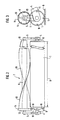
- the support roller 1 is arranged behind the rotor 2 of a lawn mower 3.
- the support roller 1 is connected to the frame of the lawn mower 3 via the connecting arm 4.
- the connecting arm 4 is adjustable in height relative to the frame of the lawnmower, so that the working height of the rotor 2 of the lawnmower 3 can be adjusted.
- a further holding arm 5 for mounting the stripper shaft 6 of the stripper 7 is arranged on the holding arm 4.
- the support roller 1 is freely rotatably supported in the holding arm 4 by means of the bearing pin 8.
- the support roller 1 rolls with its roller jacket on the floor surface 9.
- Four drive pins 11 are welded onto one end face 10 of the support roller 1. These drive pins 11 are arranged on a circular arc at a distance from one another.
- the scraper shaft 6 of the scraper 7 is mounted in the holding arms 5 so that it can rotate freely by means of the bearing pins 12.
- the wiper shaft 6 of the wiper 7 has two opposite stripper elements 13. These stripper elements 13 extend in the radial direction. Furthermore, the wiper elements 13 extend in the longitudinal direction of the support roller 1 over at least approximately their entire width B.
- the wiper elements 13 are arranged on the drive shaft 6 in a helical manner.
- the drive wheel 14 is arranged at one end of the wiper shaft 6.
- the drive wheel 14 is arranged with respect to the support roller on the side of the stripper shaft 6 on which the drive pins 11 are arranged on the support roller 1.
- the drive wheel 14 is provided on its circumferential outer surface with the rubberized outer layer 15. This rubberized outer layer 15 is elastic, so that the drive pins can press into the outer view 15 somewhat for a safe drive.
- the drive pins 11 and the drive wheel 14 are arranged relative to one another in such a way that the drive pins 11 rotate the drive wheel 14 and thus the stripper shaft 6 intermittently.
- the wiper 7 is driven intermittently by the corresponding arrangement of the wiper pins 11 at a distance from one another. As a result, he stands still for a while and is then rotated a little further.
- the wiper elements 13 of the wiper 7 are designed to be elastic and are made, for example, of rubber or plastic.
- the two opposite stripper elements 13 are rotated between 160 ° and 360 ° per meter working width, preferably by approximately 240 ° per meter working width.
- the stripper shaft 6 is rotated with the stripper elements 13 in such a way that the stripper shaft 6 is designed to be stationary in a self-locking manner so that it does not rotate solely due to the abutment on the roll shell of the backup roll.
- the scraper shaft 6 only rotates when it rotates a little further from the drive pins 11 becomes.
- the scraper shaft 6 is thus rotated only intermittently, that is to say intermittently, by driving the drive wheel 14 via the drive pins 11.
- the contact surface of the stripper elements 13 on the roll shell of the support roll 1 is not sufficient to rotate the stripper shaft 6. This is deliberately so intended, because the temporary standstill and only the incremental rotation of the drive shaft 6 results in an excellent wiping action and a very good cleaning of the support roller 1.
- the position of the scraper in relation to the support roller shown in FIGS. 1-3 is particularly suitable for lawn mowers.
- the scraper shaft is arranged on the back of the support roller as close as possible to the surface of the soil.
Applications Claiming Priority (2)
| Application Number | Priority Date | Filing Date | Title |
|---|---|---|---|
| DE4004276A DE4004276A1 (de) | 1990-02-13 | 1990-02-13 | Stuetzwalze |
| DE4004276 | 1990-02-13 |
Publications (2)
| Publication Number | Publication Date |
|---|---|
| EP0442290A1 true EP0442290A1 (fr) | 1991-08-21 |
| EP0442290B1 EP0442290B1 (fr) | 1993-08-11 |
Family
ID=6399973
Family Applications (1)
| Application Number | Title | Priority Date | Filing Date |
|---|---|---|---|
| EP91100729A Expired - Lifetime EP0442290B1 (fr) | 1990-02-13 | 1991-01-22 | Rouleau de soutien |
Country Status (2)
| Country | Link |
|---|---|
| EP (1) | EP0442290B1 (fr) |
| DE (3) | DE9007506U1 (fr) |
Cited By (10)
| Publication number | Priority date | Publication date | Assignee | Title |
|---|---|---|---|---|
| EP0680686A1 (fr) * | 1994-05-02 | 1995-11-08 | Deere & Company | Décrotteur pour rouleau plombeur qui contrôle la profondeur de semis |
| US6620723B1 (en) | 2000-06-27 | 2003-09-16 | Applied Materials, Inc. | Formation of boride barrier layers using chemisorption techniques |
| US6720027B2 (en) | 2002-04-08 | 2004-04-13 | Applied Materials, Inc. | Cyclical deposition of a variable content titanium silicon nitride layer |
| US6729824B2 (en) | 2001-12-14 | 2004-05-04 | Applied Materials, Inc. | Dual robot processing system |
| US6827978B2 (en) | 2002-02-11 | 2004-12-07 | Applied Materials, Inc. | Deposition of tungsten films |
| US6833161B2 (en) | 2002-02-26 | 2004-12-21 | Applied Materials, Inc. | Cyclical deposition of tungsten nitride for metal oxide gate electrode |
| US7905959B2 (en) | 2001-07-16 | 2011-03-15 | Applied Materials, Inc. | Lid assembly for a processing system to facilitate sequential deposition techniques |
| CN106416518A (zh) * | 2016-10-25 | 2017-02-22 | 连云港市兴安机械制造有限公司 | 一种地轮刮泥飞刀装置 |
| EP3162181A1 (fr) * | 2015-10-28 | 2017-05-03 | Amazonen-Werke H. Dreyer GmbH & Co. KG | Unité de traitement mobile destinée à l'entretien d'espaces verts |
| NL2022908B1 (nl) * | 2019-04-09 | 2020-10-20 | Vanmac Beheer B V | Grondoppervlakbewerkingsinrichting |
Families Citing this family (2)
| Publication number | Priority date | Publication date | Assignee | Title |
|---|---|---|---|---|
| US6911391B2 (en) | 2002-01-26 | 2005-06-28 | Applied Materials, Inc. | Integration of titanium and titanium nitride layers |
| US7279432B2 (en) | 2002-04-16 | 2007-10-09 | Applied Materials, Inc. | System and method for forming an integrated barrier layer |
Citations (5)
| Publication number | Priority date | Publication date | Assignee | Title |
|---|---|---|---|---|
| US2079979A (en) * | 1933-12-20 | 1937-05-11 | Edward H Worthington | Lawn mower |
| US2261893A (en) * | 1939-11-27 | 1941-11-04 | Wolfard Noah Ellsworth | Earth roller |
| DE8519861U1 (de) * | 1985-07-10 | 1985-09-05 | Rabewerk Heinrich Clausing, 4515 Bad Essen | Bodenwalze für die Bodenbearbeitung in der Landwirtschaft |
| EP0255751A1 (fr) * | 1986-08-06 | 1988-02-10 | C. van der Lely N.V. | Machine pour le travail du sol |
| EP0345899A1 (fr) * | 1988-06-10 | 1989-12-13 | C. van der Lely N.V. | Machine pour travailler le sol |
-
1990
- 1990-02-13 DE DE9007506U patent/DE9007506U1/de not_active Expired - Lifetime
- 1990-02-13 DE DE4004276A patent/DE4004276A1/de not_active Withdrawn
-
1991
- 1991-01-22 EP EP91100729A patent/EP0442290B1/fr not_active Expired - Lifetime
- 1991-01-22 DE DE9191100729T patent/DE59100262D1/de not_active Expired - Fee Related
Patent Citations (5)
| Publication number | Priority date | Publication date | Assignee | Title |
|---|---|---|---|---|
| US2079979A (en) * | 1933-12-20 | 1937-05-11 | Edward H Worthington | Lawn mower |
| US2261893A (en) * | 1939-11-27 | 1941-11-04 | Wolfard Noah Ellsworth | Earth roller |
| DE8519861U1 (de) * | 1985-07-10 | 1985-09-05 | Rabewerk Heinrich Clausing, 4515 Bad Essen | Bodenwalze für die Bodenbearbeitung in der Landwirtschaft |
| EP0255751A1 (fr) * | 1986-08-06 | 1988-02-10 | C. van der Lely N.V. | Machine pour le travail du sol |
| EP0345899A1 (fr) * | 1988-06-10 | 1989-12-13 | C. van der Lely N.V. | Machine pour travailler le sol |
Cited By (11)
| Publication number | Priority date | Publication date | Assignee | Title |
|---|---|---|---|---|
| EP0680686A1 (fr) * | 1994-05-02 | 1995-11-08 | Deere & Company | Décrotteur pour rouleau plombeur qui contrôle la profondeur de semis |
| US6620723B1 (en) | 2000-06-27 | 2003-09-16 | Applied Materials, Inc. | Formation of boride barrier layers using chemisorption techniques |
| US7905959B2 (en) | 2001-07-16 | 2011-03-15 | Applied Materials, Inc. | Lid assembly for a processing system to facilitate sequential deposition techniques |
| US10280509B2 (en) | 2001-07-16 | 2019-05-07 | Applied Materials, Inc. | Lid assembly for a processing system to facilitate sequential deposition techniques |
| US6729824B2 (en) | 2001-12-14 | 2004-05-04 | Applied Materials, Inc. | Dual robot processing system |
| US6827978B2 (en) | 2002-02-11 | 2004-12-07 | Applied Materials, Inc. | Deposition of tungsten films |
| US6833161B2 (en) | 2002-02-26 | 2004-12-21 | Applied Materials, Inc. | Cyclical deposition of tungsten nitride for metal oxide gate electrode |
| US6720027B2 (en) | 2002-04-08 | 2004-04-13 | Applied Materials, Inc. | Cyclical deposition of a variable content titanium silicon nitride layer |
| EP3162181A1 (fr) * | 2015-10-28 | 2017-05-03 | Amazonen-Werke H. Dreyer GmbH & Co. KG | Unité de traitement mobile destinée à l'entretien d'espaces verts |
| CN106416518A (zh) * | 2016-10-25 | 2017-02-22 | 连云港市兴安机械制造有限公司 | 一种地轮刮泥飞刀装置 |
| NL2022908B1 (nl) * | 2019-04-09 | 2020-10-20 | Vanmac Beheer B V | Grondoppervlakbewerkingsinrichting |
Also Published As
| Publication number | Publication date |
|---|---|
| DE9007506U1 (fr) | 1992-02-20 |
| DE59100262D1 (de) | 1993-09-16 |
| EP0442290B1 (fr) | 1993-08-11 |
| DE4004276A1 (de) | 1991-08-14 |
Similar Documents
| Publication | Publication Date | Title |
|---|---|---|
| EP0552709B1 (fr) | Tondeuse à gazon | |
| EP0442290B1 (fr) | Rouleau de soutien | |
| DE3711346A1 (de) | Drehbuerstenfeger mit mechanismus fuer die buerstenhoeheneinstellung | |
| DE2461748A1 (de) | Maehvorrichtung | |
| EP0808558B1 (fr) | Tondeuse cylindrique à râcleur pour le rouleau d'appui | |
| DE7147375U (de) | Kreiselegge | |
| DE69921252T2 (de) | Kehrmaschine mit beweglicher Rückführklappe | |
| EP0486473B1 (fr) | Machine agricole de préparation du sol | |
| DE2827786A1 (de) | Maehwerk mit breitstreueinrichtung | |
| DE3133324C2 (fr) | ||
| CH648986A5 (de) | Bodenbearbeitungsmaschine. | |
| DE202022101368U1 (de) | Fahrzeugrad-Reinigungsvorrichtung | |
| DE3939659A1 (de) | Erntemaschine | |
| DE1582346A1 (de) | Heuerntemaschine | |
| DE2150555A1 (de) | Heuwerbungsmaschine | |
| DE19515483A1 (de) | Wiesenbehandlungsgerät zum Anbau an einen Schlepper | |
| DE2607666A1 (de) | Kreiselmaehwerk | |
| DE8519861U1 (de) | Bodenwalze für die Bodenbearbeitung in der Landwirtschaft | |
| DE2924732A1 (de) | Bodenbearbeitungsmaschine | |
| DE2055841B2 (de) | Kehrmaschine, insbesondere mit Handantrieb | |
| DE2252246A1 (de) | Kreiselmaehwerk mit schlegelwalze | |
| EP0208010B1 (fr) | Rouleau pour le travail du sol en agriculture | |
| DE3338284A1 (de) | Bodenbearbeitungsmaschine | |
| DE1900165A1 (de) | Maehmaschine | |
| DE3422426A1 (de) | Landmaschine zum verlagern von auf dem boden liegendem erntegut |
Legal Events
| Date | Code | Title | Description |
|---|---|---|---|
| PUAI | Public reference made under article 153(3) epc to a published international application that has entered the european phase |
Free format text: ORIGINAL CODE: 0009012 |
|
| AK | Designated contracting states |
Kind code of ref document: A1 Designated state(s): DE DK FR GB NL |
|
| 17P | Request for examination filed |
Effective date: 19910823 |
|
| 17Q | First examination report despatched |
Effective date: 19920722 |
|
| GRAA | (expected) grant |
Free format text: ORIGINAL CODE: 0009210 |
|
| AK | Designated contracting states |
Kind code of ref document: B1 Designated state(s): DE DK FR GB NL |
|
| REF | Corresponds to: |
Ref document number: 59100262 Country of ref document: DE Date of ref document: 19930916 |
|
| GBT | Gb: translation of ep patent filed (gb section 77(6)(a)/1977) |
Effective date: 19930819 |
|
| ET | Fr: translation filed | ||
| PG25 | Lapsed in a contracting state [announced via postgrant information from national office to epo] |
Ref country code: DK Effective date: 19940122 |
|
| PLBE | No opposition filed within time limit |
Free format text: ORIGINAL CODE: 0009261 |
|
| STAA | Information on the status of an ep patent application or granted ep patent |
Free format text: STATUS: NO OPPOSITION FILED WITHIN TIME LIMIT |
|
| PG25 | Lapsed in a contracting state [announced via postgrant information from national office to epo] |
Ref country code: NL Effective date: 19940801 |
|
| 26N | No opposition filed | ||
| NLV4 | Nl: lapsed or anulled due to non-payment of the annual fee | ||
| PG25 | Lapsed in a contracting state [announced via postgrant information from national office to epo] |
Ref country code: GB Effective date: 19950122 |
|
| GBPC | Gb: european patent ceased through non-payment of renewal fee |
Effective date: 19950122 |
|
| PGFP | Annual fee paid to national office [announced via postgrant information from national office to epo] |
Ref country code: FR Payment date: 19951227 Year of fee payment: 6 |
|
| PGFP | Annual fee paid to national office [announced via postgrant information from national office to epo] |
Ref country code: DE Payment date: 19960117 Year of fee payment: 6 |
|
| PG25 | Lapsed in a contracting state [announced via postgrant information from national office to epo] |
Ref country code: FR Effective date: 19970930 |
|
| PG25 | Lapsed in a contracting state [announced via postgrant information from national office to epo] |
Ref country code: DE Effective date: 19971001 |
|
| REG | Reference to a national code |
Ref country code: FR Ref legal event code: ST |