EP0442058B1 - Pulvérisateur de liquides - Google Patents
Pulvérisateur de liquides Download PDFInfo
- Publication number
- EP0442058B1 EP0442058B1 EP90122820A EP90122820A EP0442058B1 EP 0442058 B1 EP0442058 B1 EP 0442058B1 EP 90122820 A EP90122820 A EP 90122820A EP 90122820 A EP90122820 A EP 90122820A EP 0442058 B1 EP0442058 B1 EP 0442058B1
- Authority
- EP
- European Patent Office
- Prior art keywords
- spray device
- liquid spray
- liquid
- chamber
- head piece
- Prior art date
- Legal status (The legal status is an assumption and is not a legal conclusion. Google has not performed a legal analysis and makes no representation as to the accuracy of the status listed.)
- Expired - Lifetime
Links
Images


Classifications
-
- B—PERFORMING OPERATIONS; TRANSPORTING
- B05—SPRAYING OR ATOMISING IN GENERAL; APPLYING FLUENT MATERIALS TO SURFACES, IN GENERAL
- B05B—SPRAYING APPARATUS; ATOMISING APPARATUS; NOZZLES
- B05B7/00—Spraying apparatus for discharge of liquids or other fluent materials from two or more sources, e.g. of liquid and air, of powder and gas
- B05B7/24—Spraying apparatus for discharge of liquids or other fluent materials from two or more sources, e.g. of liquid and air, of powder and gas with means, e.g. a container, for supplying liquid or other fluent material to a discharge device
- B05B7/2402—Apparatus to be carried on or by a person, e.g. by hand; Apparatus comprising containers fixed to the discharge device
- B05B7/2405—Apparatus to be carried on or by a person, e.g. by hand; Apparatus comprising containers fixed to the discharge device using an atomising fluid as carrying fluid for feeding, e.g. by suction or pressure, a carried liquid from the container to the nozzle
- B05B7/2424—Apparatus to be carried on or by a person, e.g. by hand; Apparatus comprising containers fixed to the discharge device using an atomising fluid as carrying fluid for feeding, e.g. by suction or pressure, a carried liquid from the container to the nozzle the carried liquid and the main stream of atomising fluid being brought together downstream of the container before discharge
- B05B7/2427—Apparatus to be carried on or by a person, e.g. by hand; Apparatus comprising containers fixed to the discharge device using an atomising fluid as carrying fluid for feeding, e.g. by suction or pressure, a carried liquid from the container to the nozzle the carried liquid and the main stream of atomising fluid being brought together downstream of the container before discharge and a secondary stream of atomising fluid being brought together in the container or putting the carried liquid under pressure in the container
-
- B—PERFORMING OPERATIONS; TRANSPORTING
- B05—SPRAYING OR ATOMISING IN GENERAL; APPLYING FLUENT MATERIALS TO SURFACES, IN GENERAL
- B05B—SPRAYING APPARATUS; ATOMISING APPARATUS; NOZZLES
- B05B11/00—Single-unit hand-held apparatus in which flow of contents is produced by the muscular force of the operator at the moment of use
- B05B11/01—Single-unit hand-held apparatus in which flow of contents is produced by the muscular force of the operator at the moment of use characterised by the means producing the flow
- B05B11/06—Gas or vapour producing the flow, e.g. from a compressible bulb or air pump
Definitions
- the invention relates to a liquid spray device according to the preamble of claim 1.
- a liquid spray device of this type is known from GB-A-299 280.
- the air pump comparable to a bicycle pump is located on a head piece opposite the end of the housing of the liquid spray device.
- the head piece, a nozzle, can be unscrewed.
- the liquid can be assigned to the housing of the liquid spraying device in a refillable manner via a lateral nipple or it is held ready by a screw vessel which is laterally assigned to a yolk sac. To this extent, there is a screw vessel refitting.
- the exposed position of the screw vessel is not just an obstacle to handling; it also leaves the screw vessel largely unprotected.
- the excess air pressure is passed through a bypass-type outer line into the housing to form an excess pressure air cushion which expresses the liquid via a liquid level and atomizes the liquid steel in the screw-off nozzle with a branch.
- This liquid spraying device is otherwise difficult to manufacture and laborious to operate, especially since the outlet valve is designed as a shut-off valve sitting on the outer line.
- a liquid spray device of this type is also known from US-A-4 167 941.
- the air pump is operated there via a handle on the head piece.
- the overpressure cushion that builds up is available as a storage force.
- the liquid is squeezed out by actuating a dispensing valve on the head piece side.
- the storage device consists of a chamber with a piston disk guided freely therein, which rests on a compression spring which correspondingly tightens with increasing filling of the respective chamber.
- the overpressure cushion is built up via several small pistons using a rotary movement of the said handle.
- the pistons which are arranged radially and in opposite directions transversely to the longitudinal center axis of the liquid spraying device, engage with their piston shaft via a control pin in a zigzag-shaped link slot which, taking into account the rotatability of the dispenser head, follows an undulating circular path. That requires a lot of "shooting".
- the object of the present invention is to manufacture a generic liquid spray device simple, advantageous use so that - even using the interchangeable cartridge principle - a strong, so-called “dry” spray jet is achieved without the need for springs.
- a generic liquid spray device which is characterized by a simple structure and perfect function.
- a special spring body cf. US-A-4 167 941
- a stable spray jet profile is achieved, so that the most varied of media can be applied, and above all the more environmentally friendly cartridge system can be used with advantage.
- the space is a cartridge receiving space which has an annular gap on the jacket wall side as a compressed air connection right into the head piece.
- the operating medium can therefore be stored in columns and rooms that are already present, above all taking into account the space accommodating the cartridge.
- there is the head area i.e. the space available in the head piece.
- the unit that creates the corresponding overpressure air cushion sits in the end conveniently remote from the head piece.
- the latter therefore remains easily removable for the insertion of the next, full cartridge or the removal of the empty cartridge.
- a plug connection nipple arranged on the head piece projects into the cartridge receiving space, through which the inside of the cartridge is connected to the air pressure. This results in a balanced distribution of the overpressure air cushion, one part causing the liquid to be raised or brought in and the other part ensuring surprisingly good atomization.
- the plug-in connection nipple has a liquid lock.
- liquid itself is thus prevented from unintentionally escaping into the surrounding overpressure cushion, whereas the air itself reaches the interior of the cartridge via the plug connection nipple.
- a liquid barrier is achieved with simple means in that the liquid barrier is formed by an annular membrane of the plug-in connection nipple, which rests with its lip edge sealingly on the jacket wall of a riser pipe conducting the liquid into the head piece.
- the corresponding lip rim in combination with enough flexible material of such a plug nipple appears extremely sensitive; separate formations of such a membrane are therefore not required.
- the air pump handle is designed as a rotating sleeve which guides itself on the housing of the liquid spray device and is connected to an air pump piston which runs in a cylinder chamber located in the housing.
- the outer shape of the housing is advantageously used here as a guide means for the rotating sleeve and the inner area for the assignment and design of the cylinder chamber.
- an advantageous embodiment is achieved by controlling the linkage of the piston / air pump handle functional unit. It is also proposed that the cylinder chamber of a retraction of the housing is formed and the means of the gate control are accommodated in the remaining storage room.
- the procedure is further specifically such that it is formed by rising grooves on the inside of the air pump handle, into which grooves a stationary, radial guide pin of the housing engages as a so-called sliding block.
- Such cones can also be taken into account in the injection molding process.
- the guide pins are fitted with rollers in order to achieve a particularly smooth sliding guide.
- the grooves are assigned essentially axial insertion shafts, which in the assembled state are blocked by a steeply sloping back comb of the one link part.
- an advantageous embodiment is achieved by a flatter course of the rising grooves in the final phase of the pumping movement, which also form support pockets for the guide pins in both ends.
- the support pockets define the end positions, so that a pitch angle for the grooves is applicable, which is far outside the self-locking.
- the finite limitation of the grooves lies on a working stroke of approx. 135 °. This results in a convenient mode of operation, since the operating hand is not overused, i.e. the ergonomic one Conditions is taken into account.
- a favorable measure also lies in the fact that the cylinder chamber has a transverse wall carrying the pump valve on the cartridge side, which divides the retraction with respect to the cartridge receiving space of the housing to form a pressure prechamber.
- This centrally located pressure pre-chamber leads to an even distribution of the overpressure air cushion in a zone immediately downstream of the pressure source, ie pressure pump.
- the air pump piston carries a piston sleeve with an end annular space.
- Such an annular space expediently lies in the edge area of the sleeve, thus leading on the one hand to the highly elastic or flexible sleeve lip typical of the sleeve and on the other hand to a stable transition to the remaining central area of the sleeve designed as a pot or plate.
- the piston sleeve assumes a further function insofar as it also forms the valve tab of an intake valve of the cylinder chamber and a cap screwed to the air pump handle is clipped onto the pot-shaped end drawn in on the housing side. In this way, the piston continues as the inner leg of a rotationally symmetrical U-profile of the handle, which surrounds the lower end of the housing.
- the plug connection nipple of a perforated holding plate is formed centrally, which is framed between the upper front end of the housing and the screw-connected head piece and continues into a counter-nipple plug-connected to the head piece.
- the counter nipple is used in the head area to form a rotationally symmetrical Y-channel, the Y-web of which leads to the dispensing valve and the outer Y-leg connects via a transverse channel to a headpiece chamber which is located above the cartridge - Recording room extends.
- the centering effect of the plug connection nipple leaves a uniform annular space between the jacket wall of the cartridge and the inner wall of the housing.
- the outlet valve can be actuated by a spray head pushbutton which is spring-loaded in the direction of the closed basic position.
- the pressure in the cartridge receiving space is identical to the pressure in the end annular space of the piston when the piston is in its retracted end position, it is no longer possible to inflate the cartridge receiving space etc. As a result, the safety of use of the liquid spray device described is also optimal.
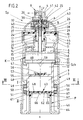
- the dispenser Sp containing the liquid spray device according to the invention is designed as an elongated, essentially cylindrical free-standing device, consisting of a housing 1, a removable head piece 2 and a handle 3. The latter is used to actuate an air pump P.
- the air pump handle 3 sits on the end of the housing 1 opposite the head piece 2.
- the air pump P creates an overpressure cushion in the interior of the dispenser.
- This actuates a discharge valve 4 contained in the dispenser by actuating an outlet valve 4 on the head piece side, by this overpressure air cushion loading both the mirror 6 of the liquid 5 and atomizing it by mixing with the liquid jet.
- the liquid jet emerges from a so-called nozzle 7 of a corresponding spray device 8.
- the added air component leads to a dimensionally stable, so-called "dry" spray jet.
- the overpressure cushion building up in the dispenser Sp is generated in a cylinder chamber 9 of the air pump P. From there, the compressed air arrives in a pressure prechamber 10. From here the distribution takes place in the section of the housing 1 which holds the liquid 5 containing cartridge K is used. It is interchangeably assigned to the donor Sp. It has a diameter such that the cartridge-receiving space 11 leaves an evading annular gap 12 on the jacket wall side, so that compressed air connection is present into the head piece 2, that is to say toward the spray device 8.
- the cartridge K is designed in the form of a bottle and consequently merges into a neck 14 at its end facing away from the edge-reinforced base 13.
- the neck 14 arises from the axially approximately drawn-in cover 15 of the cartridge K and has a cylindrical mouth 16.
- the free space of the housing 1 around the neck 14 and also axially above it ends with a holding plate 17. It is perforated. These are openings 18, one of which can be seen in FIG. 1. Via the latter (18), the compressed air gains connection to the dome-shaped interior of the head piece 2, more precisely that Head chamber 2 '. From here, the branching or division takes place in the sense explained above.
- connection on the cartridge side is formed by a plug-in connection nipple 19 starting from the holding plate 17 and indirectly connected to the head piece 2. It overlaps into the cylindrical mouth 16 of the neck 14. So there is a kind of pipe coupling.
- the lower outer edge of the plug connection nipple 19 has a sealing bead 20. Via the plug connection nipple 19, the interior 21 of the cartridge K is connected to the excess air pressure.
- the liquid 5 is prevented from escaping through the mouth 16 of the neck 14 into the cartridge receiving space 11, for example in cases in which the dispenser Sp is used in an upside-down position for spraying.
- the plug-in connection nipple 19 has a liquid barrier that only allows the passage of air.
- it is a relatively thin-walled ring membrane 22. The latter, with its lip edge, which may be pointed, seals and only yields to the air pressure on the jacket wall of a riser pipe 23 which conducts the liquid 5 into the head piece 2.
- the riser pipe 23 starts from the removable head piece 2. It extends in the longitudinal central axis x-x of the dispenser Sp and extends to the bottom 13 of the cartridge K, but leaving a small distance from it (13), so that the liquid can enter the lower end of the riser pipe 23 unhindered.
- the other, upper end of the riser pipe 23 is on a central, downward directed, into the mouth 14 protruding nozzle 24, which is coaxial to a spring chamber 25 arranged above, the wall forming an upwardly open pot continues over a pot edge into a bush part 26 open in the opposite direction, which, concentrically and at a distance from the spring chamber 25, extends one of the Top of the holding plate 17 receives outgoing nipples.
- the latter leaves between its jacket wall and the inner wall of the bushing part 26 an annular channel 28 which is connected to the overpressure air cushion via one or more openings 29.
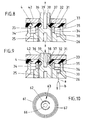
- the edge serving as a cross connection between the wall of the spring chamber 25 and the bush part 26 has openings 30. This also clears the way to the closing outlet valve 4 (cf. FIG. 9).
- the outlet valve 4 consisting of a horizontally embedded annular disk 31 made of elastic material rests on annular walls 32 and 33 arranged concentrically to the longitudinal central axis xx.
- the inner annular wall 33 forming the spring chamber 25 has transverse channels 34. The latter provide the connection between the spring chamber and a circumferential cavity 35 below the washer 31 ago.
- a central shaft 36 This has an annular groove 37 at the level of the annular disk 31. At the bottom of the annular groove there is at least one branch channel 38. The latter connects the liquid and air-permeable annular space section of the spring chamber 25 to a central outlet channel 39 which is connected directly to the transversely outgoing nozzle 7.
- the lower end of the aforementioned shaft 36 extends into the spring chamber 25 and supports the upper end turn of the compression spring 40 loading the outlet valve in the direction of the closed position.
- the other end turn rests on an annular shoulder between the connecting piece 24 and the wall circumscribing the annular chamber 25.
- the outlet valve 4 is actuated via a free-standing spray head pushbutton 41 of the head piece 2 which is spring-loaded in the direction of the closed basic position.
- the upper-side boundary system for the ring disk 31 forms a hat-shaped plug-in part 42, which is held in an annular groove of a cylindrical recess 43 of the head piece 2 and guides the shaft 36 above the ring disk 31.
- the holding plate 17 which brings the plug connection via plug connection nipple 19 to the cartridge K is framed peripherally between the upper end edge 1 'of the housing 1 and the head piece 2 connected to it by screws.
- a centering projection 44 which, despite the elasticity of the material used, since this also has to form the membrane 22, gives the edge section and the entire component a high degree of internal stability.
- a bell-shaped edge 45 with a corresponding internal thread is formed on the rotationally symmetrical head piece 2, which engages in the corresponding external thread of the housing 1.
- the described channel situation in the dispenser head leads to the counter nipple 27 in the head piece 2 being used to form a rotationally symmetrical Y channel, the Y web a of which points to the outlet valve 4, the outer Y leg b via the opening 30 to the head piece.
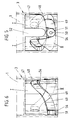
- the procedure here is further such that the air pump handle 3 is designed as a rotating sleeve which guides the housing 1 of the liquid spraying device and is connected to an air pump piston 46.
- the lower section of the housing 1 merges into a recess 47 which is clearly recognizable from the drawing.
- the offset space 48 remaining through the indentation 47 accommodates the means of a link control that displaces the piston 46.
- the offset space 48 means the space which extends between the cylindrical jacket wall of the recess 47 and the likewise cylindrical inner wall of the handle 3 guided on the housing 1.
- the slim shape of the dispenser is retained.
- the link control is formed by two helically rising, raidal inwardly directed open grooves 49. These are located on the inside of the air pump handle 3. They are assigned in a non-overlapping manner and each work with a fixed, radially outwardly directed guide pin 50 of the housing 1 respectively his confiscation 47 together.
- each of the two guide pins 50 arranged in a diametrically opposed position each carry a roller 51.
- the latter can be attached loosely be, since the axially extending inner wall of the handle 3 has a locking effect.
- the same essentially axially aligned insertion shafts 52 are assigned, which in the assembled state, as can be seen from the development in FIG. 7, can be closed with a steeply falling back comb 53.
- the shoulder Sch adjoining the pressure pre-chamber 10 has support ribs 59 formed on the top side, so that between the surface-stable bottom 13 of the cartridge K and the offset housing inner profile passages 60 remain. As a result, the upper edges of the support ribs 59 form the actual annular cartridge shelf in the housing 1.
- the piston 46 of the air pump P carries a piston sleeve 61. It is a hat-shaped body made of elastic material such as rubber or the like. In this respect, it is also suitable for performing a double function, which consists in the piston sleeve 61 simultaneously forming the valve flap 62 of an inlet valve 63 of the pump P seated on the piston 46.
- the piston sleeve 61 is clipped onto the end of a cap 64 which is screwed to the air pump handle 3 and is also cup-shaped and drawn in on the housing side.
- the fastening-side end of the piston 46 forms a corresponding mushroom head, which is gripped behind by an edge bead 61 'on the inner edge of the cup-shaped sleeve.
- valve flap 62 The zone forming the actual valve flap 62 and also the further horizontal surroundings lie flat on the flat underside of the pot base or, better said, the ceiling 65 of the pot-like retraction. In the center of this blanket, which is denoted by 65, there is also a valve opening 66. In the pushed-in end position of the piston 46, the flat top of the sleeve lies flush with the underside of the transverse wall 55, leaving the light gap shown in FIG. 1.
- a further embodiment of the piston sleeve consists in the creation of an end annular space 67.
- the latter has a V-shaped cross section, but can also be a trapezoidal cross section.
- the V opening points in the direction of the flat transverse wall 55.
- the purpose of the peripheral notch is on the one hand to create the cuff-like piston lip, which is undercut, and on the other hand also the creation of a pump limiter. If the pressure in the cartridge receiving space is identical to the pressure in the annular space 67 of the piston 46, further inflation of the cartridge receiving space 11 is no longer possible. In the end of pressure position, the pump piston closes the overflow opening to the cartridge receiving chamber 11 and in this position leaves a compression space.
- the handling and function of the described dispenser is as follows: After pulling off a protective cap 68 covering the head piece 2, the spray head pushbutton 41 is free to exert a compressive force in the direction of the arrow z.
- the housing 1 In order to create or renew or supplement the overpressure cushion required for dispensing the liquid 5, the housing 1 is gripped with one hand; with the other hand, the operator performs reciprocating rotary movements on the handle 3.
- the gate control leads to a superimposed rotary and axial stroke movement of the piston 46.
- the overpressure thus generated is distributed starting from the pressure pre-chamber 10 so that the liquid 5 in the cartridge K is under pressure and compressed air is also present in front of the outlet valve 4. If this is brought into the open position according to FIG. 9, then both components, air plus liquid, enter the outlet channel 39 via the branch channel 38, passing the nozzle 7 with further mixing and forming the desired dimensionally stable jet.
- the compressed air passes through the annular membrane 22, which acts like a lock, but which in turn does not allow any liquid to get into the remaining head chamber 2 'when the dispenser is in a tilted position.
- the overpressure rises the elastic counter-nipple 27 from the corresponding inner wall of the socket part 26.
- the spray jet can be interrupted as soon as the spray device 8 or the spray head pushbutton 41 is released, which, due to the restoring force of the spring 40, returns to its closed starting position.
- the scenery parts circumscribing the groove can be created as individual pieces or at least one of the two parts of the handle 3 can be molded in the same way. In the exemplary embodiment, this is the upper part I.
- the lower part II is therefore fastened in the classic manner. All individual parts can be injection molded from plastic; only the compression spring 40 is made of stainless steel.
- the container section of the cartridge K can be designed as a sack, but the cover 15, also having the neck shape described, is designed as a hard part which is connected to the edge of the sack.
- the bag bottom is also stiffened so that the passages 60 do not become clogged.
Claims (18)
- Dispositif de pulvérisation de liquide avec une pompe à air (B), à actionner manuellement par l'intermédiaire d'une poignée (3), dont le coussin d'air en surpression expulse le liquide (5), en cas d'actionnement d'une valve d'évacuation (4) situé côté pièce de tête, un espace susceptible d'être exposé à la surpression de l'air étant situé entre la pièce de tête (2) amovible et la poignée de pompe à air (3) disposée à l'extrémité opposée, caractérisé en ce que l'espace est un espace de logement de cartouche (11), présentant, côté paroi-enveloppe, un interstice annulaire (12) servant de raccordement d'air comprimé et s'étendant jusqu'à la pièce de tête (2)
- Dispositif de pulvérisation de liquide selon la revendication 1, caractérisé en ce que, dans l'espace de logement de cartouche (11), pénètre un manchon de raccordement à enfichage (19), disposé sur la pièce de tête (2) et au moyen duquel le volume intérieur (21) de la cartouche (K) est reliée à la surpression d'air.
- Dispositif de pulvérisation de liquide selon la revendication 2, caractérisé en ce que le manchon de raccordement à enfichage (9) présente un verrou à liquide.
- Dispositif de pulvérisation de liquide selon la revendication 3, caractérisé en ce que le verrou à liquide est constitué par une membrane annulaire (22) du manchon de raccordement à enfichage (19), qui repose par sa paroi de lèvre, avec étanchéité, sur la paroi enveloppe d'un tube d'exhaure (23) servant à diriger le liquide (5) dans la pièce de tête (2).
- Dispositif de pulvérisation de liquide selon l'une ou plusieurs des revendications précédentes, caractérisé en ce que la poignée de pompe à air (3) est réalisée sous forme d'une douille tournante, guidée sur le boîtier (1) du dispositif de pulvérisation de liquide et reliée à un piston de pompe à air (46) se déplaçant dans une chambre cylindrique (9) se trouvant dans le boîtier (1).
- Dispositif pulvérisation de liquide selon la revendication 5, caractérisé par une commande à coulisse (49/50) de l'ensemble poignée de pompe à air/piston (9/3).
- Dispositif de pulvérisation de liquide selon l'une des revendications 5 ou 6, caractérisé en ce que la chambre cylindrique (9) est constituée par un rétrécissement (47) du boîtier (1) et les moyens de la commande à coulisse (49/50) étant logés dans l'espace en retrait (48) subsistant.
- Dispositif de pulvérisation de liquide selon la revendication 7, caractérisé en ce que l'épaulement (Sch) constitué par le rétrécissement (47) sert de fond de pose de cartouche, laissant subsister des passages (60).
- Dispositif de pulvérisation de liquide selon l'une des revendications précédentes 6 à 8, caractérisé en ce que la commande à coulisse est constituée par des rainures (49) montante, ménagées en face intérieure de la poignée de pompe à air (3), rainures (49) dans chacune desquelles s'engage un tourillon de guidage radial (50), localement fixe, du boîtier (1).
- Dispositif de pulvérisation de liquide selon la revendication 9, caractérisé en ce que les tourillons de guidage (50) sont équipés de galets et des puits d'introductions (52), sensiblement axiaux, sont associés aux rainures (49), lesdits puits étant bloqués à l'état monté au moyen d'une dent ou peigne de rappel (53) venant y tomber de façon raide, et appartenant à une partie de coulisse.
- Dispositif de pulvérisation de liquide selon l'une des revendications 9 ou 10 précédentes, caractérisé par une allure plus plate des rainures (49) montantes, dans leur phase finale d'actionnement de la pompe, ces rainures (49) constituant aux deux extrémités des cavités d'appui (54) pour les tourillons de guidage (50).
- Dispositif de pulvérisation de liquide selon l'une ou plusieurs des revendications 7 à 11 précédentes, caractérisé en ce que la chambre cylindrique (11) comporte une paroi transversale (55) portant, côté cartouche, la soupape de pompe (56) et subdivisant le rétrécissement (47) par rapport à l'espace de logement de cartouche (11) du boîtier (1), en constituant une préchambre de pression (10).
- Dispositif de pulvérisation de liquide selon l'une ou plusieurs des revendications précédentes, caractérisé en ce que le piston de pompe à air (46) porte une manchette de piston (61) à espace annulaire frontal (67).
- Dispositif de pulvérisation de liquide selon la revendication 13, caractérisé en ce que la manchette de piston (61) constitue en même temps la languette de soupape (62) d'une valve d'admission (63) de la chambre cylindrique (9) et encliquetée sur l'extrémité en forme de pot, rétrécie côté boîtier, d'un capuchon (64) lié par vissage à la poignée de pompe à air (3).
- Dispositif de pulvérisation de liquide selon une ou plusieurs des revendications 2 à 14 précédentes, caractérisé en ce que le manchon de raccordement à enfichage (19) est formé au centre d'une plaque de maintien (17) perforée, saisie en bordure entre l'extrémité frontale supérieur (1') du boîtier (1), et la pièce de tête (2) lui étant reliée par vissage et se prolongeant en un manchon conjugué (27) relié par enfichage à la pièce d'enfichage (2).
- Dispositif de pulvérisation de liquide selon la revendication 15, caractérisé en ce que le manchon conjugué (27) ménagé dans la pièce de tête (2) est utilisé conjointement pour constituer un canal en Y présentant une symétrie de rotation, dont la jambe du Y (a) mène à la valve d'évacuation (4) et la branche extérieure de Y (b) se raccorde, par un passage (30), à une chambre de pièce de tête (2') qui s'étend au dessus de l'espace de logement de cartouche (11).
- Dispositif de pulvérisation de liquide selon l'une ou plusieurs des revendications précédentes, caractérisé en ce que la valve d'évacuation (4) est actionnable par un bouton poussoir de tête de pulvérisation (41), sollicité par un ressort en direction de la position de base de fermeture.
- Dispositif de pulvérisation de liquide selon l'une ou plusieurs des revendications 13 à 17 précédentes, caractérisé par un espace annulaire frontal (67) de la manchette de piston (61), servant de limiteur de pompage.
Applications Claiming Priority (2)
| Application Number | Priority Date | Filing Date | Title |
|---|---|---|---|
| DE4004653 | 1990-02-15 | ||
| DE4004653A DE4004653A1 (de) | 1990-02-15 | 1990-02-15 | Fluessigkeitsspruehvorrichtung |
Publications (3)
| Publication Number | Publication Date |
|---|---|
| EP0442058A2 EP0442058A2 (fr) | 1991-08-21 |
| EP0442058A3 EP0442058A3 (en) | 1992-02-19 |
| EP0442058B1 true EP0442058B1 (fr) | 1995-01-11 |
Family
ID=6400188
Family Applications (1)
| Application Number | Title | Priority Date | Filing Date |
|---|---|---|---|
| EP90122820A Expired - Lifetime EP0442058B1 (fr) | 1990-02-15 | 1990-11-29 | Pulvérisateur de liquides |
Country Status (7)
| Country | Link |
|---|---|
| US (1) | US5405060A (fr) |
| EP (1) | EP0442058B1 (fr) |
| AT (1) | ATE116872T1 (fr) |
| DE (2) | DE4004653A1 (fr) |
| DK (1) | DK0442058T3 (fr) |
| ES (1) | ES2066942T3 (fr) |
| GR (1) | GR3015745T3 (fr) |
Families Citing this family (16)
| Publication number | Priority date | Publication date | Assignee | Title |
|---|---|---|---|---|
| DE4108428A1 (de) * | 1991-03-15 | 1992-09-17 | Wiegner Georg Dipl Kaufm | Vorrichtung zur dosierten abgabe von unter druck stehenden inhaltstoffen |
| DE4136826A1 (de) * | 1991-11-08 | 1993-05-13 | Pfeiffer Erich Gmbh & Co Kg | Austragvorrichtung fuer medien |
| DE9217250U1 (fr) * | 1992-12-17 | 1993-02-11 | Wella Ag, 6100 Darmstadt, De | |
| US6991136B2 (en) * | 2001-11-26 | 2006-01-31 | De La Guardia Mario Felix | Pressurizing device for attachment to fluid containers |
| US20040164083A1 (en) * | 2003-02-26 | 2004-08-26 | Lin Arlo H. T. | Bag for use in gas can |
| KR100782330B1 (ko) * | 2006-07-14 | 2007-12-06 | 주식회사 예찬 | 용기 출몰식 펌프디스펜서 |
| US8177101B1 (en) * | 2007-02-06 | 2012-05-15 | William Sydney Blake | One turn actuated duration spray pump mechanism |
| GB2493352A (en) * | 2011-08-01 | 2013-02-06 | Owen Brown | A sprayer comprising a detachable product module and an air pressurisation apparatus. |
| NL1039048C2 (nl) * | 2011-09-17 | 2013-03-25 | Henri Peteri Beheer Bv | Zeeppomp. |
| US9415401B2 (en) | 2012-04-04 | 2016-08-16 | Alternative Packaging Solutions Llc | One turn actuated duration spray pump mechanism |
| US8908896B2 (en) * | 2012-06-29 | 2014-12-09 | Intel Corporation | Earpiece for an electronic device |
| US20140183222A1 (en) * | 2012-10-19 | 2014-07-03 | Rust-Oleum Corporation | Propellantless Aerosol System |
| WO2015178917A1 (fr) * | 2014-05-22 | 2015-11-26 | Colgate-Palmolive Company | Cartouche de recharge, système comprenant la cartouche de recharge et distributeur à pompe |
| DE202016006615U1 (de) * | 2016-10-26 | 2018-01-30 | WIK - ELEKTROGERÄTE Entwicklungs- und Service-GmbH & Co. KG | Haarformgerät zur Beaufschlagung eines Pflegestoffes mittels Druckluft |
| CN116600902A (zh) | 2020-12-15 | 2023-08-15 | 联合利华知识产权控股有限公司 | 喷雾分配器 |
| US20240091800A1 (en) | 2020-12-15 | 2024-03-21 | Conopco, Inc., D/B/A Unilever | Spray dispenser |
Family Cites Families (30)
| Publication number | Priority date | Publication date | Assignee | Title |
|---|---|---|---|---|
| US337943A (en) * | 1886-03-16 | Clabence a | ||
| GB189507723A (en) * | 1895-04-17 | 1895-08-31 | Henry Bartz | An Improved Mustard Pot. |
| US1080835A (en) * | 1912-09-20 | 1913-12-09 | George J Kelley | Atomizer. |
| GB179740A (en) * | 1921-03-12 | 1922-05-18 | Charles Alfred Outwin Saxelby | Improvements relating to spraying apparatus |
| GB299280A (en) * | 1928-06-01 | 1928-10-25 | Walter Roy Weeks | Improvements in apparatus for spraying paint, varnish, lacquer or the like |
| US1967743A (en) * | 1933-05-05 | 1934-07-24 | Russell H Chaille | Dispenser |
| US2060512A (en) * | 1935-12-16 | 1936-11-10 | Herbert L Magill | Liquid dispensing device |
| US2608320A (en) * | 1947-03-31 | 1952-08-26 | Jr Joseph R Harrison | Pump type dispenser with cartridge having flexible and rigid portions |
| US2598869A (en) * | 1949-05-03 | 1952-06-03 | White James Adelbert | Pressure operated pipette filler |
| US2710711A (en) * | 1952-01-25 | 1955-06-14 | Hutton Dorothy Dear | Medicinal applicator |
| US3207387A (en) * | 1963-10-16 | 1965-09-21 | Brickman Robert | Portable sprayer |
| US3198405A (en) * | 1964-04-29 | 1965-08-03 | William C Pfeil | Dispenser |
| GB1379182A (en) * | 1971-06-10 | 1975-01-02 | Yoshino Kogyosho Co Ltd | Spraying device |
| US3955720A (en) * | 1972-11-15 | 1976-05-11 | Malone David C | Low pressure dispensing apparatus with air pump |
| FR2320788A2 (fr) * | 1975-08-14 | 1977-03-11 | Pulverisation Step Ste Tech | Perfectionnements apportes aux vaporisateurs |
| FR2342915A1 (fr) * | 1976-03-02 | 1977-09-30 | Henry Rene | Aerosol rechargeable |
| US3995779A (en) * | 1976-03-17 | 1976-12-07 | Lawrence Peska Associates, Inc. | Aerosol container |
| US4167941A (en) * | 1976-10-05 | 1979-09-18 | James D. Pauls, Ltd. (Limited Partnership) | Mechanically operated dispensing device for increasing discharge pressure and dispensing time |
| DE7631698U1 (de) * | 1976-10-09 | 1977-02-03 | Gebrueder Funke, 5768 Sundern | Vorrichtung zur entnahme von fluessigkeiten aus flaschen |
| US4147284A (en) * | 1977-05-25 | 1979-04-03 | Mizzi John V | Air propellant-aerosol dispenser and compressor |
| US4165025A (en) * | 1977-09-21 | 1979-08-21 | The Continental Group, Inc. | Propellantless aerosol with fluid pressure generating pump |
| US4235353A (en) * | 1978-03-24 | 1980-11-25 | James D. Pauls And J. Claybrook Lewis And Associates, Limited | Trigger operated dispensing device with accumulating chamber |
| US4341330A (en) * | 1978-10-06 | 1982-07-27 | The Continental Group, Inc. | Aerosol container |
| US4272228A (en) * | 1979-04-11 | 1981-06-09 | Security Plastics, Inc. | High volume dispensing pump |
| DE3022913A1 (de) * | 1980-06-19 | 1981-12-24 | Alfred Dipl.-Volksw. 8135 Söcking Becker | Zerstaeubereinrichtung |
| JPS6028529Y2 (ja) * | 1981-09-17 | 1985-08-29 | キヤニヨン株式会社 | 蓄圧タイプの噴霧器 |
| US4606477A (en) * | 1983-07-18 | 1986-08-19 | Tolco Corporation | Portable pressure sprayer |
| US4667856A (en) * | 1986-01-10 | 1987-05-26 | Nelson Marvin I | Dispenser for attachment to liquid containers |
| DE3742466C2 (de) * | 1987-12-15 | 1993-12-02 | Vorwerk Co Interholding | Mischeinrichtung in Sprühdosen zur Durchmischung feststoffhaltiger Suspensionen |
| DE3812935A1 (de) * | 1988-04-19 | 1989-11-02 | Oeco Tech Entwicklung & Vertri | Automatische spruehdose |
-
1990
- 1990-02-15 DE DE4004653A patent/DE4004653A1/de not_active Withdrawn
- 1990-11-29 ES ES90122820T patent/ES2066942T3/es not_active Expired - Lifetime
- 1990-11-29 EP EP90122820A patent/EP0442058B1/fr not_active Expired - Lifetime
- 1990-11-29 DE DE59008258T patent/DE59008258D1/de not_active Expired - Fee Related
- 1990-11-29 DK DK90122820.5T patent/DK0442058T3/da active
- 1990-11-29 AT AT90122820T patent/ATE116872T1/de not_active IP Right Cessation
-
1993
- 1993-08-03 US US08/101,798 patent/US5405060A/en not_active Expired - Fee Related
-
1995
- 1995-04-10 GR GR950400890T patent/GR3015745T3/el unknown
Also Published As
| Publication number | Publication date |
|---|---|
| DE59008258D1 (de) | 1995-03-02 |
| EP0442058A3 (en) | 1992-02-19 |
| DK0442058T3 (da) | 1995-06-26 |
| GR3015745T3 (en) | 1995-07-31 |
| ATE116872T1 (de) | 1995-01-15 |
| ES2066942T3 (es) | 1995-03-16 |
| DE4004653A1 (de) | 1991-08-22 |
| EP0442058A2 (fr) | 1991-08-21 |
| US5405060A (en) | 1995-04-11 |
Similar Documents
| Publication | Publication Date | Title |
|---|---|---|
| EP0442058B1 (fr) | Pulvérisateur de liquides | |
| EP0738543B1 (fr) | Pompe de distribution en matière plastique pour matière pâteuse | |
| DE4212413C2 (de) | Dosierpumpe aus Kunststoff für hochviskose, insbesondere pastenartige Medien | |
| EP0492363B1 (fr) | Valve d'aspiration et/ou de refoulement pour une pompe de dosage ou de pulvérisation de produits liquides, à basse viscosité et pâteux | |
| EP0084638B1 (fr) | Distributeur pour produits pâteux | |
| DE60035828T2 (de) | Austragsventileinrichtung für eine hebelbetätigte Sprühvorrichtung | |
| DE2645089C3 (de) | Ausgabemechanismus für in einem Behälter enthaltende Substanzen | |
| DE2738766A1 (de) | Ausgabepumpe | |
| EP0338327A2 (fr) | Aérosol automatique | |
| DE2900094A1 (de) | Betaetigungsvorrichtung fuer eine durch fingerdruck betaetigbare pumpe | |
| DE2830677A1 (de) | Spruehbehaelter | |
| DE19739989A1 (de) | Spender für Medien | |
| DE3421071A1 (de) | Von hand betaetigte abgabepumpe | |
| EP3484628A1 (fr) | Distributeur pour matières liquides à pâteuses | |
| EP0284907A1 (fr) | Distributeur de produits visqueux | |
| DE3828811A1 (de) | Dosier- und spraypumpe fuer fluessige und niederviskose stoffe | |
| DE19739990A1 (de) | Spender für Medien | |
| DE2428977A1 (de) | Ausgabepumpe zur anbringung auf einem behaelter | |
| EP1295645A1 (fr) | Dispositif de dosage muni d'une pompe | |
| DE10015968A1 (de) | Spender für Medien | |
| EP0032541A2 (fr) | Buse réglable pour pulvérisateur à fonctionnement manuel | |
| WO1990003849A1 (fr) | Pompe pour aerosol | |
| EP0173885B1 (fr) | Distributeur de savon | |
| DE2410790A1 (de) | Ng | |
| DE3541378A1 (de) | Verfahren zur begrenzung der foerdermenge einer pumpe sowie kleine handbetaetigte pumpe und spritze mit tropfenzaehler, die sich dieses verfahrens bedienen |
Legal Events
| Date | Code | Title | Description |
|---|---|---|---|
| PUAI | Public reference made under article 153(3) epc to a published international application that has entered the european phase |
Free format text: ORIGINAL CODE: 0009012 |
|
| AK | Designated contracting states |
Kind code of ref document: A2 Designated state(s): AT BE CH DE DK ES FR GB GR IT LI LU NL SE |
|
| PUAL | Search report despatched |
Free format text: ORIGINAL CODE: 0009013 |
|
| AK | Designated contracting states |
Kind code of ref document: A3 Designated state(s): AT BE CH DE DK ES FR GB GR IT LI LU NL SE |
|
| 17P | Request for examination filed |
Effective date: 19920427 |
|
| 17Q | First examination report despatched |
Effective date: 19931028 |
|
| GRAA | (expected) grant |
Free format text: ORIGINAL CODE: 0009210 |
|
| AK | Designated contracting states |
Kind code of ref document: B1 Designated state(s): AT BE CH DE DK ES FR GB GR IT LI LU NL SE |
|
| PG25 | Lapsed in a contracting state [announced via postgrant information from national office to epo] |
Ref country code: GR Free format text: LAPSE BECAUSE OF FAILURE TO SUBMIT A TRANSLATION OF THE DESCRIPTION OR TO PAY THE FEE WITHIN THE PRESCRIBED TIME-LIMIT Effective date: 19950111 |
|
| REF | Corresponds to: |
Ref document number: 116872 Country of ref document: AT Date of ref document: 19950115 Kind code of ref document: T |
|
| ET | Fr: translation filed | ||
| REF | Corresponds to: |
Ref document number: 59008258 Country of ref document: DE Date of ref document: 19950302 |
|
| GBT | Gb: translation of ep patent filed (gb section 77(6)(a)/1977) |
Effective date: 19950214 |
|
| REG | Reference to a national code |
Ref country code: ES Ref legal event code: FG2A Ref document number: 2066942 Country of ref document: ES Kind code of ref document: T3 |
|
| ITF | It: translation for a ep patent filed |
Owner name: STUDIO JAUMANN |
|
| REG | Reference to a national code |
Ref country code: DK Ref legal event code: T3 |
|
| REG | Reference to a national code |
Ref country code: GR Ref legal event code: FG4A Free format text: 3015745 |
|
| PLBE | No opposition filed within time limit |
Free format text: ORIGINAL CODE: 0009261 |
|
| STAA | Information on the status of an ep patent application or granted ep patent |
Free format text: STATUS: NO OPPOSITION FILED WITHIN TIME LIMIT |
|
| PG25 | Lapsed in a contracting state [announced via postgrant information from national office to epo] |
Ref country code: DK Effective date: 19951129 Ref country code: AT Effective date: 19951129 |
|
| REG | Reference to a national code |
Ref country code: DK Ref legal event code: EBP |
|
| PG25 | Lapsed in a contracting state [announced via postgrant information from national office to epo] |
Ref country code: SE Effective date: 19951130 Ref country code: LU Free format text: LAPSE BECAUSE OF NON-PAYMENT OF DUE FEES Effective date: 19951130 Ref country code: LI Effective date: 19951130 Ref country code: CH Effective date: 19951130 Ref country code: BE Effective date: 19951130 |
|
| 26N | No opposition filed | ||
| BERE | Be: lapsed |
Owner name: VON SCHUCKMANN ALFRED Effective date: 19951130 |
|
| PG25 | Lapsed in a contracting state [announced via postgrant information from national office to epo] |
Ref country code: NL Effective date: 19960601 |
|
| REG | Reference to a national code |
Ref country code: CH Ref legal event code: PL |
|
| REG | Reference to a national code |
Ref country code: GR Ref legal event code: MM2A Free format text: 3015745 |
|
| NLV4 | Nl: lapsed or anulled due to non-payment of the annual fee |
Effective date: 19960601 |
|
| EUG | Se: european patent has lapsed |
Ref document number: 90122820.5 |
|
| PGFP | Annual fee paid to national office [announced via postgrant information from national office to epo] |
Ref country code: GB Payment date: 19981013 Year of fee payment: 9 |
|
| PGFP | Annual fee paid to national office [announced via postgrant information from national office to epo] |
Ref country code: FR Payment date: 19981015 Year of fee payment: 9 |
|
| PGFP | Annual fee paid to national office [announced via postgrant information from national office to epo] |
Ref country code: DE Payment date: 19981109 Year of fee payment: 9 |
|
| PGFP | Annual fee paid to national office [announced via postgrant information from national office to epo] |
Ref country code: ES Payment date: 19981123 Year of fee payment: 9 |
|
| PG25 | Lapsed in a contracting state [announced via postgrant information from national office to epo] |
Ref country code: GB Free format text: LAPSE BECAUSE OF NON-PAYMENT OF DUE FEES Effective date: 19991129 |
|
| PG25 | Lapsed in a contracting state [announced via postgrant information from national office to epo] |
Ref country code: ES Free format text: LAPSE BECAUSE OF NON-PAYMENT OF DUE FEES Effective date: 19991130 |
|
| GBPC | Gb: european patent ceased through non-payment of renewal fee |
Effective date: 19991129 |
|
| PG25 | Lapsed in a contracting state [announced via postgrant information from national office to epo] |
Ref country code: FR Free format text: LAPSE BECAUSE OF NON-PAYMENT OF DUE FEES Effective date: 20000731 |
|
| PG25 | Lapsed in a contracting state [announced via postgrant information from national office to epo] |
Ref country code: DE Free format text: LAPSE BECAUSE OF NON-PAYMENT OF DUE FEES Effective date: 20000901 |
|
| REG | Reference to a national code |
Ref country code: FR Ref legal event code: ST |
|
| REG | Reference to a national code |
Ref country code: ES Ref legal event code: FD2A Effective date: 20001214 |
|
| PG25 | Lapsed in a contracting state [announced via postgrant information from national office to epo] |
Ref country code: IT Free format text: LAPSE BECAUSE OF NON-PAYMENT OF DUE FEES;WARNING: LAPSES OF ITALIAN PATENTS WITH EFFECTIVE DATE BEFORE 2007 MAY HAVE OCCURRED AT ANY TIME BEFORE 2007. THE CORRECT EFFECTIVE DATE MAY BE DIFFERENT FROM THE ONE RECORDED. Effective date: 20051129 |