EP0442058B1 - Liquid spray device - Google Patents
Liquid spray device Download PDFInfo
- Publication number
- EP0442058B1 EP0442058B1 EP90122820A EP90122820A EP0442058B1 EP 0442058 B1 EP0442058 B1 EP 0442058B1 EP 90122820 A EP90122820 A EP 90122820A EP 90122820 A EP90122820 A EP 90122820A EP 0442058 B1 EP0442058 B1 EP 0442058B1
- Authority
- EP
- European Patent Office
- Prior art keywords
- spray device
- liquid spray
- liquid
- chamber
- head piece
- Prior art date
- Legal status (The legal status is an assumption and is not a legal conclusion. Google has not performed a legal analysis and makes no representation as to the accuracy of the status listed.)
- Expired - Lifetime
Links
Images


Classifications
-
- B—PERFORMING OPERATIONS; TRANSPORTING
- B05—SPRAYING OR ATOMISING IN GENERAL; APPLYING FLUENT MATERIALS TO SURFACES, IN GENERAL
- B05B—SPRAYING APPARATUS; ATOMISING APPARATUS; NOZZLES
- B05B7/00—Spraying apparatus for discharge of liquids or other fluent materials from two or more sources, e.g. of liquid and air, of powder and gas
- B05B7/24—Spraying apparatus for discharge of liquids or other fluent materials from two or more sources, e.g. of liquid and air, of powder and gas with means, e.g. a container, for supplying liquid or other fluent material to a discharge device
- B05B7/2402—Apparatus to be carried on or by a person, e.g. by hand; Apparatus comprising containers fixed to the discharge device
- B05B7/2405—Apparatus to be carried on or by a person, e.g. by hand; Apparatus comprising containers fixed to the discharge device using an atomising fluid as carrying fluid for feeding, e.g. by suction or pressure, a carried liquid from the container to the nozzle
- B05B7/2424—Apparatus to be carried on or by a person, e.g. by hand; Apparatus comprising containers fixed to the discharge device using an atomising fluid as carrying fluid for feeding, e.g. by suction or pressure, a carried liquid from the container to the nozzle the carried liquid and the main stream of atomising fluid being brought together downstream of the container before discharge
- B05B7/2427—Apparatus to be carried on or by a person, e.g. by hand; Apparatus comprising containers fixed to the discharge device using an atomising fluid as carrying fluid for feeding, e.g. by suction or pressure, a carried liquid from the container to the nozzle the carried liquid and the main stream of atomising fluid being brought together downstream of the container before discharge and a secondary stream of atomising fluid being brought together in the container or putting the carried liquid under pressure in the container
-
- B—PERFORMING OPERATIONS; TRANSPORTING
- B05—SPRAYING OR ATOMISING IN GENERAL; APPLYING FLUENT MATERIALS TO SURFACES, IN GENERAL
- B05B—SPRAYING APPARATUS; ATOMISING APPARATUS; NOZZLES
- B05B11/00—Single-unit hand-held apparatus in which flow of contents is produced by the muscular force of the operator at the moment of use
- B05B11/01—Single-unit hand-held apparatus in which flow of contents is produced by the muscular force of the operator at the moment of use characterised by the means producing the flow
- B05B11/06—Gas or vapour producing the flow, e.g. from a compressible bulb or air pump
Definitions
- the invention relates to a liquid spray device according to the preamble of claim 1.
- a liquid spray device of this type is known from GB-A-299 280.
- the air pump comparable to a bicycle pump is located on a head piece opposite the end of the housing of the liquid spray device.
- the head piece, a nozzle, can be unscrewed.
- the liquid can be assigned to the housing of the liquid spraying device in a refillable manner via a lateral nipple or it is held ready by a screw vessel which is laterally assigned to a yolk sac. To this extent, there is a screw vessel refitting.
- the exposed position of the screw vessel is not just an obstacle to handling; it also leaves the screw vessel largely unprotected.
- the excess air pressure is passed through a bypass-type outer line into the housing to form an excess pressure air cushion which expresses the liquid via a liquid level and atomizes the liquid steel in the screw-off nozzle with a branch.
- This liquid spraying device is otherwise difficult to manufacture and laborious to operate, especially since the outlet valve is designed as a shut-off valve sitting on the outer line.
- a liquid spray device of this type is also known from US-A-4 167 941.
- the air pump is operated there via a handle on the head piece.
- the overpressure cushion that builds up is available as a storage force.
- the liquid is squeezed out by actuating a dispensing valve on the head piece side.
- the storage device consists of a chamber with a piston disk guided freely therein, which rests on a compression spring which correspondingly tightens with increasing filling of the respective chamber.
- the overpressure cushion is built up via several small pistons using a rotary movement of the said handle.
- the pistons which are arranged radially and in opposite directions transversely to the longitudinal center axis of the liquid spraying device, engage with their piston shaft via a control pin in a zigzag-shaped link slot which, taking into account the rotatability of the dispenser head, follows an undulating circular path. That requires a lot of "shooting".
- the object of the present invention is to manufacture a generic liquid spray device simple, advantageous use so that - even using the interchangeable cartridge principle - a strong, so-called “dry” spray jet is achieved without the need for springs.
- a generic liquid spray device which is characterized by a simple structure and perfect function.
- a special spring body cf. US-A-4 167 941
- a stable spray jet profile is achieved, so that the most varied of media can be applied, and above all the more environmentally friendly cartridge system can be used with advantage.
- the space is a cartridge receiving space which has an annular gap on the jacket wall side as a compressed air connection right into the head piece.
- the operating medium can therefore be stored in columns and rooms that are already present, above all taking into account the space accommodating the cartridge.
- there is the head area i.e. the space available in the head piece.
- the unit that creates the corresponding overpressure air cushion sits in the end conveniently remote from the head piece.
- the latter therefore remains easily removable for the insertion of the next, full cartridge or the removal of the empty cartridge.
- a plug connection nipple arranged on the head piece projects into the cartridge receiving space, through which the inside of the cartridge is connected to the air pressure. This results in a balanced distribution of the overpressure air cushion, one part causing the liquid to be raised or brought in and the other part ensuring surprisingly good atomization.
- the plug-in connection nipple has a liquid lock.
- liquid itself is thus prevented from unintentionally escaping into the surrounding overpressure cushion, whereas the air itself reaches the interior of the cartridge via the plug connection nipple.
- a liquid barrier is achieved with simple means in that the liquid barrier is formed by an annular membrane of the plug-in connection nipple, which rests with its lip edge sealingly on the jacket wall of a riser pipe conducting the liquid into the head piece.
- the corresponding lip rim in combination with enough flexible material of such a plug nipple appears extremely sensitive; separate formations of such a membrane are therefore not required.
- the air pump handle is designed as a rotating sleeve which guides itself on the housing of the liquid spray device and is connected to an air pump piston which runs in a cylinder chamber located in the housing.
- the outer shape of the housing is advantageously used here as a guide means for the rotating sleeve and the inner area for the assignment and design of the cylinder chamber.
- an advantageous embodiment is achieved by controlling the linkage of the piston / air pump handle functional unit. It is also proposed that the cylinder chamber of a retraction of the housing is formed and the means of the gate control are accommodated in the remaining storage room.
- the procedure is further specifically such that it is formed by rising grooves on the inside of the air pump handle, into which grooves a stationary, radial guide pin of the housing engages as a so-called sliding block.
- Such cones can also be taken into account in the injection molding process.
- the guide pins are fitted with rollers in order to achieve a particularly smooth sliding guide.
- the grooves are assigned essentially axial insertion shafts, which in the assembled state are blocked by a steeply sloping back comb of the one link part.
- an advantageous embodiment is achieved by a flatter course of the rising grooves in the final phase of the pumping movement, which also form support pockets for the guide pins in both ends.
- the support pockets define the end positions, so that a pitch angle for the grooves is applicable, which is far outside the self-locking.
- the finite limitation of the grooves lies on a working stroke of approx. 135 °. This results in a convenient mode of operation, since the operating hand is not overused, i.e. the ergonomic one Conditions is taken into account.
- a favorable measure also lies in the fact that the cylinder chamber has a transverse wall carrying the pump valve on the cartridge side, which divides the retraction with respect to the cartridge receiving space of the housing to form a pressure prechamber.
- This centrally located pressure pre-chamber leads to an even distribution of the overpressure air cushion in a zone immediately downstream of the pressure source, ie pressure pump.
- the air pump piston carries a piston sleeve with an end annular space.
- Such an annular space expediently lies in the edge area of the sleeve, thus leading on the one hand to the highly elastic or flexible sleeve lip typical of the sleeve and on the other hand to a stable transition to the remaining central area of the sleeve designed as a pot or plate.
- the piston sleeve assumes a further function insofar as it also forms the valve tab of an intake valve of the cylinder chamber and a cap screwed to the air pump handle is clipped onto the pot-shaped end drawn in on the housing side. In this way, the piston continues as the inner leg of a rotationally symmetrical U-profile of the handle, which surrounds the lower end of the housing.
- the plug connection nipple of a perforated holding plate is formed centrally, which is framed between the upper front end of the housing and the screw-connected head piece and continues into a counter-nipple plug-connected to the head piece.
- the counter nipple is used in the head area to form a rotationally symmetrical Y-channel, the Y-web of which leads to the dispensing valve and the outer Y-leg connects via a transverse channel to a headpiece chamber which is located above the cartridge - Recording room extends.
- the centering effect of the plug connection nipple leaves a uniform annular space between the jacket wall of the cartridge and the inner wall of the housing.
- the outlet valve can be actuated by a spray head pushbutton which is spring-loaded in the direction of the closed basic position.
- the pressure in the cartridge receiving space is identical to the pressure in the end annular space of the piston when the piston is in its retracted end position, it is no longer possible to inflate the cartridge receiving space etc. As a result, the safety of use of the liquid spray device described is also optimal.
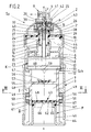
- the dispenser Sp containing the liquid spray device according to the invention is designed as an elongated, essentially cylindrical free-standing device, consisting of a housing 1, a removable head piece 2 and a handle 3. The latter is used to actuate an air pump P.
- the air pump handle 3 sits on the end of the housing 1 opposite the head piece 2.
- the air pump P creates an overpressure cushion in the interior of the dispenser.
- This actuates a discharge valve 4 contained in the dispenser by actuating an outlet valve 4 on the head piece side, by this overpressure air cushion loading both the mirror 6 of the liquid 5 and atomizing it by mixing with the liquid jet.
- the liquid jet emerges from a so-called nozzle 7 of a corresponding spray device 8.
- the added air component leads to a dimensionally stable, so-called "dry" spray jet.
- the overpressure cushion building up in the dispenser Sp is generated in a cylinder chamber 9 of the air pump P. From there, the compressed air arrives in a pressure prechamber 10. From here the distribution takes place in the section of the housing 1 which holds the liquid 5 containing cartridge K is used. It is interchangeably assigned to the donor Sp. It has a diameter such that the cartridge-receiving space 11 leaves an evading annular gap 12 on the jacket wall side, so that compressed air connection is present into the head piece 2, that is to say toward the spray device 8.
- the cartridge K is designed in the form of a bottle and consequently merges into a neck 14 at its end facing away from the edge-reinforced base 13.
- the neck 14 arises from the axially approximately drawn-in cover 15 of the cartridge K and has a cylindrical mouth 16.
- the free space of the housing 1 around the neck 14 and also axially above it ends with a holding plate 17. It is perforated. These are openings 18, one of which can be seen in FIG. 1. Via the latter (18), the compressed air gains connection to the dome-shaped interior of the head piece 2, more precisely that Head chamber 2 '. From here, the branching or division takes place in the sense explained above.
- connection on the cartridge side is formed by a plug-in connection nipple 19 starting from the holding plate 17 and indirectly connected to the head piece 2. It overlaps into the cylindrical mouth 16 of the neck 14. So there is a kind of pipe coupling.
- the lower outer edge of the plug connection nipple 19 has a sealing bead 20. Via the plug connection nipple 19, the interior 21 of the cartridge K is connected to the excess air pressure.
- the liquid 5 is prevented from escaping through the mouth 16 of the neck 14 into the cartridge receiving space 11, for example in cases in which the dispenser Sp is used in an upside-down position for spraying.
- the plug-in connection nipple 19 has a liquid barrier that only allows the passage of air.
- it is a relatively thin-walled ring membrane 22. The latter, with its lip edge, which may be pointed, seals and only yields to the air pressure on the jacket wall of a riser pipe 23 which conducts the liquid 5 into the head piece 2.
- the riser pipe 23 starts from the removable head piece 2. It extends in the longitudinal central axis x-x of the dispenser Sp and extends to the bottom 13 of the cartridge K, but leaving a small distance from it (13), so that the liquid can enter the lower end of the riser pipe 23 unhindered.
- the other, upper end of the riser pipe 23 is on a central, downward directed, into the mouth 14 protruding nozzle 24, which is coaxial to a spring chamber 25 arranged above, the wall forming an upwardly open pot continues over a pot edge into a bush part 26 open in the opposite direction, which, concentrically and at a distance from the spring chamber 25, extends one of the Top of the holding plate 17 receives outgoing nipples.
- the latter leaves between its jacket wall and the inner wall of the bushing part 26 an annular channel 28 which is connected to the overpressure air cushion via one or more openings 29.
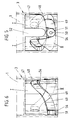
- the edge serving as a cross connection between the wall of the spring chamber 25 and the bush part 26 has openings 30. This also clears the way to the closing outlet valve 4 (cf. FIG. 9).
- the outlet valve 4 consisting of a horizontally embedded annular disk 31 made of elastic material rests on annular walls 32 and 33 arranged concentrically to the longitudinal central axis xx.
- the inner annular wall 33 forming the spring chamber 25 has transverse channels 34. The latter provide the connection between the spring chamber and a circumferential cavity 35 below the washer 31 ago.
- a central shaft 36 This has an annular groove 37 at the level of the annular disk 31. At the bottom of the annular groove there is at least one branch channel 38. The latter connects the liquid and air-permeable annular space section of the spring chamber 25 to a central outlet channel 39 which is connected directly to the transversely outgoing nozzle 7.
- the lower end of the aforementioned shaft 36 extends into the spring chamber 25 and supports the upper end turn of the compression spring 40 loading the outlet valve in the direction of the closed position.
- the other end turn rests on an annular shoulder between the connecting piece 24 and the wall circumscribing the annular chamber 25.
- the outlet valve 4 is actuated via a free-standing spray head pushbutton 41 of the head piece 2 which is spring-loaded in the direction of the closed basic position.
- the upper-side boundary system for the ring disk 31 forms a hat-shaped plug-in part 42, which is held in an annular groove of a cylindrical recess 43 of the head piece 2 and guides the shaft 36 above the ring disk 31.
- the holding plate 17 which brings the plug connection via plug connection nipple 19 to the cartridge K is framed peripherally between the upper end edge 1 'of the housing 1 and the head piece 2 connected to it by screws.
- a centering projection 44 which, despite the elasticity of the material used, since this also has to form the membrane 22, gives the edge section and the entire component a high degree of internal stability.
- a bell-shaped edge 45 with a corresponding internal thread is formed on the rotationally symmetrical head piece 2, which engages in the corresponding external thread of the housing 1.
- the described channel situation in the dispenser head leads to the counter nipple 27 in the head piece 2 being used to form a rotationally symmetrical Y channel, the Y web a of which points to the outlet valve 4, the outer Y leg b via the opening 30 to the head piece.
- the procedure here is further such that the air pump handle 3 is designed as a rotating sleeve which guides the housing 1 of the liquid spraying device and is connected to an air pump piston 46.
- the lower section of the housing 1 merges into a recess 47 which is clearly recognizable from the drawing.
- the offset space 48 remaining through the indentation 47 accommodates the means of a link control that displaces the piston 46.
- the offset space 48 means the space which extends between the cylindrical jacket wall of the recess 47 and the likewise cylindrical inner wall of the handle 3 guided on the housing 1.
- the slim shape of the dispenser is retained.
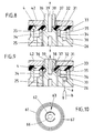
- the link control is formed by two helically rising, raidal inwardly directed open grooves 49. These are located on the inside of the air pump handle 3. They are assigned in a non-overlapping manner and each work with a fixed, radially outwardly directed guide pin 50 of the housing 1 respectively his confiscation 47 together.
- each of the two guide pins 50 arranged in a diametrically opposed position each carry a roller 51.
- the latter can be attached loosely be, since the axially extending inner wall of the handle 3 has a locking effect.
- the same essentially axially aligned insertion shafts 52 are assigned, which in the assembled state, as can be seen from the development in FIG. 7, can be closed with a steeply falling back comb 53.
- the shoulder Sch adjoining the pressure pre-chamber 10 has support ribs 59 formed on the top side, so that between the surface-stable bottom 13 of the cartridge K and the offset housing inner profile passages 60 remain. As a result, the upper edges of the support ribs 59 form the actual annular cartridge shelf in the housing 1.
- the piston 46 of the air pump P carries a piston sleeve 61. It is a hat-shaped body made of elastic material such as rubber or the like. In this respect, it is also suitable for performing a double function, which consists in the piston sleeve 61 simultaneously forming the valve flap 62 of an inlet valve 63 of the pump P seated on the piston 46.
- the piston sleeve 61 is clipped onto the end of a cap 64 which is screwed to the air pump handle 3 and is also cup-shaped and drawn in on the housing side.
- the fastening-side end of the piston 46 forms a corresponding mushroom head, which is gripped behind by an edge bead 61 'on the inner edge of the cup-shaped sleeve.
- valve flap 62 The zone forming the actual valve flap 62 and also the further horizontal surroundings lie flat on the flat underside of the pot base or, better said, the ceiling 65 of the pot-like retraction. In the center of this blanket, which is denoted by 65, there is also a valve opening 66. In the pushed-in end position of the piston 46, the flat top of the sleeve lies flush with the underside of the transverse wall 55, leaving the light gap shown in FIG. 1.
- a further embodiment of the piston sleeve consists in the creation of an end annular space 67.
- the latter has a V-shaped cross section, but can also be a trapezoidal cross section.
- the V opening points in the direction of the flat transverse wall 55.
- the purpose of the peripheral notch is on the one hand to create the cuff-like piston lip, which is undercut, and on the other hand also the creation of a pump limiter. If the pressure in the cartridge receiving space is identical to the pressure in the annular space 67 of the piston 46, further inflation of the cartridge receiving space 11 is no longer possible. In the end of pressure position, the pump piston closes the overflow opening to the cartridge receiving chamber 11 and in this position leaves a compression space.
- the handling and function of the described dispenser is as follows: After pulling off a protective cap 68 covering the head piece 2, the spray head pushbutton 41 is free to exert a compressive force in the direction of the arrow z.
- the housing 1 In order to create or renew or supplement the overpressure cushion required for dispensing the liquid 5, the housing 1 is gripped with one hand; with the other hand, the operator performs reciprocating rotary movements on the handle 3.
- the gate control leads to a superimposed rotary and axial stroke movement of the piston 46.
- the overpressure thus generated is distributed starting from the pressure pre-chamber 10 so that the liquid 5 in the cartridge K is under pressure and compressed air is also present in front of the outlet valve 4. If this is brought into the open position according to FIG. 9, then both components, air plus liquid, enter the outlet channel 39 via the branch channel 38, passing the nozzle 7 with further mixing and forming the desired dimensionally stable jet.
- the compressed air passes through the annular membrane 22, which acts like a lock, but which in turn does not allow any liquid to get into the remaining head chamber 2 'when the dispenser is in a tilted position.
- the overpressure rises the elastic counter-nipple 27 from the corresponding inner wall of the socket part 26.
- the spray jet can be interrupted as soon as the spray device 8 or the spray head pushbutton 41 is released, which, due to the restoring force of the spring 40, returns to its closed starting position.
- the scenery parts circumscribing the groove can be created as individual pieces or at least one of the two parts of the handle 3 can be molded in the same way. In the exemplary embodiment, this is the upper part I.
- the lower part II is therefore fastened in the classic manner. All individual parts can be injection molded from plastic; only the compression spring 40 is made of stainless steel.
- the container section of the cartridge K can be designed as a sack, but the cover 15, also having the neck shape described, is designed as a hard part which is connected to the edge of the sack.
- the bag bottom is also stiffened so that the passages 60 do not become clogged.
Abstract
Description
Die Erfindung bezieht sich auf eine Flüssigkeitssprühvorrichtung gemäß Oberbegriff des Patentanspruches 1.The invention relates to a liquid spray device according to the preamble of
Eine Flüssigkeitssprühvorrichtung dieser Art ist durch die GB-A-299 280 bekannt. Die einer Fahrradpumpe vergleichbare Luftpumpe befindet am einem Kopfstück gegenüberliegenden Ende des Gehäuses der Flüssigkeitssprühvor richtung. Das Kopfstück, eine Düse, ist abschraubbar zugeordnet. Die Flüssigkeit ist dem Gehäuse der Flüssigkeitssprühvorrichtung in nachfüllbarer Weise über einen seitlichen Nippel zuzuordnen oder sie wird durch ein dottersack-ähnlich seitlich zugeordnetes Schraubgefäß bereitgehalten. Insoweit besteht hier eine Schraubgefäß-Nachbestückung. Die so exponierte Lage des Schraubgefäßes ist nicht nur ein Handhabungshindernis; sie läßt das Schraubgefäß auch weitgehend ungeschützt. Der Luftüberdruck wird über eine bypaßartige Außenleitung in das Gehäuse geleitet unter Bildung eines Überdruck-Luftpolters, welches die Flüssigkeit über einen Flüssigkeitsspiegel ausdrückt und mit einer Abzweigung den Flüssigkeitsstahl in der abschraubbaren Düse zerstäubt. Diese Flüssigkeitssprühvorrichtung ist im übrigen fertigungsauswendig und in der Bedienung umständlich, zumal das Auslaßventil als auf der Außenleitung sitzender Absperrhahn gestaltet ist.A liquid spray device of this type is known from GB-A-299 280. The air pump comparable to a bicycle pump is located on a head piece opposite the end of the housing of the liquid spray device. The head piece, a nozzle, can be unscrewed. The liquid can be assigned to the housing of the liquid spraying device in a refillable manner via a lateral nipple or it is held ready by a screw vessel which is laterally assigned to a yolk sac. To this extent, there is a screw vessel refitting. The exposed position of the screw vessel is not just an obstacle to handling; it also leaves the screw vessel largely unprotected. The excess air pressure is passed through a bypass-type outer line into the housing to form an excess pressure air cushion which expresses the liquid via a liquid level and atomizes the liquid steel in the screw-off nozzle with a branch. This liquid spraying device is otherwise difficult to manufacture and laborious to operate, especially since the outlet valve is designed as a shut-off valve sitting on the outer line.
Eine Flüssigkeitssprühvorrichtung dieser Art ist auch durch die US-A-4 167 941 bekannt. Die Luftpumpe wird dort über eine kopfstückseitige Handhabe betätigt. Das sich dabei aufbauende Überdruck-Polster liegt als Speicherkraft vor. Durch Betätigung eines kopfstückseitigen Ausgabeventils wird die Flüssigkeit ausgedrückt. Dabei kommt es zu einem Zerstäuben des Flüssigkeitsstrahles durch Vermischen der Flüssigkeit mit der Druckluft. Die Speisung erfolgt gemäß Fig. 17 aus zwei Quellen. Die Speichereinrichtung besteht in beiden Fällen aus einer Kammer mit frei darin geführter Kolbenscheibe, welche auf einer Druckfeder ruht, die sich mit zunehmender Anfüllung der jeweiligen Kammer entsprechend zunehmend spannt. Der Aufbau des Überdruck-Polsters erfolgt über mehrere kleine Kolben unter Anwendung einer Drehbewegung der besagten Handhabe. Die quer zur Längsmittelachse der Flüssigkeitssprühvorrichtung radial sowie gegenläufig angeordneten Kolben greifen dazu mit ihrem Kolbenschaft über einen Steuerzapfen in einen Zick-Zack-förmigen Kulissenschlitz ein, der, unter Berücksichtigung der Drehbarkeit des Spenderkopfes, einer wellenförmigen Kreisbahn folgt. Das erfordert eine Menge "Dreharbeit". Außerdem liegt eine nicht unerhebliche Schwergängigkeit vor, dies aufgrund ungünstiger Ausrichtung der in enger Folge vorgesehenen sternförmigen Abschnitte der Kulissenführung. Der entsprechende Aufbau ist daher recht kompliziert.A liquid spray device of this type is also known from US-A-4 167 941. The air pump is operated there via a handle on the head piece. The overpressure cushion that builds up is available as a storage force. The liquid is squeezed out by actuating a dispensing valve on the head piece side. The liquid jet is atomized by mixing the liquid with the compressed air. 17 is supplied from two sources. In both cases, the storage device consists of a chamber with a piston disk guided freely therein, which rests on a compression spring which correspondingly tightens with increasing filling of the respective chamber. The overpressure cushion is built up via several small pistons using a rotary movement of the said handle. The pistons, which are arranged radially and in opposite directions transversely to the longitudinal center axis of the liquid spraying device, engage with their piston shaft via a control pin in a zigzag-shaped link slot which, taking into account the rotatability of the dispenser head, follows an undulating circular path. That requires a lot of "shooting". In addition, there is a not inconsiderable stiffness due to the unfavorable alignment of the star-shaped sections of the link guide provided in close succession. The corresponding structure is therefore quite complicated.
Aufgabe der vorliegenden Erfindung ist es, eine gattungsgemäße Flüssigkeitssprühvorrichtung in herstellungstechnisch einfacher, gebrauchsvorteilhafter Weise so auszubilden, daß - selbst unter Anwendung des Wechselkartuschen-Prinzips - ohne Federn erfordernde Abspeicherung ein starker, sogenannter "trockener" Sprühstrahl erreicht wird.The object of the present invention is to manufacture a generic liquid spray device simple, advantageous use so that - even using the interchangeable cartridge principle - a strong, so-called "dry" spray jet is achieved without the need for springs.
Gelöst ist diese Aufgabe durch die im Anspruch 1 angegebene Erfindung.This object is achieved by the invention specified in
Die Unteransprüche sind vorteilhafte Weiterbildungen der erfindungsgemäßen Flüssigkeitssprühvorrichtung.The subclaims are advantageous developments of the liquid spray device according to the invention.
Zufolge solcher Ausgestaltung ist eine gattungsgemäße Flüssigkeitssprühvorrichtung realisiert, die sich durch einfachen Aufbau und einwandfreie Funktion auszeichnet. Ohne besondere Federkörper (vergl. US-A-4 167 941) wird unter Beibehaltung des gewohnten Volumenanteils für die eigentliche Spendermechanik ein stabiles Sprühstrahlprofil erreicht, so daß die unterschiedlichsten Medien ausgebracht werden können, und vor allem das umweltfreundlichere Kartuschensystem mit Vorteil anwendbar wird. Erreicht ist dies alles dadurch, daß der Raum ein Kartuschen- Aufnahmeraum ist, der mantelwandseitig einen Ringspalt als Druckluftanschluß bis in das Kopfstück hinein aufweist. Das Betriebsmedium kann also in ohnehin vorhandenen Spalten und Räumen gespeichert werden, dies vor allem unter Einbeziehung des die Kartusche aufnehmenden Raumes. Hinzu kommt der Kopfbereich, also der im Kopfstück zur Verfügung stehende Raum. Dabei sitzt das das entsprechende Überdruck-Luftpolster schaffende Aggregat in betätigungsgünstigerweise am dem Kopfstück abgewandten Ende. Letzteres bleibt daher bequem abnehmbar für das Einführen der nächsten, vollen Kartusche bzw. die Entnahme der leergewordenen Kartusche. Weiter erweist es sich als vorteilhaft, daß in den Kartuschen-Aufnahmeraum ein am Kopfstück angeordneter Steckanschlußnippel ragt, durch welchen das Innere der Kartusche mit dem Luftdruck verbunden ist. Es kommt so zu einer ausgewogenen Verteilung des Überdruck-Luftpolsters, wobei ein Teil das Anheben bzw. Herbeibringen der Flüssigkeit bewirkt und der andere Anteil für eine überraschend gute Zerstäubung sorgt. Um die entsprechende Funktion auch dann betriebssicher aufrechterhalten zu können, wenn mit nach unten gerichtetem Kopf gearbeitet werden soll, wird weiter vorgeschlagen, daß der Steckanschlußnippel eine Flüssigkeitssperre aufweist. Die Flüssigkeit selbst wird also an einem ungewollten Austritt in das umgebende Überdruck-Polster gehindert, wohingegen aber die Luft selbst über den Steckanschlußnippel in den Innenraum der Kartusche gelangt. Konkret ist eine solche Flüssigkeitssperre mit einfachen Mitteln dadurch erreicht, daß die Flüssigkeitssperre von einer Ringmembran des Steckanschlußnippels gebildet ist, welche mit ihrem Lippenrand dichtend auf der Mantelwand eines die Flüssigkeit in das Kopfstück leitenden Steigrohres aufliegt. Der entsprechende Lippenrand im Verein mit genügend flexiblem Material eines solchen Stecknippels wirkt äußerst feinfühlig; es bedarf daher nicht der separaten Ausbildungen einer solchen Membran. Weiter wird vorgeschlagen, daß die Luftpumpen-Handhabe als sich auf dem Gehäuse der Flüssigkeitssprühvorrichtung führende Drehhülse ausgebildet ist, welche mit einem Luftpumpen-Kolben verbunden ist, der in einer im Gehäuse liegenden Zylinderkammer läuft. Es wird also hier in vorteilhafterweise die äußere Gestalt des Gehäuses als Führungsmittel für die Drehhülse genutzt und der innere Bereich für die Zuordnung und Ausbildung der Zylinderkammer. Das führt zu einer baulich besonders einfachen Lösung. Weiter ist eine vorteilhafte Ausgestaltung erreicht durch eine Kulissensteuerung der Funktionseinheit Kolben/Luftpumpen-Handhabe. Überdies wird vorgeschlagen, daß die Zylinderkammer von einer Einziehung des Gehäuses gebildet ist und im verbleibenden Vorratsraum die Mittel der Kulissensteuerung untergebracht sind. Das erhält der gattungsgemäßen Flüssigkeitsvorrichtung die gewohnte schlanke Form, wobei noch ein weitergehender Vorteil erreicht wird insofern, als die durch die Einziehung gebildete Schulter als Kartuschen-Stellboden benutzt werden kann, wobei zufolge belassender Durchlässe an dieser Schulter der Strömungsweg offengehalten ist. Im Hinblick auf die Kulissensteuerung ist weiter konkret so vorgegangen, daß diese von ansteigenden Nuten an der Innenseite der Luftpumpen-Handhabe gebildet ist, in welche Nuten je ein ortsfester, radialer Führungszapfen des Gehäuses als sogenannter Gleitstein eingreift. Solche Zapfen lassen sich spritztechnisch gleich mitberücksichtigen. Um eine besonders leichtgängige Kulissenführung zu erzielen, sind die Führungszapfen rollenbestückt. Weiter wird vorgeschlagen, daß den Nuten im wesentlichen axiale Einführschächte zugeordnet sind, die in montiertem Zustand durch einen steil abfallenden Rückenkamm des einen Kulissenteils gesperrt ist. Das führt zu einer einwandfreien Zuordnung der den überlagernden Axial/Drehhub des Kolbens bringenden Mittel. Überdies ist eine vorteilhafte Ausbildung erreicht durch einen in der Endphase der Pumpbewegung flacheren Verlauf der ansteigenden Nuten, die überdies in beiden Enden Stütztaschen für die Führungszapfen formen. Einerseits ergibt sich eine erleichterte Betätigung, indem gerade bei erhöhtem Widerstand die flacher ansteigende Zone vorliegt. Die Stütztaschen definieren die Endstellungen, so daß ein Steigungswinkel für die Nuten anwendbar ist, der weit außerhalb der Selbstsperrung liegt. Die endliche Begrenzung der Nuten liegt auf einem Arbeitshub von ca. 135°. Hieraus folgert eine bequeme Bedienungsweise, da die Betätigungshand nicht über Gebühr beansprucht wird, also den ergonomischen Verhältnissen Rechnung getragen ist. Eine günstige Maßnahme liegt ferner darin, daß die Zylinderkammer eine kartuschenseitig das Pumpenventil tragende Querwand besitzt, welche die Einziehung gegenüber dem Kartuschenaufnahmeraum des Gehäuses unter Bildung einer Druck-Vorkammer abteilt. Diese zentral liegende Druck-Vorkammer führt zu einer gleichmäßigen Verteilung des Überdruck-Luftpolsters in einer der Druckquelle sprich Druckpumpe unmittelbar nachgeschalteten Zone. Überdies bringt die Erfindung in Vorschlag, daß der Luftpumpen-Kolben eine Kolbenmanschette mit stirnseitigem Ringraum trägt. Ein solcher Ringraum liegt zweckmäßig im Randbereich der Manschette, führt also einerseits zu der hochelastischen bzw. flexiblen manschettentypischen Kolbenlippe und andererseits zu einem stabilen Übergang zum restlichen Mittelbereich der als Topf oder Teller gestalteten Manschette. Eine darüber hinausgehende Funktion übernimmt die Kolbenmanschette insofern, als diese zugleich den Ventillappen eines Einlaßventiles der Zylinderkammer bildet und auf das topfförmige, gehäuseseitig eingezogene Ende eine mit der Luftpumpen-Handhabe schraubverbundenen Kappe satt aufgeklipst ist. Auf diese Weise setzt sich der Kolben als innerer Schenkel eines rotationssymmetrischen, das untere Ende des Gehäuses umgreifenden U-Profiles der Handhabe fort. Überdies wird vorgeschlagen, daß der Steckanschlußnippel einer perforierten Halteplatte zentral angeformt ist, die zwischen dem oberen Stirnende des Gehäuses und dem damit schraubverbundenen Kopfstück randgefaßt ist und sich in einen mit dem Kopfstück steckverbundenen Gegennippel fortsetzt. Hieraus erwächst nicht nur eine hohe Gesamtstabilität der Halteplatte, sondern auch eine zufriedenstellende Gebrauchsstabilität für beide in Gegenrichtung zueinander verlaufende Nippel, was auch im Hinblick auf die stecktechnische Zuordnung des Kopfstückes von Bedeutung ist. Dabei erweist es sich weiter als nützlich, daß der Gegennippel im Kopfbereich zur Bildung eines rotationssymmetrischen Y-Kanales mit herangezogen ist, dessen Y-Steg zum Ausgabeventil führt und der äußere Y-Schenkel über einen Querkanal an eine Kopfstückkammer anschließt, die sich oberhalb des Kartuschen-Aufnahmeraumes erstreckt. Bei einstehender Kartusche verbleibt durch die zentrierende Wirkung des Steckanschlußnippels ein gleichmäßiger Ringraum zwischen der Mantelwand der Kartusche und der Innenwandung des Gehäuses. Schließlich besteht noch ein vorteilhaftes Merkmal darin, daß das Auslaßventil von einer in Richtung der Schließgrundstellung federbelasteten Sprühkopf-Drucktaste betätigbar ist. Endlich besteht noch eine günstige Ausgestaltung durch einen stirnseitigen Ringraum der Kolbenmanschette als Pumpbegrenzer. Wenn der Druck im Kartuschen-Aufnahmeraum identisch ist mit dem Druck im stirnseitigen Ringraum des Kolbens bei dessen eingefahrener Endstellung ist ein weiteres Aufpumpen des Kartuschen-Aufnahmeraumes etc. nicht mehr möglich. Demzufolge ist auch die Gebrauchssicherheit der beschriebenen Flüssigkeitssprühvorrichtung optimal.As a result of such an embodiment, a generic liquid spray device is realized which is characterized by a simple structure and perfect function. Without a special spring body (cf. US-A-4 167 941), while maintaining the usual volume fraction for the actual dispenser mechanism, a stable spray jet profile is achieved, so that the most varied of media can be applied, and above all the more environmentally friendly cartridge system can be used with advantage. All of this is achieved in that the space is a cartridge receiving space which has an annular gap on the jacket wall side as a compressed air connection right into the head piece. The operating medium can therefore be stored in columns and rooms that are already present, above all taking into account the space accommodating the cartridge. In addition, there is the head area, i.e. the space available in the head piece. The unit that creates the corresponding overpressure air cushion sits in the end conveniently remote from the head piece. The latter therefore remains easily removable for the insertion of the next, full cartridge or the removal of the empty cartridge. Furthermore, it proves to be advantageous that a plug connection nipple arranged on the head piece projects into the cartridge receiving space, through which the inside of the cartridge is connected to the air pressure. This results in a balanced distribution of the overpressure air cushion, one part causing the liquid to be raised or brought in and the other part ensuring surprisingly good atomization. In order to be able to maintain the corresponding function in a reliable manner even when working with the head directed downward, it is further proposed that the plug-in connection nipple has a liquid lock. The liquid itself is thus prevented from unintentionally escaping into the surrounding overpressure cushion, whereas the air itself reaches the interior of the cartridge via the plug connection nipple. Specifically, such a liquid barrier is achieved with simple means in that the liquid barrier is formed by an annular membrane of the plug-in connection nipple, which rests with its lip edge sealingly on the jacket wall of a riser pipe conducting the liquid into the head piece. The corresponding lip rim in combination with enough flexible material of such a plug nipple appears extremely sensitive; separate formations of such a membrane are therefore not required. It is further proposed that the air pump handle is designed as a rotating sleeve which guides itself on the housing of the liquid spray device and is connected to an air pump piston which runs in a cylinder chamber located in the housing. The outer shape of the housing is advantageously used here as a guide means for the rotating sleeve and the inner area for the assignment and design of the cylinder chamber. This leads to a structurally particularly simple solution. Furthermore, an advantageous embodiment is achieved by controlling the linkage of the piston / air pump handle functional unit. It is also proposed that the cylinder chamber of a retraction of the housing is formed and the means of the gate control are accommodated in the remaining storage room. This gives the generic liquid device the usual slim shape, whereby a further advantage is achieved in that the shoulder formed by the retraction can be used as a cartridge shelf, whereby the flow path is kept open on this shoulder due to the passage openings. With regard to the gate control, the procedure is further specifically such that it is formed by rising grooves on the inside of the air pump handle, into which grooves a stationary, radial guide pin of the housing engages as a so-called sliding block. Such cones can also be taken into account in the injection molding process. The guide pins are fitted with rollers in order to achieve a particularly smooth sliding guide. It is further proposed that the grooves are assigned essentially axial insertion shafts, which in the assembled state are blocked by a steeply sloping back comb of the one link part. This leads to a correct allocation of the means bringing the superimposing axial / rotary stroke of the piston. In addition, an advantageous embodiment is achieved by a flatter course of the rising grooves in the final phase of the pumping movement, which also form support pockets for the guide pins in both ends. On the one hand, there is an easier actuation in that the flat rising zone is present, especially when there is increased resistance. The support pockets define the end positions, so that a pitch angle for the grooves is applicable, which is far outside the self-locking. The finite limitation of the grooves lies on a working stroke of approx. 135 °. This results in a convenient mode of operation, since the operating hand is not overused, i.e. the ergonomic one Conditions is taken into account. A favorable measure also lies in the fact that the cylinder chamber has a transverse wall carrying the pump valve on the cartridge side, which divides the retraction with respect to the cartridge receiving space of the housing to form a pressure prechamber. This centrally located pressure pre-chamber leads to an even distribution of the overpressure air cushion in a zone immediately downstream of the pressure source, ie pressure pump. In addition, the invention proposes that the air pump piston carries a piston sleeve with an end annular space. Such an annular space expediently lies in the edge area of the sleeve, thus leading on the one hand to the highly elastic or flexible sleeve lip typical of the sleeve and on the other hand to a stable transition to the remaining central area of the sleeve designed as a pot or plate. The piston sleeve assumes a further function insofar as it also forms the valve tab of an intake valve of the cylinder chamber and a cap screwed to the air pump handle is clipped onto the pot-shaped end drawn in on the housing side. In this way, the piston continues as the inner leg of a rotationally symmetrical U-profile of the handle, which surrounds the lower end of the housing. In addition, it is proposed that the plug connection nipple of a perforated holding plate is formed centrally, which is framed between the upper front end of the housing and the screw-connected head piece and continues into a counter-nipple plug-connected to the head piece. This results not only in a high overall stability of the holding plate, but also a satisfactory usage stability for both nipples running in opposite directions to one another, which is also important with regard to the technical assignment of the head piece is. It also proves useful that the counter nipple is used in the head area to form a rotationally symmetrical Y-channel, the Y-web of which leads to the dispensing valve and the outer Y-leg connects via a transverse channel to a headpiece chamber which is located above the cartridge - Recording room extends. When the cartridge is in place, the centering effect of the plug connection nipple leaves a uniform annular space between the jacket wall of the cartridge and the inner wall of the housing. Finally, there is an advantageous feature that the outlet valve can be actuated by a spray head pushbutton which is spring-loaded in the direction of the closed basic position. Finally, there is still a favorable configuration through an end annular space of the piston sleeve as a pump limiter. If the pressure in the cartridge receiving space is identical to the pressure in the end annular space of the piston when the piston is in its retracted end position, it is no longer possible to inflate the cartridge receiving space etc. As a result, the safety of use of the liquid spray device described is also optimal.
Der Gegenstand der Erfindung ist nachstehend anhand eines zeichnerisch veranschaulichten Ausführungsbeispieles näher erläutert. Es zeigt:
- Fig. 1
- die als sogenannter Spender ausgebildete erfindungsgemäße Flüssigkeitssprühvorrichtung im Vertikalschnitt, und zwar bei in eingefahrener Endstellung befindlichem Pumpenkolben,
- Fig. 2
- eine der Fig. 1 entsprechende Darstellung, jedoch bei in die entgegengesetzte Endstellung ausgefahrenem Pumpenkolben,
- Fig. 3
- den Schnitt gemäß Linie III-III in Fig. 2,
- Fig. 4
- den bodenseitigen Abschnitt der Flüssigkeitssprühvorrichtung unter Verdeutlichung der Kulissensteuerungsmittel, in perspektiver Darstellung,
- Fig. 5
- eine Ansicht in Richtung des Pfeiles V in Fig. 4, aber bei zurückgefahrenem Kolben,
- Fig. 6
- eine Ansicht hierzu um ca. 90° nach links versetzt,
- Fig. 7
- eine Abwicklung der Kulissensteuerungs-Nuten,
- Fig. 8
- eine Herausvergrößerung des Auslaßventils in Schließstellung,
- Fig. 9
- eine solche in Öffnungsstellung aufgrund Betätigung der Sprühkopf-Drucktaste und
- Fig. 10
- die Draufsicht auf den Pumpenkolben.
- Fig. 1
- the liquid spray device according to the invention, designed as a so-called dispenser, in vertical section, specifically with the pump piston in the retracted end position,
- Fig. 2
- 1 corresponding representation, but with the pump piston extended into the opposite end position,
- Fig. 3
- the section along line III-III in Fig. 2,
- Fig. 4
- the bottom section of the liquid spray device with clarification of the link control means, in a perspective view,
- Fig. 5
- 4 shows a view in the direction of arrow V in FIG. 4, but with the piston retracted,
- Fig. 6
- a view of this is offset by about 90 ° to the left,
- Fig. 7
- a development of the slide control grooves,
- Fig. 8
- an enlargement of the exhaust valve in the closed position,
- Fig. 9
- such in the open position due to actuation of the spray button and
- Fig. 10
- the top view of the pump piston.
Der die erfindungsgemäße Flüssigkeitssprühvorrichtung enthaltende Spender Sp ist als längliches, im wesentlichen zylindrisches Standgerät konzipiert, bestehend aus einem Gehäuse 1, einem abnehmbaren Kopfstück 2 und einer Handhabe 3. Letztere dient zur Betätigung einer Luftpumpe P.The dispenser Sp containing the liquid spray device according to the invention is designed as an elongated, essentially cylindrical free-standing device, consisting of a
Die Luftpumpen-Handhabe 3 sitzt am dem Kopfstück 2 gegenüberliegenden Ende des Gehäuses 1.The air pump handle 3 sits on the end of the
Unter hin- und hergehender Drehbewegung der Handhabe 3 erzeugt die Luftpumpe P im Spenderinneren ein Überdruck-Polster. Dieses bewirkt unter Betätigung eines kopfstückseitigen Auslaßventils 4 den Austritt einer im Spender enthaltenen Flüssigkeit 5, indem dieses Überdruck-Luftpolster sowohl den Spiegel 6 der Flüssigkeit 5 belastet als auch durch Vermischen mit dem Flüssigkeitsstrahl diesen zerstäubt. Der Flüssigkeitsstrahl tritt aus einer sogenannten Düse 7 einer entsprechenden Sprüheinrichtung 8 aus. Die hinzukommende Luftkomponente führt zu einen formstabilen, sogenannten "trockenen" Sprühstrahl.While the
Erzeugt wird das im Spender Sp sich aufbauende Überdruck-Polster in einer Zylinderkammer 9 der Luftpumpe P. Von dort gelangt die Druckluft in eine Druck-Vorkammer 10. Von hier aus erfolgt die Verteilung in den Abschnitt des Gehäuses 1, der zur Aufnahme einer die Flüssigkeit 5 enthaltenden Kartusche K dient. Sie ist dem Spender Sp auswechselbar zugeordnet. Sie weist einen derartigen Durchmesser auf, daß der Kartuschen-Aufnahmeraum 11 mantelwandseitig einen ausweichenden Ringspalt 12 beläßt, so daß Druckluftanschluß bis in das Kopfstück 2 hinein, also zur Sprüheinrichtung 8 hin, vorliegt.The overpressure cushion building up in the dispenser Sp is generated in a
Die Kartusche K ist in Form einer Flasche gestaltet und geht demzufolge an ihrem dem randverstärkten Boden 13 abgewandten Ende in einen Hals 14 über. Der Hals 14 entspringt der axial etwa eingezogenen Decke 15 der Kartusche K und besitzt eine zylindrische Mündung 16.The cartridge K is designed in the form of a bottle and consequently merges into a
Der um den Hals 14 und auch axial darüber verbleibende Freiraum des Gehäuses 1 schließt mit einer Halteplatte 17 ab. Diese ist perforiert. Es handelt sich um Durchbrechungen 18, von-denen eine aus Fig. 1 ersichtlich ist. Über letztere (18) gewinnt die Druckluft Anschluß an den domförmigen Innenraum des Kopfstückes 2, genauer der Kopfstück-Kammer 2'. Von hier aus erfolgt die Verzweigung bzw. Aufteilung im oben erläuterten Sinn.The free space of the
Den kartuschenseitigen Anschluß bildet hierzu ein von der besagten Halteplatte 17 ausgehender, mittelbar mit dem Kopfstück 2 verbundener Steckanschlußnippel 19. Er tritt überlappend in die zylindrische Mündung 16 des Halses 14 ein. So liegt eine Art Rohrkupplung vor. Der untere äußere Rand des Steckanschlußnippels 19 besitzt einen Dichtungswulst 20. Über den Steckanschlußnippel 19 ist das Innere 21 der Kartusche K so mit dem Luftüberdruck verbunden.For this purpose, the connection on the cartridge side is formed by a plug-in
Andererseits ist aber die Flüssigkeit 5 daran gehindert, über die Mündung 16 des Halses 14 in den Kartuschen-Aufnahmeraum 11 auszutreten, beispielsweise in Fällen, in denen der Spender Sp in auf dem Kopf stehender Lage zum Sprüheinsatz kommt. Erreicht ist das dadurch, daß der Steckanschlußnippel 19 eine nur den Luftdurchlaß erlaubende Flüssigkeitssperre aufweist. Diesbezüglich handelt es sich um eine relativ dünnwandige Ringmembran 22. Letztere liegt mit ihrem gegebenenfalls ausspitzenden Lippenrand dichtend und nur dem Luftdruck nachgebend auf der Mantelwand eines die Flüssigkeit 5 in das Kopfstück 2 leitenden Steigrohres 23.On the other hand, however, the
Das Steigrohr 23 geht vom abnehmbaren Kopfstück 2 aus. Es erstreckt sich in der Längsmittelachse x-x des Spenders Sp und reicht bis zum Boden 13 der Kartusche K, allerdings unter Belassung eines geringen Abstandes dazu (13), so daß die Flüssigkeit ungehindert in das untere Ende des Steigrohres 23 eintreten kann.The
Das andere, obere Ende des Steigrohres 23 steckt auf einem zentralen, nach unten gericheten, bis in die Mündung 14 hineinragenden Stutzen 24, welcher koaxial zu einer darüber angeordneten Federkammer 25 liegt, deren einen nach oben offenen Topf bildende Wandung sich über einen Topfrand in einen in Gegenrichtung offenen Büchsenteil 26 fortsetzt, der, konzentrisch und mit Abstand zur Federkammer 25 verlaufend, einen von der Oberseite der Halteplatte 17 ausgehenden Gegennippel aufnimmt. Letzterer läßt zwischen seiner Mantelwand und der Innenwand des Büchsenteiles 26 einen Ringkanal 28 frei, der über eine oder mehrere Durchbrechungen 29 mit dem Überdruck-Luftpolster in Verbindung steht. Weiter besitzt der als Querverbindung zwischen der Wandung der Federkammer 25 und dem Büchsenteil 26 dienende Rand Durchbrechungen 30. Hierdurch ist auch der Weg frei zum verschließenden Auslaßventil 4 (vgl. Fig. 9).The other, upper end of the
Das von einer horizontal eingelagerten Ringscheibe 31 aus elastischem Material bestehende Auslaßventil 4 ruht auf konzentrisch zur Längsmittelachse x-x angeordneten Ringwänden 32 und 33. Die innen liegende, die Federkammer 25 mitbildende Ringwand 33 besitzt Querkanäle 34. Letztere stellen die Verbindung zwischen Federkammer und einer umlaufenden Höhlung 35 unterhalb der Ringscheibe 31 her.The
Ein weiteres Bestandteil des Auslaßventils 4 ist ein zentraler Schaft 36. Dieser weist auf Höhe der Ringscheibe 31 eine Ringnut 37 auf. Auf dem Grund der Ringnut befindet sich mindestens ein Stichkanal 38. Letzterer verbindet den flüssigkeits- und luftdurchsetzten Ringraumabschnitt der Federkammer 25 mit einem zentralen Auslaßkanal 39, welcher direkt mit der quer abgehenden Düse 7 verbunden ist.Another component of the
Das untere Ende des erwähnten Schaftes 36 reicht in die Federkammer 25 hinein und stützt dort die obere Endwindung der das Auslaßventil in Richtung der Schließstellung belastenden Druckfeder 40. Deren andere endständige Windung ruht auf einer Ringschulter zwischen den Stutzen 24 und der die Ringkammer 25 umschreibenden Wandung.The lower end of the
Die Betätigung des Auslaßventils 4 geschieht über eine freistehend angeordnete, in Richtung der Schließgrundstellung federbelastete Sprühkopf-Drucktaste 41 des Kopfstückes 2.The
Die oberseitige Begrenzungsanlage für die Ringscheibe 31 bildet ein hutförmiges Steckteil 42, welche sich in einer Ringnut einer zylindrischen Einziehung 43 des Kopfstückes 2 festhält und den Schaft 36 oberhalb der Ringscheibe 31 führt.The upper-side boundary system for the
Die die Steckverbindung via Steckanschlußnippel 19 zur Kartusche K bringende Halteplatte 17 ist peripher zwischen dem oberen Stirnrand 1' des Gehäuses 1 und dem damit schraubverbundenen Kopfstück 2 randgefaßt. Dem randgefaßten Abschnitt der Halteplatte vorgelagert befindet sich ein Zentriervorsprung 44, welcher trotz Elastizität des verwendeten Materiales, da dieses ja auch die Membran 22 bilden muß, der Randpartie und überhaupt dem ganzen Bauteil eine hohe innere Stabilität verleiht.The holding
Zur Ermöglichung der Schraubverbindung ist dem rotationssymmetrisch gestalteten Kopfstück 2 ein glockenförmiger Rand 45 mit entsprechendem Innengewinde angeformt, welches in das korrespondierende Außengewinde des Gehäuses 1 eingreift.To enable the screw connection, a bell-shaped
Die beschriebene Kanalsituation im Spenderkopf führt dazu, daß der Gegennippel 27 im Kopfstück 2 zur Bildung eines rotationssymmetrischen Y-Kanales mitherangezogen ist, dessen Y-Steg a zum Auslaßventil 4 weist, wobei der äußere Y-Schenkel b über die Durchbrechung 30 an die Kopfstück-Kammer 2' anschließt, die sich oberhalb des Kartuschen-Aufnahmeraumes 11 erstreckt.The described channel situation in the dispenser head leads to the
Was nun die Einzelheiten im Hinblick auf die Ausbildung der Pumpe P angeht, so ist hier weiter so vorgegangen, daß die Luftpumpen-Handhabe 3 als sich auf dem Gehäuse 1 der Flüssigkeitssprühvorrichtung führende Drehhülse ausgebildet ist, welche mit einem Luftpumpen-Kolben 46 verbunden ist. Zur Schaffung seiner Zylinderkammer 9 geht der untere Abschnitt des Gehäuses 1 in eine aus der zeichnerischen Darstellung deutlich erkennbare Einziehung 47 über. Der durch die Einziehung 47 verbleibende Versatzraum 48 nimmt die Mittel einer den Kolben 46 verlagernden Kulissensteuerung auf. Als Versatzraum 48 ist der Raum gemeint, welcher sich zwischen der zylindrischen Mantelwand der Einziehung 47 und der ebenfalls zylindrischen Innenwand der auf dem Gehäuse 1 geführten Handhabe 3 erstreckt. Die schlanke Form des Spenders bleibt so erhalten. Gebildet ist die Kulissensteuerung von zwei wendelförmig ansteigenden, raidal einwärts gerichetet offenen Nuten 49. Diese sitzen an der Innenseite der Luftpumpen-Handhabe 3. Sie sind in nicht überlappender Weise zugeordnet und arbeiten mit je einem ortsfesten, radial nach außen gerichteten Führungszapfen 50 des Gehäuses 1 respektive seiner Einziehung 47 zusammen.As far as the details with regard to the design of the pump P are concerned, the procedure here is further such that the air pump handle 3 is designed as a rotating sleeve which guides the
Beide in diametraler Gegenüberlage angeordnete Führungszapfen 50 tragen im Interesse der Reduzierung der Reibkräfte je eine Rolle 51. Letztere können lose aufgesteckt sein, da die sich axial davor erstreckende Innenwandung der Handhabe 3 sperrend wirkt. Einerseits zur Erleichterung der Montage und andererseits zur Schaffung möglichst in Umfangsrichtung winkelgroßer Nuten sind denselben im wesentlichen axial ausgerichtete Einführschächte 52 zugeordnet, welche sich in montiertem Zustand, wie aus der Abwicklung Fig. 7 ersichtlich, mit einem steil abfallenden Rückenkamm 53 verschließen lassen.In the interest of reducing the frictional forces, each of the two guide pins 50 arranged in a diametrically opposed position each carry a
Der Kurvenverlauf der beiden Nuten 49 ist im übrigen so gewählt, daß in der Endphase der Pumpbetätigung d. h. der Kompression der flacher ansteigende Abschnitt zur Steuerung kommt. Mit zunehmendem Kompressionsdruck in der Zylinderkammer 9 der Luftpumpe P ergibt sich eine zunehmendere Leichtgängigkeit, die in der steileren Phase aufgrund der Anfangskompression gleichwohl bequem durchlaufen wird. Durch in den Enden der Nuten 49 belassene Stütztaschen 54 ergibt sich eine gewisse Rast- bzw. Feststellwirkung, so daß einer Selbstverstellung der Handhabe 3 beispielsweise aufgrund zufälliger Berührungen etc. in der Utensilientasche entgegengewirkt ist.The course of the curve of the two
Die Unterteilung der Einziehung 47 in die beschriebene Zylinderkammer 9 und die sich davor erstreckende Druck-Vorkammer 10 erfolgt über eine dem Gehäuse 1 gleich angeformte Querwand 55. An dieser befindet sich kartuschenseitig ein Pumpenventil 56. Es besteht aus einem freigeschnittenen Ventillappen, der in einer Fassung eingelassen ist und die zentral liegende Ventilöffnung 57 in der Querwand 55 von oben her abdeckt.The subdivision of the
Der sich an die Druck-Vorkammer 10 anschließende Schulter Sch weist oberseitig angeformte Stützrippen 59 auf, so daß zwischen dem flächenstabilen Boden 13 der Kartusche K und dem versetzten Gehäuseinnenprofil Durchlässe 60 verbleiben. Demzufolge bilden die Oberkanten der Stützrippen 59 den eigentlichen, ringförmigen Kartuschen-Stellboden im Gehäuse 1.The shoulder Sch adjoining the
Der Kolben 46 der Luftpumpe P trägt eine Kolbenmanschette 61. Es handelt sich um einen hutförmigen Körper aus elastischem Material wie Gummi oder dergleichen. Sie ist insoweit auch geeignet, eine Doppelfunktion zu übernehmen, die darin besteht, daß die Kolbenmanschette 61 zugleich den Ventillappen 62 eines am Kolben 46 sitzenden Einlaßventils 63 der Pumpe P bildet. Die Kolbenmanschette 61 ist auf das selbst ebenfalls topfförmig gestaltete, gehäuseseitig eingezogene Ende einer mit der Luftpumpen-Handhabe 3 schraubverbundenen Kappe 64 aufgeklipst. Das befestigungsseitige Ende des Kolbens 46 formt einen entsprechenden Pilzkopf, welcher mittels einer Randwulst 61' am inneren Rand der topfförmigen Manschette hintergriffen ist. Die den eigentlichen Ventillappen 62 bildende Zone und auch das weitere horizontale Umfeld liegt flach auf der ebenen Unterseite des Topfbodens oder besser gesagt der Decke 65 der topfartigen Einziehung auf. Im Zentrum dieser mit 65 bezeichneten Decke liegt auch hier eine Ventilöffnung 66. In eingeschobener Endstellung des Kolbens 46 liegt die ebene Oberseite der Manschette ebenengleich an der Unterseite der Querwand 55 an, unter Belassung des aus Fig. 1 ersichtlichen Lichtspaltes.The
Eine weitere Ausgestaltung der Kolbenmanschette besteht in der Schaffung eines stirnseitigen Ringraumes 67. Letzterer weist V-förmigen Querschnitt auf, kann aber auch trapezförmigen Querschnitts sein. Die V-Öffnung weist in Richtung der ebenen Querwand 55. Sinn und Zweck der peripheren Kerbung ist zum einen die Schaffung der manschettentypischen Kolbenlippe, welche hinterschnitten ist, und zum anderen aber auch die Schaffung eines Pumpbegrenzers. Wenn der Druck im Kartuschen-Aufnahmeraum identisch ist mit dem Druck im Ringraum 67 des Kolbens 46, ist ein weiteres Aufpumpen des Kartuschen-Aufnahmeraumes 11 nicht mehr möglich. Der Pumpenkolben schließt in Druckendstellung die Überströmöffnung zur Kartuschen-Aufnahmekammer 11 hin ab und beläßt in dieser Stellung einen Kompressionsfreiraum.A further embodiment of the piston sleeve consists in the creation of an end
Die Handhabung und Funktion des beschriebenen Spenders ist wie folgt:
Nach Abziehen einer das Kopfstück 2 überfangenden Schutzkappe 68 liegt die Sprühkopf-Drucktaste 41 zur Ausübung einer Druckkraft in Richtung des Pfeiles z frei.The handling and function of the described dispenser is as follows:
After pulling off a
Um das für das Ausbringen der Flüssigkeit 5 erforderliche Überdruck-Polster zu schaffen oder zu erneuern bzw. zu ergänzen, wird das Gehäuse 1 mit der einen Hand erfaßt; mit der anderen Hand führt der Bedienende hin- und hergehende Drehbewegungen an der Handhabe 3 aus. Die Kulissensteuerung führt zu einer überlagernden Dreh- und Axialhub-Bewegung des Kolbens 46. Der so erzeugte Überdruck verteilt sich ausgehend von der Druck-Vorkammer 10 so, daß die Flüssigkeit 5 in der Kartusche K druckbelastet ist und ebenso Druckluft vor dem Auslaßventil 4 ansteht. Wird dieses in die Öffnungsstellung gemäß Fig. 9 gebracht, so treten beide Komponenten, Luft plus Flüssigkeit via Stichkanal 38 in den Auslaßkanal 39, wobei sie unter weiterer Mischung die Düse 7 passieren und den gewünschten formstabilen Strahl bilden. Die Druckluft passiert dabei dazu die wie eine Schleuse wirkende Ringmembran 22, die ihrerseits aber bei in Kipplage befindlichem Spender keine Flüssigkeit in die übrige Kopfkammer 2' kommen läßt. Zum Passieren des Überdrucks hebt sich der elastische Gegennippel 27 von der korrespondierenden Innenwandung des Buchsenteils 26 ab. Der Sprühstrahl kann unterbrochen werden, sobald die Sprüheinrichtung 8 bzw. die Sprühkopf-Drucktaste 41 losgelassen wird, welche zufolge der Rückstellkraft der Feder 40 wieder in ihre Schließausgangsposition zurückfährt.In order to create or renew or supplement the overpressure cushion required for dispensing the
Die die Nut umschreibenden Kulissenteile können als Einzelstücke erstellt sein oder aber mindestens eines der beiden Teile der Handhabe 3 gleichangeformt werden. Beim Ausführungsbeispiel ist dies das obere Teil I. Das untere Teil II wird demzufolge in der klassischen Weise befestigt. Sämtliche Einzelteile lassen sich aus Kunststoff spritzen; lediglich die Druckfeder 40 besteht aus nichtrostendem Stahl.The scenery parts circumscribing the groove can be created as individual pieces or at least one of the two parts of the
Der Behälterabschnitt der Kartusche K kann als Sack ausgebildet sein, wobei aber die Decke 15, auch die beschriebene Halsgestalt aufweisend, als Hartteil gestaltet ist, das mit dem Sackrand verbunden ist. Der Sackboden ist ebenfalls versteift, so daß sich die Durchlässe 60 nicht zusetzen.The container section of the cartridge K can be designed as a sack, but the
Claims (18)
- Liquid spray device with an air pump (P) which is to be operated by a handle (3) and of which the excess pressure air cushion upon operation of an outlet valve (4) on the head piece side forces the liquid (5) out and atomises it by mixing with the liquid jet, wherein between the removable head piece (2) and the air pump handle (3), which is arranged at the opposite end, is located a chamber which can be brought below the excess pressure of air, characterised in that the chamber is a cartridge receiving chamber (11) which on the cylindrical wall side comprises an annular gap (12) as a compressed air connection extending into the head piece (2).
- Liquid spray device according to claim 1, characterised in that into the cartridge receiving chamber (11) extends a push-fit connecting nipple (19) which is arranged on the head piece (2) and by which the interior (21) of the cartridge (K) is connected to the excess air pressure.
- Liquid spray device according to claim 2, characterised in that the push-fit connecting nipple (19) comprises a liquid barrier.
- Liquid spray device according to claim 3, characterised in that the liquid barrier is formed by an annular diaphragm (22) of the push-fit connecting nipple (19) which by its lip edge rests sealingly on the cylindrical wall of an ascending pipe (23) which conducts the liquid (5) into the head piece (2).
- Liquid spray device according to one or more of the preceding claims, characterised in that the air pump handle (3) is constructed as a rotary sleeve which is guided on the housing (1) of the liquid spray device and which is connected to an air pump piston (46) which runs in a cylinder chamber (9) located in the housing (1).
- Liquid spray device according to claim 5, characterised by a link motion (49/50) of the functional unit of piston/air pump handle (9/3).
- Liquid spray device according to either of claims 5 or 6, characterised in that the cylinder chamber (9) is formed by a neck (47) of the housing (1), and in the remaining stowing space (48) are accommodated the means of the link motion (49/50).
- Liquid spray device according to claim 7, characterised in that the shoulder (Sch) formed by the neck (47) serves as a cartridge stand which leaves passages (60).
- Liquid spray device according to any of the preceding claims 6 to 8, characterised in that the link motion is formed by ascending grooves (49) on the inside of the air pump handle (3), in each of which grooves (49) engages a stationary radial guide pin (50) of the housing (1).
- Liquid spray device according to claim 9, characterised in that the guide pins (50) are fitted with rollers, and associated with the grooves (49) are essentially axial insertion shafts (52) which in the assembled state are blocked by a steeply descending back ridge (53) of one link portion.
- Liquid spray device according to either of the preceding claims 9 or 10, characterised by a flatter course of the ascending grooves (49) in the final stage of pump operation, which grooves (49) in both ends form supporting recesses (54) for the guide pins (50).
- Liquid spray device according to one or more of the preceding claims 7 to 11, characterised in that the cylinder chamber (9) has a transverse wall (55) which carries the pump valve (56) on the cartridge side and which partitions off the neck (47) from the cartridge receiving chamber (11) of the housing (1), forming a preliminary pressure chamber (10).
- Liquid spray device according to one or more of the preceding claims, characterised in that the air pump piston (46) carries a piston cup (61) with an annular chamber (67) at the end face.
- Liquid spray device according to claim 13, characterised in that the piston cup (61) also forms the valve flap (62) of an inlet valve (63) of the cylinder chamber (9) and is clipped onto the pot-shaped end of a cap (64) screwed to the air pump handle (3), which end is necked on the housing side.
- Liquid spray device according to one or more of the preceding claims 2 to 14, characterised in that the push-fit connecting nipple (19) is integrally formed centrally with a perforated holding plate (17) which is encompassed at its edge between the upper front end (1') of the housing (1) and the head piece (2) screwed thereto and continues into a counternipple (27) connected by push fit to the head piece (2).
- Liquid spray device according to claim 15, characterised in that the counternipple (27) in the head piece (2) is also used to form a rotationally symmetrical Y-channel of which the Y-stem (a) leads to the outlet valve (4) and the outer Y-arm (b) via an aperture (30) adjoins a head piece chamber (2') which extends above the cartridge receiving chamber (11).
- Liquid spray device according to one or more of the preceding claims, characterised in that the outlet valve (4) can be operated by a spray head push button (41) which is spring-loaded in the direction of the normal closed position.
- Liquid spray device according to one or more of the preceding claims 13 to 17, characterised by an annular chamber (67) of the piston cup (61) at the end face as a pump limiter.
Applications Claiming Priority (2)
| Application Number | Priority Date | Filing Date | Title |
|---|---|---|---|
| DE4004653A DE4004653A1 (en) | 1990-02-15 | 1990-02-15 | LIQUID SPRAYING DEVICE |
| DE4004653 | 1990-02-15 |
Publications (3)
| Publication Number | Publication Date |
|---|---|
| EP0442058A2 EP0442058A2 (en) | 1991-08-21 |
| EP0442058A3 EP0442058A3 (en) | 1992-02-19 |
| EP0442058B1 true EP0442058B1 (en) | 1995-01-11 |
Family
ID=6400188
Family Applications (1)
| Application Number | Title | Priority Date | Filing Date |
|---|---|---|---|
| EP90122820A Expired - Lifetime EP0442058B1 (en) | 1990-02-15 | 1990-11-29 | Liquid spray device |
Country Status (7)
| Country | Link |
|---|---|
| US (1) | US5405060A (en) |
| EP (1) | EP0442058B1 (en) |
| AT (1) | ATE116872T1 (en) |
| DE (2) | DE4004653A1 (en) |
| DK (1) | DK0442058T3 (en) |
| ES (1) | ES2066942T3 (en) |
| GR (1) | GR3015745T3 (en) |
Families Citing this family (16)
| Publication number | Priority date | Publication date | Assignee | Title |
|---|---|---|---|---|
| DE4108428A1 (en) * | 1991-03-15 | 1992-09-17 | Wiegner Georg Dipl Kaufm | Dispenser esp. for pressurised fluids - has valve of movable valve disc located in container opening, and includes counter-seal |
| DE4136826A1 (en) * | 1991-11-08 | 1993-05-13 | Pfeiffer Erich Gmbh & Co Kg | DISCHARGE DEVICE FOR MEDIA |
| DE9217250U1 (en) * | 1992-12-17 | 1993-02-11 | Wella Ag, 6100 Darmstadt, De | |
| US6991136B2 (en) * | 2001-11-26 | 2006-01-31 | De La Guardia Mario Felix | Pressurizing device for attachment to fluid containers |
| US20040164083A1 (en) * | 2003-02-26 | 2004-08-26 | Lin Arlo H. T. | Bag for use in gas can |
| KR100782330B1 (en) * | 2006-07-14 | 2007-12-06 | 주식회사 예찬 | Pump dispenser |
| US8177101B1 (en) * | 2007-02-06 | 2012-05-15 | William Sydney Blake | One turn actuated duration spray pump mechanism |
| GB2493352A (en) * | 2011-08-01 | 2013-02-06 | Owen Brown | A sprayer comprising a detachable product module and an air pressurisation apparatus. |
| NL1039048C2 (en) * | 2011-09-17 | 2013-03-25 | Henri Peteri Beheer Bv | SOAP DISPENSER. |
| US9415401B2 (en) | 2012-04-04 | 2016-08-16 | Alternative Packaging Solutions Llc | One turn actuated duration spray pump mechanism |
| US8908896B2 (en) * | 2012-06-29 | 2014-12-09 | Intel Corporation | Earpiece for an electronic device |
| AU2013330959A1 (en) * | 2012-10-19 | 2015-05-07 | Rust-Oleum Corporation | Propellantless aerosol system |
| EP3137226B1 (en) * | 2014-05-22 | 2019-07-10 | Colgate-Palmolive Company | Refill cartridge and system comprising the refill cartridge and a pump dispenser |
| DE202016006615U1 (en) * | 2016-10-26 | 2018-01-30 | WIK - ELEKTROGERÄTE Entwicklungs- und Service-GmbH & Co. KG | Hair styling device for applying a care substance by means of compressed air |
| AR125176A1 (en) | 2020-12-15 | 2023-06-21 | Unilever Global Ip Ltd | SPRAY DISPENSER |
| US20240001382A1 (en) | 2020-12-15 | 2024-01-04 | Conopco, Inc., D/B/A Unilever | Spray dispenser |
Family Cites Families (30)
| Publication number | Priority date | Publication date | Assignee | Title |
|---|---|---|---|---|
| US337943A (en) * | 1886-03-16 | Clabence a | ||
| GB189507723A (en) * | 1895-04-17 | 1895-08-31 | Henry Bartz | An Improved Mustard Pot. |
| US1080835A (en) * | 1912-09-20 | 1913-12-09 | George J Kelley | Atomizer. |
| GB179740A (en) * | 1921-03-12 | 1922-05-18 | Charles Alfred Outwin Saxelby | Improvements relating to spraying apparatus |
| GB299280A (en) * | 1928-06-01 | 1928-10-25 | Walter Roy Weeks | Improvements in apparatus for spraying paint, varnish, lacquer or the like |
| US1967743A (en) * | 1933-05-05 | 1934-07-24 | Russell H Chaille | Dispenser |
| US2060512A (en) * | 1935-12-16 | 1936-11-10 | Herbert L Magill | Liquid dispensing device |
| US2608320A (en) * | 1947-03-31 | 1952-08-26 | Jr Joseph R Harrison | Pump type dispenser with cartridge having flexible and rigid portions |
| US2598869A (en) * | 1949-05-03 | 1952-06-03 | White James Adelbert | Pressure operated pipette filler |
| US2710711A (en) * | 1952-01-25 | 1955-06-14 | Hutton Dorothy Dear | Medicinal applicator |
| US3207387A (en) * | 1963-10-16 | 1965-09-21 | Brickman Robert | Portable sprayer |
| US3198405A (en) * | 1964-04-29 | 1965-08-03 | William C Pfeil | Dispenser |
| GB1379182A (en) * | 1971-06-10 | 1975-01-02 | Yoshino Kogyosho Co Ltd | Spraying device |
| US3955720A (en) * | 1972-11-15 | 1976-05-11 | Malone David C | Low pressure dispensing apparatus with air pump |
| FR2320788A2 (en) * | 1975-08-14 | 1977-03-11 | Pulverisation Step Ste Tech | IMPROVEMENTS PROVIDED TO VAPORIZERS |
| FR2342915A1 (en) * | 1976-03-02 | 1977-09-30 | Henry Rene | Rechargeable aerosol using glass jar - has internal pressure in aerosol jar maintained by integral hand pump |
| US3995779A (en) * | 1976-03-17 | 1976-12-07 | Lawrence Peska Associates, Inc. | Aerosol container |
| US4167941A (en) * | 1976-10-05 | 1979-09-18 | James D. Pauls, Ltd. (Limited Partnership) | Mechanically operated dispensing device for increasing discharge pressure and dispensing time |
| DE7631698U1 (en) * | 1976-10-09 | 1977-02-03 | Gebrueder Funke, 5768 Sundern | DEVICE FOR DRAINING LIQUIDS FROM BOTTLES |
| US4147284A (en) * | 1977-05-25 | 1979-04-03 | Mizzi John V | Air propellant-aerosol dispenser and compressor |
| US4165025A (en) * | 1977-09-21 | 1979-08-21 | The Continental Group, Inc. | Propellantless aerosol with fluid pressure generating pump |
| US4235353A (en) * | 1978-03-24 | 1980-11-25 | James D. Pauls And J. Claybrook Lewis And Associates, Limited | Trigger operated dispensing device with accumulating chamber |
| US4341330A (en) * | 1978-10-06 | 1982-07-27 | The Continental Group, Inc. | Aerosol container |
| US4272228A (en) * | 1979-04-11 | 1981-06-09 | Security Plastics, Inc. | High volume dispensing pump |
| DE3022913A1 (en) * | 1980-06-19 | 1981-12-24 | Alfred Dipl.-Volksw. 8135 Söcking Becker | Atomiser unit with pressure vessel - has pluggable compressed air charger and atomising head with nozzle and non-return valve |
| JPS6028529Y2 (en) * | 1981-09-17 | 1985-08-29 | キヤニヨン株式会社 | Pressure accumulating type sprayer |
| US4606477A (en) * | 1983-07-18 | 1986-08-19 | Tolco Corporation | Portable pressure sprayer |
| US4667856A (en) * | 1986-01-10 | 1987-05-26 | Nelson Marvin I | Dispenser for attachment to liquid containers |
| DE3742466C2 (en) * | 1987-12-15 | 1993-12-02 | Vorwerk Co Interholding | Mixing device in spray cans for mixing suspensions containing solids |
| DE3812935A1 (en) * | 1988-04-19 | 1989-11-02 | Oeco Tech Entwicklung & Vertri | AUTOMATIC SPRAY CAN |
-
1990
- 1990-02-15 DE DE4004653A patent/DE4004653A1/en not_active Withdrawn
- 1990-11-29 AT AT90122820T patent/ATE116872T1/en not_active IP Right Cessation
- 1990-11-29 DK DK90122820.5T patent/DK0442058T3/en active
- 1990-11-29 ES ES90122820T patent/ES2066942T3/en not_active Expired - Lifetime
- 1990-11-29 DE DE59008258T patent/DE59008258D1/en not_active Expired - Fee Related
- 1990-11-29 EP EP90122820A patent/EP0442058B1/en not_active Expired - Lifetime
-
1993
- 1993-08-03 US US08/101,798 patent/US5405060A/en not_active Expired - Fee Related
-
1995
- 1995-04-10 GR GR950400890T patent/GR3015745T3/en unknown
Also Published As
| Publication number | Publication date |
|---|---|
| EP0442058A2 (en) | 1991-08-21 |
| GR3015745T3 (en) | 1995-07-31 |
| ES2066942T3 (en) | 1995-03-16 |
| DK0442058T3 (en) | 1995-06-26 |
| EP0442058A3 (en) | 1992-02-19 |
| DE4004653A1 (en) | 1991-08-22 |
| US5405060A (en) | 1995-04-11 |
| ATE116872T1 (en) | 1995-01-15 |
| DE59008258D1 (en) | 1995-03-02 |
Similar Documents
| Publication | Publication Date | Title |
|---|---|---|
| EP0442058B1 (en) | Liquid spray device | |
| EP0738543B1 (en) | Plastic dispensing pump for pasty materials | |
| DE4212413C2 (en) | Dosing pump made of plastic for highly viscous, especially paste-like media | |
| EP0492363B1 (en) | Suction and/or exhaust valve for a metering or spray pump for liquids, products with low viscosity and pasty products | |
| EP0084638B1 (en) | Dispenser for pasty products | |
| DE60035828T2 (en) | Discharge valve device for a lever-operated spray device | |
| DE2645089C3 (en) | Dispensing mechanism for substances contained in a container | |
| DE2738766A1 (en) | DISPENSING PUMP | |
| EP0338327A2 (en) | Automatic aerosol | |
| DE2900094A1 (en) | ACTUATING DEVICE FOR A PUMP ACTUABLE BY FINGERPRESSURE | |
| DE2830677A1 (en) | SPRAY CONTAINER | |
| DE19739989A1 (en) | Media Donor | |
| DE3421071A1 (en) | MANUAL DISPLAY PUMP | |
| EP3484628A1 (en) | Dispenser for liquid to pasty compositions | |
| EP0284907A1 (en) | Paste dispenser | |
| DE3828811A1 (en) | Metering and spraying pump for liquid and low-viscosity substances | |
| DE19739990A1 (en) | Media Donor | |
| DE2428977A1 (en) | DISPENSING PUMP FOR MOUNTING ON A CONTAINER | |
| EP1295645A1 (en) | Metering device provided with a pump | |
| DE10015968A1 (en) | Media Donor | |
| EP0032541A2 (en) | Adjustable nozzle for manually operated sprayer | |
| WO1990003849A1 (en) | Spray pump | |
| EP0173885B1 (en) | Soap dispenser | |
| DE2410790A1 (en) | NG | |
| DE3541378A1 (en) | Method for limiting the delivery rate of a pump, and small manual pump and syringe with drop counter which make use of this method |
Legal Events
| Date | Code | Title | Description |
|---|---|---|---|
| PUAI | Public reference made under article 153(3) epc to a published international application that has entered the european phase |
Free format text: ORIGINAL CODE: 0009012 |
|
| AK | Designated contracting states |
Kind code of ref document: A2 Designated state(s): AT BE CH DE DK ES FR GB GR IT LI LU NL SE |
|
| PUAL | Search report despatched |
Free format text: ORIGINAL CODE: 0009013 |
|
| AK | Designated contracting states |
Kind code of ref document: A3 Designated state(s): AT BE CH DE DK ES FR GB GR IT LI LU NL SE |
|
| 17P | Request for examination filed |
Effective date: 19920427 |
|
| 17Q | First examination report despatched |
Effective date: 19931028 |
|
| GRAA | (expected) grant |
Free format text: ORIGINAL CODE: 0009210 |
|
| AK | Designated contracting states |
Kind code of ref document: B1 Designated state(s): AT BE CH DE DK ES FR GB GR IT LI LU NL SE |
|
| PG25 | Lapsed in a contracting state [announced via postgrant information from national office to epo] |
Ref country code: GR Free format text: LAPSE BECAUSE OF FAILURE TO SUBMIT A TRANSLATION OF THE DESCRIPTION OR TO PAY THE FEE WITHIN THE PRESCRIBED TIME-LIMIT Effective date: 19950111 |
|
| REF | Corresponds to: |
Ref document number: 116872 Country of ref document: AT Date of ref document: 19950115 Kind code of ref document: T |
|
| ET | Fr: translation filed | ||
| REF | Corresponds to: |
Ref document number: 59008258 Country of ref document: DE Date of ref document: 19950302 |
|
| GBT | Gb: translation of ep patent filed (gb section 77(6)(a)/1977) |
Effective date: 19950214 |
|
| REG | Reference to a national code |
Ref country code: ES Ref legal event code: FG2A Ref document number: 2066942 Country of ref document: ES Kind code of ref document: T3 |
|
| ITF | It: translation for a ep patent filed |
Owner name: STUDIO JAUMANN |
|
| REG | Reference to a national code |
Ref country code: DK Ref legal event code: T3 |
|
| REG | Reference to a national code |
Ref country code: GR Ref legal event code: FG4A Free format text: 3015745 |
|
| PLBE | No opposition filed within time limit |
Free format text: ORIGINAL CODE: 0009261 |
|
| STAA | Information on the status of an ep patent application or granted ep patent |
Free format text: STATUS: NO OPPOSITION FILED WITHIN TIME LIMIT |
|
| PG25 | Lapsed in a contracting state [announced via postgrant information from national office to epo] |
Ref country code: DK Effective date: 19951129 Ref country code: AT Effective date: 19951129 |
|
| REG | Reference to a national code |
Ref country code: DK Ref legal event code: EBP |
|
| PG25 | Lapsed in a contracting state [announced via postgrant information from national office to epo] |
Ref country code: SE Effective date: 19951130 Ref country code: LU Free format text: LAPSE BECAUSE OF NON-PAYMENT OF DUE FEES Effective date: 19951130 Ref country code: LI Effective date: 19951130 Ref country code: CH Effective date: 19951130 Ref country code: BE Effective date: 19951130 |
|
| 26N | No opposition filed | ||
| BERE | Be: lapsed |
Owner name: VON SCHUCKMANN ALFRED Effective date: 19951130 |
|
| PG25 | Lapsed in a contracting state [announced via postgrant information from national office to epo] |
Ref country code: NL Effective date: 19960601 |
|
| REG | Reference to a national code |
Ref country code: CH Ref legal event code: PL |
|
| REG | Reference to a national code |
Ref country code: GR Ref legal event code: MM2A Free format text: 3015745 |
|
| NLV4 | Nl: lapsed or anulled due to non-payment of the annual fee |
Effective date: 19960601 |
|
| EUG | Se: european patent has lapsed |
Ref document number: 90122820.5 |
|
| PGFP | Annual fee paid to national office [announced via postgrant information from national office to epo] |
Ref country code: GB Payment date: 19981013 Year of fee payment: 9 |
|
| PGFP | Annual fee paid to national office [announced via postgrant information from national office to epo] |
Ref country code: FR Payment date: 19981015 Year of fee payment: 9 |
|
| PGFP | Annual fee paid to national office [announced via postgrant information from national office to epo] |
Ref country code: DE Payment date: 19981109 Year of fee payment: 9 |
|
| PGFP | Annual fee paid to national office [announced via postgrant information from national office to epo] |
Ref country code: ES Payment date: 19981123 Year of fee payment: 9 |
|
| PG25 | Lapsed in a contracting state [announced via postgrant information from national office to epo] |
Ref country code: GB Free format text: LAPSE BECAUSE OF NON-PAYMENT OF DUE FEES Effective date: 19991129 |
|
| PG25 | Lapsed in a contracting state [announced via postgrant information from national office to epo] |
Ref country code: ES Free format text: LAPSE BECAUSE OF NON-PAYMENT OF DUE FEES Effective date: 19991130 |
|
| GBPC | Gb: european patent ceased through non-payment of renewal fee |
Effective date: 19991129 |
|
| PG25 | Lapsed in a contracting state [announced via postgrant information from national office to epo] |
Ref country code: FR Free format text: LAPSE BECAUSE OF NON-PAYMENT OF DUE FEES Effective date: 20000731 |
|
| PG25 | Lapsed in a contracting state [announced via postgrant information from national office to epo] |
Ref country code: DE Free format text: LAPSE BECAUSE OF NON-PAYMENT OF DUE FEES Effective date: 20000901 |
|
| REG | Reference to a national code |
Ref country code: FR Ref legal event code: ST |
|
| REG | Reference to a national code |
Ref country code: ES Ref legal event code: FD2A Effective date: 20001214 |
|
| PG25 | Lapsed in a contracting state [announced via postgrant information from national office to epo] |
Ref country code: IT Free format text: LAPSE BECAUSE OF NON-PAYMENT OF DUE FEES;WARNING: LAPSES OF ITALIAN PATENTS WITH EFFECTIVE DATE BEFORE 2007 MAY HAVE OCCURRED AT ANY TIME BEFORE 2007. THE CORRECT EFFECTIVE DATE MAY BE DIFFERENT FROM THE ONE RECORDED. Effective date: 20051129 |