EP0436797A2 - Coupole de surveillance d'extérieur ayant une aptitude améliorée à l'environnement - Google Patents
Coupole de surveillance d'extérieur ayant une aptitude améliorée à l'environnement Download PDFInfo
- Publication number
- EP0436797A2 EP0436797A2 EP90121439A EP90121439A EP0436797A2 EP 0436797 A2 EP0436797 A2 EP 0436797A2 EP 90121439 A EP90121439 A EP 90121439A EP 90121439 A EP90121439 A EP 90121439A EP 0436797 A2 EP0436797 A2 EP 0436797A2
- Authority
- EP
- European Patent Office
- Prior art keywords
- fan
- supported
- camera
- heater
- assembly
- Prior art date
- Legal status (The legal status is an assumption and is not a legal conclusion. Google has not performed a legal analysis and makes no representation as to the accuracy of the status listed.)
- Granted
Links
Images


Classifications
-
- G—PHYSICS
- G08—SIGNALLING
- G08B—SIGNALLING OR CALLING SYSTEMS; ORDER TELEGRAPHS; ALARM SYSTEMS
- G08B13/00—Burglar, theft or intruder alarms
- G08B13/18—Actuation by interference with heat, light, or radiation of shorter wavelength; Actuation by intruding sources of heat, light, or radiation of shorter wavelength
- G08B13/189—Actuation by interference with heat, light, or radiation of shorter wavelength; Actuation by intruding sources of heat, light, or radiation of shorter wavelength using passive radiation detection systems
- G08B13/194—Actuation by interference with heat, light, or radiation of shorter wavelength; Actuation by intruding sources of heat, light, or radiation of shorter wavelength using passive radiation detection systems using image scanning and comparing systems
- G08B13/196—Actuation by interference with heat, light, or radiation of shorter wavelength; Actuation by intruding sources of heat, light, or radiation of shorter wavelength using passive radiation detection systems using image scanning and comparing systems using television cameras
- G08B13/19617—Surveillance camera constructional details
- G08B13/19619—Details of casing
-
- G—PHYSICS
- G03—PHOTOGRAPHY; CINEMATOGRAPHY; ANALOGOUS TECHNIQUES USING WAVES OTHER THAN OPTICAL WAVES; ELECTROGRAPHY; HOLOGRAPHY
- G03B—APPARATUS OR ARRANGEMENTS FOR TAKING PHOTOGRAPHS OR FOR PROJECTING OR VIEWING THEM; APPARATUS OR ARRANGEMENTS EMPLOYING ANALOGOUS TECHNIQUES USING WAVES OTHER THAN OPTICAL WAVES; ACCESSORIES THEREFOR
- G03B17/00—Details of cameras or camera bodies; Accessories therefor
- G03B17/02—Bodies
- G03B17/08—Waterproof bodies or housings
-
- G—PHYSICS
- G03—PHOTOGRAPHY; CINEMATOGRAPHY; ANALOGOUS TECHNIQUES USING WAVES OTHER THAN OPTICAL WAVES; ELECTROGRAPHY; HOLOGRAPHY
- G03B—APPARATUS OR ARRANGEMENTS FOR TAKING PHOTOGRAPHS OR FOR PROJECTING OR VIEWING THEM; APPARATUS OR ARRANGEMENTS EMPLOYING ANALOGOUS TECHNIQUES USING WAVES OTHER THAN OPTICAL WAVES; ACCESSORIES THEREFOR
- G03B17/00—Details of cameras or camera bodies; Accessories therefor
- G03B17/55—Details of cameras or camera bodies; Accessories therefor with provision for heating or cooling, e.g. in aircraft
-
- G—PHYSICS
- G08—SIGNALLING
- G08B—SIGNALLING OR CALLING SYSTEMS; ORDER TELEGRAPHS; ALARM SYSTEMS
- G08B13/00—Burglar, theft or intruder alarms
- G08B13/18—Actuation by interference with heat, light, or radiation of shorter wavelength; Actuation by intruding sources of heat, light, or radiation of shorter wavelength
- G08B13/189—Actuation by interference with heat, light, or radiation of shorter wavelength; Actuation by intruding sources of heat, light, or radiation of shorter wavelength using passive radiation detection systems
- G08B13/194—Actuation by interference with heat, light, or radiation of shorter wavelength; Actuation by intruding sources of heat, light, or radiation of shorter wavelength using passive radiation detection systems using image scanning and comparing systems
- G08B13/196—Actuation by interference with heat, light, or radiation of shorter wavelength; Actuation by intruding sources of heat, light, or radiation of shorter wavelength using passive radiation detection systems using image scanning and comparing systems using television cameras
- G08B13/19617—Surveillance camera constructional details
- G08B13/1963—Arrangements allowing camera rotation to change view, e.g. pivoting camera, pan-tilt and zoom [PTZ]
-
- H—ELECTRICITY
- H04—ELECTRIC COMMUNICATION TECHNIQUE
- H04N—PICTORIAL COMMUNICATION, e.g. TELEVISION
- H04N7/00—Television systems
- H04N7/18—Closed-circuit television [CCTV] systems, i.e. systems in which the video signal is not broadcast
- H04N7/183—Closed-circuit television [CCTV] systems, i.e. systems in which the video signal is not broadcast for receiving images from a single remote source
Definitions
- This invention relates generally to outdoor surveillance systems and apparatus and pertains more particularly to improved such systems and apparatus, particularly in adaptation thereof to the rigors of ambient environmental influences.
- a camera is mounted within a dome-shaped housing assembly comprised of an upper housing of generally hemispherical configuration with a "bubble" of like configuration releasably joined to the upper housing and comprised of material permitting the camera to view the surveillance zone therethrough.
- the camera is mounted for panning, i.e., rotation about a vertical axis, and for tilting motion relative to the horizontal.
- Coutta U.S. Patent No. 3,935,380 which issued on January 27, 1976, depicts such apparatus for indoor use, as in monitoring a supermarket cash register for fraudulent transactions involving a clerk and/or customer.
- An improved such indoor surveillance system and apparatus is shown in Paff et al. U.S. Patent No. 4,833,534, which issued on May 23, 1989. Both of the '380 and '534 patents are commonly-assigned herewith and incorporating reference is made thereto.
- the surveillance dome of the '380 patent is not specifically adapted for operation in environments undergoing extremes in temperature.
- the prior art has seen outdoor dome structure for surveillance use in which some effort is made to accomodate temperature variations.
- Pagano U.S. Patent No. 4,320,949 depicts an outdoor surveillance dome, including high and low temperature sensing capability and hence calling into operation respective cooling and heating apparatus. Thermostats operate an air circulation fan on high temperature sensing, moving ambient air into the dome, or operates an electrical heater on low temperature sensing.
- the '949 arrangement provides for continuous flow communication with ambient environment, whether the apparatus is in heating mode or in cooling mode.
- the heaters of the '949 arrangement are fixedly disposed therein and the fan is thermostatically dependent in operation. From applicants' viewpoint, the prior art outdoor surveillance dome apparatus heretofore known does not meet the current demands of performance in the environments in which use is required.
- the present invention has for its primary object the provision of improved outdoor surveillance dome apparatus and systems.
- the invention provides, in broad sense, a separate involvement of the apparatus thereof with ambient environment in respective heating and cooling modes.
- the apparatus is provided with isolation from the ambient environment in its heating mode and communication with the ambient environment in its cooling mode.
- the invention provides, in combination, in outdoor surveillance apparatus of the type having a camera assembly supported for movement therein, a heater supported with the camera assembly for movement therewith, a circulation fan supported with the camera assembly for movement therewith and for issuing output thereof onto the heater, and an exhaust fan supported in the apparatus.
- a thermostat unit generates first and second output signals indicative of respective first (low) and second (high) temperatures in the apparatus and a controller arrangement operates the circulation fan continuously during use of the apparatus, operates the heater upon occurrence of the thermostat unit first output signal, and operates the exhaust fan upon occurrence of the thermostat unit second output signal.
- the invention provides a control system for adapting an outdoor surveillance apparatus to environmental conditions, the outdoor surveillance apparatus being of the type having first and second dome-shaped housing assemblies joinable to configure the apparatus in generally spherical form, a camera assembly being supported for movement in the second housing assembly.
- the first housing assembly includes the intake valve and the exhaust valve.
- the intake valve is normally closed and is operatively responsive to negative pressure in the apparatus created by operation of the exhaust fan to provide for flow communication from the environment into the apparatus.
- the exhaust valve is also normally closed and is opened by issuance of forced air by the exhaust fan.
- the intake valve has a filter associated therewith.
- Fig. 1 is a sectional view of the indoor surveillance dome of the above-noted '534 commonly-assigned patent.
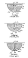
- Figs. 2(a), 2(b) and 2(c) are schematic showings, also from the '534 patent, illustrating tilt camera movement activity therein in common with the subject invention.
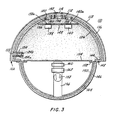
- Fig. 3 is a schematic showing of an outdoor surveillance dome in accordance with the subject invention.
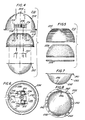
- Fig. 4 is an exploded view of components of an actual rendition of an outdoor surveillance dome of the invention.
- Fig. 5 is an exploded view of components of the spinning assembly of the Fig. 4 dome.
- Fig. 6 is a bottom plan view of the upper half of the dome of Fig. 4 with components assembled therein.
- Fig. 7 is a front elevation of the lower half of the dome of Fig. 4.
- Fig. 8 is a top plan view of the lower half of the dome of Fig. 4.
- Fig. 9 is a functional block diagram of the system of the invention.
- Assembly 1 comprises a shell-like support housing 2 which houses the main components of the assembly.
- Metal plate 5 is secured to the housing by screws 6 and a further plate 7 is situated below plate 5 and is rotatably mounted to the central area 2a by bearing assembly 8.
- Assembly 8 is secured to the housing by bolts 9 and associated nuts and carries a fixed gear 8a at its lower end.
- Threaded members on plate 7 and corresponding nuts serve to fix a drive or pan motor (all shown in the '534 patent) on plate 7 such that the drive gear of the motor engages fixed gear 8a.
- Stabilizer bearings 12 mounted to plate 5 are provided to accomodate momentary imbalances in plate 7 during rotation.
- plate 7 allows the plate to be rotated three-hundred and sixty degrees about a vertical axis.
- the viewing direction 13a of assembly 1 accordingly can pan the entire area under surveillance.
- Assembly 1 is further provided with a viewing means or lens 13 which defines viewing direction 13a.
- Lens 13 views the surveillance area along the direction 13a as assembly 1 pans and provides an image of the viewed surveillance area to a camera assembly which converts the image into a video signal.
- a dome-like cover 15 transmissive to light encloses the foregoing components of assembly 1 and rotates with plate 7.
- Interiorly of dome 15 is a further dome-like member or shroud 20 which also rotates with plate 7.
- Shroud 20 is opaque and provides camouflage for the dome assembly, except for a defined viewing region which is aligned with viewing direction 13a.
- the viewing region is in the form of a slot 20a in the shroud which runs from the apex 20b of the shroud verically circumferentially through an angle of approximately ninety degrees and horizontally circumferentially through an angle of approximately twenty-five degrees, as is seen in Figs. 2(a) - 2(c). This permits the viewing direction 13a to be pivoted or tilted from a horizontal position to a vertical position (directed downwardly) for each pan position of assembly 1.
- the camera assembly comprises a solid state camera in which the solid state image pickup assembly 14a of the camera, i.e., the camera portion which receives the optical image from lens 13, is physically separate from the main body assembly 14b of the camera, i.e., the portion which houses the control electronics for the image pickup as well as the video processing, power and other electronics of camera assembly 14.
- Shutter assembly 62 is mounted to assembly 1 in such a way as to closely follow the lens and pickup assemblies 13 and 14a and to be in close proximity to shroud 20 so as to block the slot portion 20a' below the assemblies.
- Shutter assembly 62 comprises a shutter element 62a which, like the shroud 20 and lens assembly 13, is opaque and which is mounted in alignment with slot 20a by arm 62b.
- outdoor dome 110 in accordance with the present invention includes sunshield 112 of dome shape and defining a central upper threaded opening 114.
- Housing 116 preferably comprised of metal, is situated interiorly of sunshield 112 and has upper openings 118 and 120 therein and side, lower opening 122.
- Intake assembly 124 has one-way valve 124a mounted in registry with opening 122 and filter 124b is in registry with valve 124a.
- Insulating liner 126 is disposed interiorly of housing 116 and has an opening in registry with opening 122 and upper openings 128 and 130 in registry with housing openings 118 and 120.
- a further opening 132 is formed in liner 126 in registry with housing opening 134 and sunshield opening 114. concentric about vertical axis 134 with sunshield opening 114. As is discussed below, such opening 132 is normally closed, being formed by cross-shaped slits in liner 126, to be forced open by movement of cabling therethrough, with the liner then sealing upon the cabling.
- Support plate 136 is securable to housing 116 and has exhaust fans 138 and 140 secured thereto, one-way valves 138a and 140a being disposed in the issuance paths of fans 138 and 140, respectively. Opening 142 in plate 136 is concentric with vertical axis 134.
- Housing 116 further defines inwardly directed flanges 144.
- Light-transmissive lower dome cover 146 is secured to flanges 144 at its flange 148.
- Shroud 150 is opaque and has interior flange 152 for securement to plate 154, which rotates by pan motor structure discussed above in connection with the '534 patent.
- Slot 156 is formed in shroud 150, akin to slot 20a of the '534 patent.
- Camera pickup 158 is disposed in slot 156 and a shutter element (not shown) corresponding to shutter element 62a of the '534 patent likewise resides in slot 156.
- Passage 164 exists between shroud 150 and lower dome cover 146 and is in flow communication with slot 156 and with the interior of the dome assembly.
- sunshield 112 and housing 116 define passage 166 therebetween, which is in flow communication with the ambient environment and all of valves 124a, 138a and 140a.
- Fan 160 and heater 162 are fixedly supported relative to plate 154 in communication with slot 156 and for rotation with plate 154.
- Valves 138a and 140a open when fans 138 and 140 are operative, as above noted, under the influence of the output of the fans. Operation of fans 138 and 140, however, creates negative pressure in the interior of the dome assembly, and valve 124a is negative-pressure-responsive. Accordingly, it opens when fans 138 and 140 operate, and serves as an intake valve, with valves 138a and 140a serving concurrently as outlet valves.
- control system of the invention includes a thermostat 168 which is responsive to the detection of a predetermined low temperature within the dome assembly to provide an output signal on line 170 to controller 172.
- Controller 172 also receives an input signal on line 174 if thermostat 174 detects a predetermined high temperature within the dome assembly.
- Controller 172 is responsive to the line 170 input signal (low dome temperature) to activate its output line 178, energizing heater 160.
- the controller is operative, at all times that the dome assembly is in use, to energize its output line 180, which energizes fan 162 thus on a continuous basis.
- the control system furnishes heated air through slot 156 and circulation passage 164 onto the interior surface of lower dome cover 146 to preclude fogging of the same and otherwise preventing moisture condensation therein and in the interior of the dome.
- valve 124a is closed.
- Valves 138a and 140a are closed since fans 138 and 140 are inoperative. Air flow is indicated in Fig. 9 by the broken lines, solid lines indicating electrical connections.
- the arrangement of the invention is effective to fully isolate the interior of the apparatus from the environment in the heating mode and to place the same in selective communication with the environment during the cooling mode.
- Controller 172 is responsive to the line 174 input signal (high dome temperature) to activate its output line 182, energizing fans 138 and 140. Operation of the fans opens valves 138a and 140a, and creates negative pressure within the dome assembly, opening valve 124a. Ambient air thus flows from the environment through valve 124a, fans 138 and 140, valves 138a and 140a and exhaust passage 166. Since valve 124a occupies only a limited portion of the periphery of passage 166, it will be seen that the air drawn into the dome assembly is largely environmental and quite little is recirculated.
- the invention will be seen to provide a control system for adapting an outdoor surveillance apparatus to environmental conditions, the outdoor surveillance apparatus being of the type having first and second dome-shaped housing assemblies joinable to configure the apparatus in generally spherical form, a camera assembly being supported for movement in the second housing assembly.
- the control system comprises a heater supported with the camera assembly for rotational movement therewith, a circulation fan unit supported with the camera assembly also for movement therewith and for issuing output thereof onto the heater, an exhaust fan unit supported in the first housing assembly, thermostat circuitry for generating first and second output signals indicative of respective first and second temperatures in the dome assembly, and a controller for operating the circulation fan unit continuously during use of the apparatus, operating the heater means upon occurrence of the thermostat circuitry first output signal, and operating the exhaust fan unit upon occurrence of the thermostat circuitry second output signal.
- Dome assembly 200 includes sunshield 202 having central cable and mounting passage 204, adapted by interior threading to receive an exteriorly threaded pipe fixture for supporting the dome, and rain gutter 202a.
- Exhaust fan support plate 206 has a central cable guide 208 projecting upwardly thereof for disposition in passage 204 and includes various hardware, depicted but not otherwise described, for securement to sunshield 202 and for the securement thereto of fans 210 and 212 and valves 214 and 216.
- Housing assembly 218 is also thereby secured to sunshield 202, as is camera and shutter support rotational bracket 220.
- Lower dome assembly 222 is securable also to housing assembly 218.
- Housing assembly 218 is seen in the exploded view of Fig. 5 to include housing 224, liner 226 of insulative material and rubber gasket 228.
- Liner 226 preferably defines intake valve 124a.
- housing 224 defines spaced joinder flanges 230 as seen in Fig. 6.
- Cable 232 energizes fans 210 and 212 and will be understood to correspond to line 182 of the control system of Fig. 9.
- Intake valve assembly 234 likewise corresponds to valve assembly 124 of Fig. 3.
- Liner 226 has cross-cuts at 226a, which facilitate sealed passage of cabling therethrough.
- lower dome assembly 222 has interior opaque shroud 236 and outer cover 238, which is light transmissive, and includes lanyard 240 for suspending the same from the upper dome assembly as is customary for repair and maintenance. Tamper-resistant screws are placed through openings 242 and threaded into flanges 230 of Fig. 6 to secure the lower dome assembly to the upper dome assembly.
- Valves 124a, 138a and 140a preferably are constituted by flappers constrained for flapping movement in only one direction, thereby providing the desired one-way flow activity.
- Liner 226 is preferably constituted as a foamed heat-insulating material and is perimetrically continuous in its dome shape, with its opening in registry with valve assembly 234 closed by the flapper valve thereof except in the course of operation of fans 210 and 212.
- cross-cut area 226a is self-biasingly closed upon the cabling extending therethrough.
- Gasket 228 is sealingly disposed between the upper and lower dome assemblies and lower assembly 222 is without any surface openings. Accordingly, heightened thermal isolation is effected for the dome at large from the ambient environment, other than in the cooling mode wherein communication with the environment is desired.
Applications Claiming Priority (2)
| Application Number | Priority Date | Filing Date | Title |
|---|---|---|---|
| US07/462,007 US4984089A (en) | 1990-01-08 | 1990-01-08 | Outdoor surveillance dome with enhanced environmental aptitude and control system therefor |
| US462007 | 1995-06-05 |
Publications (3)
| Publication Number | Publication Date |
|---|---|
| EP0436797A2 true EP0436797A2 (fr) | 1991-07-17 |
| EP0436797A3 EP0436797A3 (en) | 1992-05-20 |
| EP0436797B1 EP0436797B1 (fr) | 1997-01-15 |
Family
ID=23834847
Family Applications (1)
| Application Number | Title | Priority Date | Filing Date |
|---|---|---|---|
| EP90121439A Expired - Lifetime EP0436797B1 (fr) | 1990-01-08 | 1990-11-09 | Coupole de surveillance d'extérieur ayant une aptitude améliorée à l'environnement |
Country Status (7)
| Country | Link |
|---|---|
| US (1) | US4984089A (fr) |
| EP (1) | EP0436797B1 (fr) |
| JP (1) | JP2628225B2 (fr) |
| AR (1) | AR246831A1 (fr) |
| BR (1) | BR9100030A (fr) |
| CA (1) | CA2025850C (fr) |
| DE (1) | DE69029721T2 (fr) |
Cited By (5)
| Publication number | Priority date | Publication date | Assignee | Title |
|---|---|---|---|---|
| DE4436087A1 (de) * | 1994-10-10 | 1996-04-11 | Siedle & Soehne S | Heizvorrichtung für eine Kamera in einem Gehäuse |
| EP1608152A2 (fr) * | 2004-06-11 | 2005-12-21 | Matsushita Electric Industrial Co., Ltd. | Dispositif de caméra |
| EP1748640A1 (fr) * | 2005-07-27 | 2007-01-31 | Sony Corporation | Caméra |
| US7306383B2 (en) | 2004-07-27 | 2007-12-11 | Robert Bosch Gmbh | Compound dome window for a surveillance camera |
| CN102868850A (zh) * | 2012-08-16 | 2013-01-09 | 浙江宇视科技有限公司 | 一种摄像机加热装置 |
Families Citing this family (38)
| Publication number | Priority date | Publication date | Assignee | Title |
|---|---|---|---|---|
| US5319394A (en) * | 1991-02-11 | 1994-06-07 | Dukek Randy R | System for recording and modifying behavior of passenger in passenger vehicles |
| US5121215A (en) * | 1991-03-01 | 1992-06-09 | Bayport Controls, Inc. | Surveillance camera system |
| US5173585A (en) * | 1991-05-06 | 1992-12-22 | Dokken Brian L | Camera heating jacket |
| US5394208A (en) * | 1993-10-22 | 1995-02-28 | Eastman Kodak Company | Environmental enclosure for a camera |
| US5517236A (en) * | 1994-06-22 | 1996-05-14 | Philips Electronics North America Corporation | Video surveillance system |
| US5627616A (en) * | 1994-06-22 | 1997-05-06 | Philips Electronics North America Corporation | Surveillance camera system |
| US5691765A (en) * | 1995-07-27 | 1997-11-25 | Sensormatic Electronics Corporation | Image forming and processing device and method for use with no moving parts camera |
| US5926210A (en) * | 1995-07-28 | 1999-07-20 | Kalatel, Inc. | Mobile, ground-based platform security system which transmits images that were taken prior to the generation of an input signal |
| US5818519A (en) * | 1996-01-17 | 1998-10-06 | Wren; Clifford T. | Surveillance camera mounting apparatus |
| GB2310293A (en) * | 1996-02-07 | 1997-08-20 | P C Richardson & Co | Camera system |
| US6392704B1 (en) * | 1997-11-07 | 2002-05-21 | Esco Electronics Corporation | Compact video processing system for remote sensing applications |
| US6061087A (en) * | 1998-07-16 | 2000-05-09 | Sensormatic Electronics Corporation | Outdoor enclosure for video surveillance system |
| US6322258B1 (en) * | 1999-07-09 | 2001-11-27 | Philips Electronics North America Corporation | Indoor/outdoor surveillance housing with environmental protection |
| US6643456B1 (en) * | 1999-07-09 | 2003-11-04 | Robert Bosch, Gmbh | Environmental shroud |
| US6678001B1 (en) * | 1999-11-01 | 2004-01-13 | Elbex Video Ltd. | Ball shaped camera housing with simplified positioning |
| JP2001174902A (ja) * | 1999-12-17 | 2001-06-29 | Elbex Video Ltd | ボール形状カメラ・ハウジング・システム |
| US6357936B1 (en) * | 1999-12-27 | 2002-03-19 | Elbex Video Ltd. | Holder for a ball-shaped television camera or a TV camera case |
| US6850025B1 (en) | 2000-06-30 | 2005-02-01 | Sensormatic Electronics Corporation | Integrated enclosure and controller for video surveillance camera |
| US6992723B1 (en) | 2000-06-30 | 2006-01-31 | Sensormatic Electronics Corporation | Integrated enclosure for video surveillance camera |
| US20020140850A1 (en) * | 2001-03-29 | 2002-10-03 | Pelco | Heavy duty pendant with dome guard for dome camera system |
| US20020140848A1 (en) * | 2001-03-30 | 2002-10-03 | Pelco | Controllable sealed chamber for surveillance camera |
| US6715939B2 (en) * | 2001-07-27 | 2004-04-06 | Pelco | Universal surveillance camera holder and adaptor |
| US6652164B2 (en) * | 2002-03-28 | 2003-11-25 | Pelco | Retractable camera mounting mechanism |
| US7699691B1 (en) * | 2005-05-11 | 2010-04-20 | L-3 Communications Sonoma Eo, Inc. | Cooling system and method for enclosed volume |
| US7387453B2 (en) * | 2005-09-02 | 2008-06-17 | Pelco, Inc. | Camera support and mounting assembly |
| ITVI20070213A1 (it) * | 2007-08-02 | 2009-02-03 | Tekno System Spa | Custodia di protezione per telecamere atte alla trasmissione del segnale video in formato digitale. |
| US20090207249A1 (en) * | 2008-02-14 | 2009-08-20 | Bulent Erel | Climate controlled surveillance system |
| US7762731B2 (en) * | 2008-09-12 | 2010-07-27 | Pelco, Inc. | Environmentally sealed enclosure |
| ES2370560T3 (es) * | 2008-11-06 | 2011-12-20 | Axis Ab | Alojamiento para dispositivo electrónico. |
| CA2717524A1 (fr) * | 2009-10-12 | 2011-04-12 | Miracle Recreation Equipment Company | Equipement electrique de terrain de jeu |
| US9332163B2 (en) | 2013-04-10 | 2016-05-03 | Sensormatic Electronics, LLC | Indoor bubble adapter |
| DE112015002735B4 (de) * | 2014-06-11 | 2019-11-21 | Trw Automotive U.S. Llc | Klimatisierung einer Fahrerassistenzkameraumgebung durch einen Kühlventilator |
| KR102200673B1 (ko) | 2014-09-12 | 2021-01-12 | 한화테크윈 주식회사 | 감시 카메라의 히터 구동 장치 |
| EP3141955B1 (fr) * | 2015-09-14 | 2017-11-01 | Axis AB | Procédé d'augmentation de la fiabilité dans les systèmes de surveillance |
| EP3333816B1 (fr) * | 2016-12-09 | 2018-10-03 | Axis AB | Agencement de caméra avec illuminateur |
| EP3447574B1 (fr) | 2017-08-21 | 2019-07-31 | Axis AB | Caméra et procédé de formation de rosée contrôlée à l'intérieur d'une caméra |
| CN112702480B (zh) * | 2019-10-22 | 2023-05-12 | 华为技术有限公司 | 一种摄像机及通信设备 |
| CN112415838B (zh) * | 2020-11-10 | 2022-04-26 | 杭州海康威视数字技术股份有限公司 | 具有加热功能的摄像机视窗罩组件及摄像机 |
Citations (5)
| Publication number | Priority date | Publication date | Assignee | Title |
|---|---|---|---|---|
| DE1020364B (de) | 1955-07-16 | 1957-12-05 | Fernseh Gmbh | Fernsehaufnahmekamera mit Temperaturregelung |
| US3935380A (en) | 1974-12-06 | 1976-01-27 | Coutta John M | Surveillance system |
| US4320949A (en) | 1976-03-03 | 1982-03-23 | Pagano Raymond V | Weatherized housing assembly for camera |
| US4737218A (en) | 1986-12-29 | 1988-04-12 | Armstrong World Industries, Inc. | Method of forming a fabric covered spline assembly |
| US4833534A (en) | 1988-02-19 | 1989-05-23 | Sensormatic Electronics Corporation | Surveillance assembly having enhanced shielding and reduced size |
Family Cites Families (6)
| Publication number | Priority date | Publication date | Assignee | Title |
|---|---|---|---|---|
| US4225881A (en) * | 1978-11-27 | 1980-09-30 | Murray Tovi Designs, Inc. | Discrete surveillance system and method for making a component thereof |
| US4414576A (en) * | 1981-09-25 | 1983-11-08 | Vicon Industries, Inc. | Housing assembly for electrical apparatus |
| DE3144275C1 (de) * | 1981-11-07 | 1983-04-14 | Grundig E.M.V. Elektro-Mechanische Versuchsanstalt Max Grundig & Co KG, 8510 Fürth | "Kompakt-Fernsehkamera für Innenraum- oder Außenverwendung" |
| CA1268654A (fr) * | 1985-10-24 | 1990-05-08 | Arkady Kutman | Support et boitier de camera |
| US4796039A (en) * | 1987-06-22 | 1989-01-03 | Pagano Raymond V | Ballistic rated camera housing and method for forming |
| US4764008A (en) * | 1987-11-19 | 1988-08-16 | Wren Clifford T | Surveillance housing assembly |
-
1990
- 1990-01-08 US US07/462,007 patent/US4984089A/en not_active Expired - Lifetime
- 1990-09-20 CA CA002025850A patent/CA2025850C/fr not_active Expired - Fee Related
- 1990-10-02 JP JP2263237A patent/JP2628225B2/ja not_active Expired - Lifetime
- 1990-10-30 AR AR90318233A patent/AR246831A1/es active
- 1990-11-09 DE DE69029721T patent/DE69029721T2/de not_active Expired - Lifetime
- 1990-11-09 EP EP90121439A patent/EP0436797B1/fr not_active Expired - Lifetime
-
1991
- 1991-01-04 BR BR919100030A patent/BR9100030A/pt not_active IP Right Cessation
Patent Citations (5)
| Publication number | Priority date | Publication date | Assignee | Title |
|---|---|---|---|---|
| DE1020364B (de) | 1955-07-16 | 1957-12-05 | Fernseh Gmbh | Fernsehaufnahmekamera mit Temperaturregelung |
| US3935380A (en) | 1974-12-06 | 1976-01-27 | Coutta John M | Surveillance system |
| US4320949A (en) | 1976-03-03 | 1982-03-23 | Pagano Raymond V | Weatherized housing assembly for camera |
| US4737218A (en) | 1986-12-29 | 1988-04-12 | Armstrong World Industries, Inc. | Method of forming a fabric covered spline assembly |
| US4833534A (en) | 1988-02-19 | 1989-05-23 | Sensormatic Electronics Corporation | Surveillance assembly having enhanced shielding and reduced size |
Cited By (10)
| Publication number | Priority date | Publication date | Assignee | Title |
|---|---|---|---|---|
| DE4436087A1 (de) * | 1994-10-10 | 1996-04-11 | Siedle & Soehne S | Heizvorrichtung für eine Kamera in einem Gehäuse |
| DE4436087C2 (de) * | 1994-10-10 | 2003-06-18 | Siedle & Soehne S | Heizvorrichtung für eine lichtdurchlässige Schutzscheibe eines Schutzgehäuses einer Kamera |
| EP1608152A2 (fr) * | 2004-06-11 | 2005-12-21 | Matsushita Electric Industrial Co., Ltd. | Dispositif de caméra |
| EP1608152A3 (fr) * | 2004-06-11 | 2005-12-28 | Matsushita Electric Industrial Co., Ltd. | Dispositif de caméra |
| US7497632B2 (en) | 2004-06-11 | 2009-03-03 | Panasonic Corporation | Camera device |
| US7306383B2 (en) | 2004-07-27 | 2007-12-11 | Robert Bosch Gmbh | Compound dome window for a surveillance camera |
| EP1748640A1 (fr) * | 2005-07-27 | 2007-01-31 | Sony Corporation | Caméra |
| CN102868850A (zh) * | 2012-08-16 | 2013-01-09 | 浙江宇视科技有限公司 | 一种摄像机加热装置 |
| CN102868850B (zh) * | 2012-08-16 | 2015-10-14 | 浙江宇视科技有限公司 | 一种摄像机加热装置 |
| US9307145B2 (en) | 2012-08-16 | 2016-04-05 | Zhejiang Uniview Technologies Co., Ltd | Video camera with temperature sensor |
Also Published As
| Publication number | Publication date |
|---|---|
| EP0436797B1 (fr) | 1997-01-15 |
| CA2025850C (fr) | 2000-03-07 |
| CA2025850A1 (fr) | 1991-07-09 |
| DE69029721T2 (de) | 1997-08-14 |
| US4984089A (en) | 1991-01-08 |
| BR9100030A (pt) | 1991-10-22 |
| JP2628225B2 (ja) | 1997-07-09 |
| DE69029721D1 (de) | 1997-02-27 |
| EP0436797A3 (en) | 1992-05-20 |
| AR246831A1 (es) | 1994-09-30 |
| JPH03217175A (ja) | 1991-09-24 |
Similar Documents
| Publication | Publication Date | Title |
|---|---|---|
| US4984089A (en) | Outdoor surveillance dome with enhanced environmental aptitude and control system therefor | |
| EP0642053B1 (fr) | Assemblage de surveillance avec air forcé pulsé circonférentiellement contre le dôme observateur | |
| US4320949A (en) | Weatherized housing assembly for camera | |
| JP4309585B2 (ja) | ビデオ監視システム用屋外囲い | |
| US4945367A (en) | Surveillance camera system | |
| CN100521894C (zh) | 循环和外部通风单元 | |
| US20080055409A1 (en) | Surveillance Camera System | |
| JP2902614B2 (ja) | 空気調和機の吐出気流制御装置及びその制御方法 | |
| US10451295B2 (en) | Equipment enclosure with multi-mode temperature control system | |
| US4676073A (en) | Cooling apparatus | |
| CA1258385A (fr) | Dispositif thermostatique programmable pour systeme thermique | |
| JPH05126394A (ja) | 人の分布に追従した空調制御システム | |
| US6325137B1 (en) | Portable liquid cooling and heating apparatus | |
| JPS61195229A (ja) | 空気調和装置 | |
| CA1123646A (fr) | Logement a l'epreuve des intemperies pour camera de surveillance | |
| JPH08159534A (ja) | 局所強化冷房システム | |
| JP2002071195A (ja) | 空気調和機 | |
| JPS5917683Y2 (ja) | 自動車用空調装置の温度検出装置 | |
| KR0182553B1 (ko) | 공기조화기의 토출기류 제어장치 및 그 방법 | |
| KR100187259B1 (ko) | 공기조화기의 토출기류 제어장치 및 그 방법 | |
| JPH0725538Y2 (ja) | 空気調和機 | |
| JPH03154906A (ja) | コンピュータ収納盤の冷却装置 | |
| JPS6354978B2 (fr) | ||
| JPH10205842A (ja) | 室内対流装置 | |
| JPH0553061A (ja) | 反射鏡筒 |
Legal Events
| Date | Code | Title | Description |
|---|---|---|---|
| PUAI | Public reference made under article 153(3) epc to a published international application that has entered the european phase |
Free format text: ORIGINAL CODE: 0009012 |
|
| AK | Designated contracting states |
Kind code of ref document: A2 Designated state(s): DE FR GB SE |
|
| PUAL | Search report despatched |
Free format text: ORIGINAL CODE: 0009013 |
|
| AK | Designated contracting states |
Kind code of ref document: A3 Designated state(s): DE FR GB SE |
|
| 17P | Request for examination filed |
Effective date: 19920703 |
|
| 17Q | First examination report despatched |
Effective date: 19940330 |
|
| GRAG | Despatch of communication of intention to grant |
Free format text: ORIGINAL CODE: EPIDOS AGRA |
|
| GRAH | Despatch of communication of intention to grant a patent |
Free format text: ORIGINAL CODE: EPIDOS IGRA |
|
| GRAH | Despatch of communication of intention to grant a patent |
Free format text: ORIGINAL CODE: EPIDOS IGRA |
|
| GRAA | (expected) grant |
Free format text: ORIGINAL CODE: 0009210 |
|
| AK | Designated contracting states |
Kind code of ref document: B1 Designated state(s): DE FR GB SE |
|
| REF | Corresponds to: |
Ref document number: 69029721 Country of ref document: DE Date of ref document: 19970227 |
|
| ET | Fr: translation filed | ||
| PLBE | No opposition filed within time limit |
Free format text: ORIGINAL CODE: 0009261 |
|
| STAA | Information on the status of an ep patent application or granted ep patent |
Free format text: STATUS: NO OPPOSITION FILED WITHIN TIME LIMIT |
|
| 26N | No opposition filed | ||
| REG | Reference to a national code |
Ref country code: GB Ref legal event code: IF02 |
|
| PGFP | Annual fee paid to national office [announced via postgrant information from national office to epo] |
Ref country code: SE Payment date: 20031121 Year of fee payment: 14 |
|
| REG | Reference to a national code |
Ref country code: FR Ref legal event code: CA |
|
| REG | Reference to a national code |
Ref country code: GB Ref legal event code: 732E |
|
| PG25 | Lapsed in a contracting state [announced via postgrant information from national office to epo] |
Ref country code: SE Free format text: LAPSE BECAUSE OF NON-PAYMENT OF DUE FEES Effective date: 20041110 |
|
| EUG | Se: european patent has lapsed | ||
| PGFP | Annual fee paid to national office [announced via postgrant information from national office to epo] |
Ref country code: DE Payment date: 20091127 Year of fee payment: 20 |
|
| PGFP | Annual fee paid to national office [announced via postgrant information from national office to epo] |
Ref country code: FR Payment date: 20091201 Year of fee payment: 20 Ref country code: GB Payment date: 20091125 Year of fee payment: 20 |
|
| REG | Reference to a national code |
Ref country code: GB Ref legal event code: PE20 Expiry date: 20101108 |
|
| PG25 | Lapsed in a contracting state [announced via postgrant information from national office to epo] |
Ref country code: GB Free format text: LAPSE BECAUSE OF EXPIRATION OF PROTECTION Effective date: 20101108 |
|
| PG25 | Lapsed in a contracting state [announced via postgrant information from national office to epo] |
Ref country code: DE Free format text: LAPSE BECAUSE OF EXPIRATION OF PROTECTION Effective date: 20101109 |