EP3141955B1 - Procédé d'augmentation de la fiabilité dans les systèmes de surveillance - Google Patents
Procédé d'augmentation de la fiabilité dans les systèmes de surveillance Download PDFInfo
- Publication number
- EP3141955B1 EP3141955B1 EP15184986.6A EP15184986A EP3141955B1 EP 3141955 B1 EP3141955 B1 EP 3141955B1 EP 15184986 A EP15184986 A EP 15184986A EP 3141955 B1 EP3141955 B1 EP 3141955B1
- Authority
- EP
- European Patent Office
- Prior art keywords
- motor
- power
- measured
- directing arrangement
- motorised
- Prior art date
- Legal status (The legal status is an assumption and is not a legal conclusion. Google has not performed a legal analysis and makes no representation as to the accuracy of the status listed.)
- Active
Links
- 238000000034 method Methods 0.000 title claims description 23
- 238000012544 monitoring process Methods 0.000 title description 2
- 238000010438 heat treatment Methods 0.000 claims description 49
- 239000003990 capacitor Substances 0.000 claims description 11
- 230000000694 effects Effects 0.000 description 4
- 238000010586 diagram Methods 0.000 description 3
- 230000007257 malfunction Effects 0.000 description 3
- 230000003213 activating effect Effects 0.000 description 2
- 230000000712 assembly Effects 0.000 description 2
- 238000000429 assembly Methods 0.000 description 2
- 230000007423 decrease Effects 0.000 description 2
- 238000013461 design Methods 0.000 description 2
- 238000012545 processing Methods 0.000 description 2
- 239000004065 semiconductor Substances 0.000 description 2
- 230000005355 Hall effect Effects 0.000 description 1
- 238000003491 array Methods 0.000 description 1
- 238000004891 communication Methods 0.000 description 1
- 230000003247 decreasing effect Effects 0.000 description 1
- 238000005516 engineering process Methods 0.000 description 1
- 230000003993 interaction Effects 0.000 description 1
- 238000012986 modification Methods 0.000 description 1
- 230000004048 modification Effects 0.000 description 1
- 230000001151 other effect Effects 0.000 description 1
Images

Classifications
-
- G—PHYSICS
- G05—CONTROLLING; REGULATING
- G05D—SYSTEMS FOR CONTROLLING OR REGULATING NON-ELECTRIC VARIABLES
- G05D23/00—Control of temperature
- G05D23/19—Control of temperature characterised by the use of electric means
- G05D23/30—Automatic controllers with an auxiliary heating device affecting the sensing element, e.g. for anticipating change of temperature
- G05D23/32—Automatic controllers with an auxiliary heating device affecting the sensing element, e.g. for anticipating change of temperature with provision for adjustment of the effect of the auxiliary heating device, e.g. a function of time
-
- G—PHYSICS
- G03—PHOTOGRAPHY; CINEMATOGRAPHY; ANALOGOUS TECHNIQUES USING WAVES OTHER THAN OPTICAL WAVES; ELECTROGRAPHY; HOLOGRAPHY
- G03B—APPARATUS OR ARRANGEMENTS FOR TAKING PHOTOGRAPHS OR FOR PROJECTING OR VIEWING THEM; APPARATUS OR ARRANGEMENTS EMPLOYING ANALOGOUS TECHNIQUES USING WAVES OTHER THAN OPTICAL WAVES; ACCESSORIES THEREFOR
- G03B17/00—Details of cameras or camera bodies; Accessories therefor
- G03B17/55—Details of cameras or camera bodies; Accessories therefor with provision for heating or cooling, e.g. in aircraft
-
- G—PHYSICS
- G01—MEASURING; TESTING
- G01J—MEASUREMENT OF INTENSITY, VELOCITY, SPECTRAL CONTENT, POLARISATION, PHASE OR PULSE CHARACTERISTICS OF INFRARED, VISIBLE OR ULTRAVIOLET LIGHT; COLORIMETRY; RADIATION PYROMETRY
- G01J5/00—Radiation pyrometry, e.g. infrared or optical thermometry
-
- G—PHYSICS
- G01—MEASURING; TESTING
- G01K—MEASURING TEMPERATURE; MEASURING QUANTITY OF HEAT; THERMALLY-SENSITIVE ELEMENTS NOT OTHERWISE PROVIDED FOR
- G01K1/00—Details of thermometers not specially adapted for particular types of thermometer
- G01K1/14—Supports; Fastening devices; Arrangements for mounting thermometers in particular locations
-
- G—PHYSICS
- G01—MEASURING; TESTING
- G01R—MEASURING ELECTRIC VARIABLES; MEASURING MAGNETIC VARIABLES
- G01R19/00—Arrangements for measuring currents or voltages or for indicating presence or sign thereof
- G01R19/165—Indicating that current or voltage is either above or below a predetermined value or within or outside a predetermined range of values
- G01R19/16533—Indicating that current or voltage is either above or below a predetermined value or within or outside a predetermined range of values characterised by the application
- G01R19/16538—Indicating that current or voltage is either above or below a predetermined value or within or outside a predetermined range of values characterised by the application in AC or DC supplies
-
- G—PHYSICS
- G03—PHOTOGRAPHY; CINEMATOGRAPHY; ANALOGOUS TECHNIQUES USING WAVES OTHER THAN OPTICAL WAVES; ELECTROGRAPHY; HOLOGRAPHY
- G03B—APPARATUS OR ARRANGEMENTS FOR TAKING PHOTOGRAPHS OR FOR PROJECTING OR VIEWING THEM; APPARATUS OR ARRANGEMENTS EMPLOYING ANALOGOUS TECHNIQUES USING WAVES OTHER THAN OPTICAL WAVES; ACCESSORIES THEREFOR
- G03B17/00—Details of cameras or camera bodies; Accessories therefor
- G03B17/02—Bodies
-
- G—PHYSICS
- G03—PHOTOGRAPHY; CINEMATOGRAPHY; ANALOGOUS TECHNIQUES USING WAVES OTHER THAN OPTICAL WAVES; ELECTROGRAPHY; HOLOGRAPHY
- G03B—APPARATUS OR ARRANGEMENTS FOR TAKING PHOTOGRAPHS OR FOR PROJECTING OR VIEWING THEM; APPARATUS OR ARRANGEMENTS EMPLOYING ANALOGOUS TECHNIQUES USING WAVES OTHER THAN OPTICAL WAVES; ACCESSORIES THEREFOR
- G03B17/00—Details of cameras or camera bodies; Accessories therefor
- G03B17/56—Accessories
- G03B17/561—Support related camera accessories
-
- G—PHYSICS
- G03—PHOTOGRAPHY; CINEMATOGRAPHY; ANALOGOUS TECHNIQUES USING WAVES OTHER THAN OPTICAL WAVES; ELECTROGRAPHY; HOLOGRAPHY
- G03B—APPARATUS OR ARRANGEMENTS FOR TAKING PHOTOGRAPHS OR FOR PROJECTING OR VIEWING THEM; APPARATUS OR ARRANGEMENTS EMPLOYING ANALOGOUS TECHNIQUES USING WAVES OTHER THAN OPTICAL WAVES; ACCESSORIES THEREFOR
- G03B37/00—Panoramic or wide-screen photography; Photographing extended surfaces, e.g. for surveying; Photographing internal surfaces, e.g. of pipe
- G03B37/02—Panoramic or wide-screen photography; Photographing extended surfaces, e.g. for surveying; Photographing internal surfaces, e.g. of pipe with scanning movement of lens or cameras
-
- H—ELECTRICITY
- H02—GENERATION; CONVERSION OR DISTRIBUTION OF ELECTRIC POWER
- H02P—CONTROL OR REGULATION OF ELECTRIC MOTORS, ELECTRIC GENERATORS OR DYNAMO-ELECTRIC CONVERTERS; CONTROLLING TRANSFORMERS, REACTORS OR CHOKE COILS
- H02P8/00—Arrangements for controlling dynamo-electric motors of the kind having motors rotating step by step
- H02P8/12—Control or stabilisation of current
-
- H—ELECTRICITY
- H04—ELECTRIC COMMUNICATION TECHNIQUE
- H04N—PICTORIAL COMMUNICATION, e.g. TELEVISION
- H04N23/00—Cameras or camera modules comprising electronic image sensors; Control thereof
- H04N23/60—Control of cameras or camera modules
- H04N23/695—Control of camera direction for changing a field of view, e.g. pan, tilt or based on tracking of objects
-
- H—ELECTRICITY
- H05—ELECTRIC TECHNIQUES NOT OTHERWISE PROVIDED FOR
- H05B—ELECTRIC HEATING; ELECTRIC LIGHT SOURCES NOT OTHERWISE PROVIDED FOR; CIRCUIT ARRANGEMENTS FOR ELECTRIC LIGHT SOURCES, IN GENERAL
- H05B1/00—Details of electric heating devices
- H05B1/02—Automatic switching arrangements specially adapted to apparatus ; Control of heating devices
- H05B1/0227—Applications
- H05B1/0288—Applications for non specified applications
-
- F—MECHANICAL ENGINEERING; LIGHTING; HEATING; WEAPONS; BLASTING
- F16—ENGINEERING ELEMENTS AND UNITS; GENERAL MEASURES FOR PRODUCING AND MAINTAINING EFFECTIVE FUNCTIONING OF MACHINES OR INSTALLATIONS; THERMAL INSULATION IN GENERAL
- F16D—COUPLINGS FOR TRANSMITTING ROTATION; CLUTCHES; BRAKES
- F16D61/00—Brakes with means for making the energy absorbed available for use
-
- G—PHYSICS
- G03—PHOTOGRAPHY; CINEMATOGRAPHY; ANALOGOUS TECHNIQUES USING WAVES OTHER THAN OPTICAL WAVES; ELECTROGRAPHY; HOLOGRAPHY
- G03B—APPARATUS OR ARRANGEMENTS FOR TAKING PHOTOGRAPHS OR FOR PROJECTING OR VIEWING THEM; APPARATUS OR ARRANGEMENTS EMPLOYING ANALOGOUS TECHNIQUES USING WAVES OTHER THAN OPTICAL WAVES; ACCESSORIES THEREFOR
- G03B2217/00—Details of cameras or camera bodies; Accessories therefor
- G03B2217/007—Details of energy supply or management
Definitions
- the present invention relates to a method for controlling the temperature in a camera assembly. Moreover the present invention relates to temperature controlled and motorized camera mounting device.
- Motorized camera directing arrangements e.g. mounting brackets having pan functionality, tilt functionality, or both pan and tilt functionality, are used in order to vary the captured image view from cameras.
- This type of motorized camera directing arrangements for turning the image view around one or various axes is sometimes built into a camera assembly and in such cases the camera assembly may be referred to as a pan camera, a tilt camera, or a pan-tilt camera.
- the motorized camera directing arrangements includes one or a plurality of motors, gears, pivot axes, and motor controllers. At low temperatures there is a risk that one of these devices malfunctions due to the low temperature and in order to avoid such problems a heater may be arranged in the motorised mounting devices or the camera assemblies, as described in the Japanese patent application JP2007206479(A ).
- a problem of these types of motorised mounting devices or camera assemblies which are heated in order to experience a decreased risk of malfunction due to low temperatures relates to power consumption.
- a problem related to heaters and motors is that they require a lot of power.
- a CPU is arranged to control the heater so that the power consumption of the heater is low or it is not active at all while the motors are running.
- the cost of the power electronics may be kept low as power electronics get more expensive the more power they are to handle.
- One object of the present invention is to provide an improved motorised camera directing arrangement. Another object is to achieve a cost effective motorised camera directing arrangement.
- a method for controlling a heating device in a motorised camera directing arrangement including a motor device, said method comprises measuring a voltage over the motor device, measuring a current conducted at least to the motor device, measuring a temperature relating to the motorised camera directing arrangement, controlling power distributed to the heating device based on the measured temperature and on the measured current, and feeding power to the heating device independent of the measured temperature and the measured current in the event that the measuring of the voltage over the motor device indicates a voltage level higher than a predetermined threshold value.
- the heater controller in addition to heating the motorised camera directing arrangement when cold, engage the heater device when the voltage level over the motor is higher than a predetermined threshold is that the motorised camera directing arrangement may be produced using less components due to the heater being used as a break resistor burning up power surplus generated by a motor that is electrically braking.
- An additional advantage of activating the heater for burning the brake energy by measuring the voltage over the motor is that the heater controller and the motor controller may be kept simple in that the heater controller may operate independent of the motor controller operations, i.e. no communication is necessary as the heater controller is arranged to act upon an effect in the electrical system of the motorised camera directing arrangement that is generated when the motor is braking.
- the camera assembly may be produced cost effectively and it may require less interaction between various controllers simplifying the design.
- the measuring of the current may be arranged so that the combined current to the motor and the heating device is measured. In this way, it is easy to acquire an indication of the total power used by the combined heating and driving operations of the motorised camera directing, which then may be used to determine the power to be used for increase in heating power.
- the controlling of the power distributed to the heating device also is based on the measured voltage.
- the advantage of measuring the voltage as well is that the power consumption may be determined more precisely, especially in a system where the voltage varies.
- the measured voltage may also be used to identify fluctuations in the voltage, e.g., superimposed waveforms on top of an AC-level, this information may be used in order to have the heater use the power feed more efficiently by drawing power when the voltage peaks and avoid drawing power when it dips.
- Such an arrangement may further result in that capacitors of less cost may be used in the system in comparison with a system not considering the voltage fluctuation.
- controlling of the power distributed to the heating device further may comprise dynamically setting a power limit for the heating device based on measured current and dynamically controlling the power distribution to the heating device so that the power limit is not exceeded.
- the motorised camera directing arrangement may be heated by means of the heating device as long as the motor does not use all the power assigned for the motorised camera directing arrangement.
- the feeding of power to the heating device in the event that the measuring of the voltage over the motor device indicates a voltage level higher than a predetermined threshold value, may alternatively include comparing the measured voltage over the motor to a plurality of predetermined threshold values representing discretely increasing voltages and feeding a different amount of power to the heating device depending on the threshold exceeded by the measured voltage.
- the heater may also be activated at various levels of power consumption by the motor.
- the voltage over the motor device is measured over a capacitor arranged in parallel with the motor device.
- the motor may be a first motor of the motorised camera directing arrangement and the motorised camera directing arrangement may include a second motor.
- the current measured may be the current distributed to the motors of the motorised camera directing arrangement and the heating device.
- a motorised camera directing arrangement includes a motor, a power supply, a current sensor, a voltage sensor, a temperature sensor, a heater controller, a motor controller, and a heater, and wherein the motorised camera directing arrangement is configured to perform the method for controlling the heating device in the motorised camera directing arrangement.
- the method comprises measuring a voltage over the motor, measuring a current conducted to the motor, measuring a temperature relating to motorised camera directing device, controlling power distributed to the heating device based on the measured temperature and on the measured current, and feeding power to the heating device independent of the measured temperature and the measured current in the event that the measuring of the voltage over the motor indicates a voltage level higher than a predetermined threshold value.
- the motorised camera directing arrangement may further include a mounting bracket for attaching a camera to the motorised camera directing arrangement.
- a camera may comprise a motorised camera directing arrangement as described above.
- Fig. 1 shows a motorised camera directing device combined with a camera, which may be described as a camera including a motorised camera directing device.
- the motorised camera directing arrangement may include a mounting bracket for a camera instead of the camera itself being incorporated with the motorised camera directing arrangement, i.e. the motorised camera directing device may be seen as a camera accessory arranged to add functionality to the image capturing operation to be performed by a camera mounted thereto.
- the motorised camera directing arrangement may be a camera including motors and pivot shafts for enabling controlled movement of the camera view or it may be a device having a mounting bracket for supporting a camera and which have motors for controlled movement of the mounting bracket and, when mounted, a camera.
- Fig. 1 shows the motorised camera directing arrangement 10 which is arranged for pan and tilt movement of the image view of a camera 16.
- the motorised camera directing arrangement 10 includes a base 12, an intermediate device 14, and the camera 16.
- the intermediate device 14 is turnably connected to the base 12 by means of a pivot shaft 18 and the camera 16 is turnably connected to the intermediate device 14 by means of pivot axes 20a-b.
- the pivot shaft 18 connecting the intermediate device 14 to the base 12 is arranged to enable the intermediate device 14 to turn in a first direction around a first axis 22 and the pivot shafts 20a-b connecting the camera 16 to the intermediate device 14 are arranged to enable the camera to turn in a second direction around a second axis 24.
- the pivot shafts 18 and 20a-b are arranged so that the second axis 24 is orthogonal to the first axis 22.
- the turning of the intermediate device 14 around the first axis 22 is performed by means of a first motor device 25 being arranged in the intermediate device to interact with the pivot shaft 18, the base 12, and the intermediate device in any manner known to the skilled person.
- the turning of the camera 16 around the second axis 24 is performed by means of a second motor device 27.
- the motor devices 25 and 27 may each include a motor 26, 28, and a motor driver 62, 64.
- the motor devices 25 and 27 are controlled by motor controllers 30 and 31.
- the motor controllers 30, 31, may be implemented by means of program code executed in a processing unit 37.
- the motors 26 and 28 are Brushless DC motors (BLDC motors).
- BLDC motors Brushless DC motors
- the design and implementation of the motor device 25, 27 and motor controller 30, 31 may be as described in the publication " Brushless DC Motor Control Made Easy", DS00857A, from Microchip Technology Incorporated, published 2002, and authored by Ward Brown .
- Other examples are given in " Six Step Trapezoidal Control of a BLDC Motor Using Back-EMF", REU05B0073-0101/Rev.1.01, published in February 2009 by Renesas Electronics Corporation , in “ 3-Phase BLDC Motor Control with Hall Sensors Using 56800/E Digital Signal Controllers", AN1916 Rev. 2.0, 11/2005, authored by Leonard N.
- the motor device is an ordinary DC-motor or a stepper motor controlled by a motor controller in any manner known to the skilled person.
- the motorised camera directing arrangement 10 further includes a heater 32, a heater controller 34, and a temperature sensor 36.
- the heater 32 may be any type of resistive heating arrangement, e.g., a wire being warmed by current flowing through it, a current conducting trace on a rigid or a flexible printed circuit board, etc.
- the heater controller 34 may be implemented as program code running in the processing device 37.
- the heater controller 34 is arranged to control the temperature of the motorised camera directing arrangement 10, especially to make sure the motorised camera directing arrangement 10 is not too cold, using inputs from the temperature sensor 36 and controlling the energy sent to or requested by the heater 32.
- the operation of some embodiments of the heater controller will be described below.
- the heater controller functionality may alternatively be implemented using logic circuits, field programmable arrays, ASICs, etc.
- a power supply 38 is included in the motorised camera directing arrangement 10.
- the power supply is arranged in the base 12 and receives external power via a feeding line 40.
- the power supply may be a connection device arranged to distribute the physical power lines for the motors 26, 28 and the heater 32.
- the power supply may include power supply module including a transformer, a rectifier, and/or other electrical devices for adapting the power from the feeding line to the required power of the system.
- the motorised camera directing arrangement 10 also includes power circuitry 39.
- the power circuitry 39 may include some measuring sensors, e.g., a sensor measuring voltage and a sensor measuring current, discussed in more detail below, and a capacitor acting as a current buffer, also discussed in more detail below.
- Fig. 2 in which a schematic electric circuit diagram of possible embodiments is showed.
- the motor devices 25 and 27 are controlled by means of the motor controllers 30 and 31 sending control signals to separate control devices 62, 64 one for each motor device 25, 27 and thereby each motor 26, 28.
- Each control device 62, 64 controls characteristics of the power feed to the motor 26, 28 from the power supply 38 in order to control the rotation of the motor 26, 28.
- the control devices In the case of the motors being BLDC motors the control devices generate three phase driving power to the motors based on signals received from the motor controllers 30, 31.
- the motor controllers 30, 31, may be arranged to control the motors 26, 28 without input from the heater controller 34 or output to the heater controller 34. Thereby, the motor controllers 30, 31, may be kept at a low cost and at relatively low complexity, which also decreases the risk of malfunction of the motorised camera directing arrangement 10.
- the heater controller 34 is arranged to receive a signal indicating the total current distributed to the heater 32, and the motors 26, 28. This signal is provided by means of a current sensor 66 arranged on a line conducting current to the heater 32, and the motors 26, 28. Further, the heater controller 34 is arranged to receive a signal indicating the voltage level over the motor devices 25, 27. In the figure this is achieved by arranging a voltage sensor 68 measuring the voltage over a capacitor 70, which is connected in parallel with the motor devices 25, 27. An output signal is generated by the heater controller based on the measured current, the measured voltage, and the measured temperature, the temperature sensor 36 is showed in Fig. 1 . This output signal is connected to a control device 72 controlling the characteristics of the power provided to the heater 32 in order to vary the heating power generated or simply turn it off.
- the capacitor 70 may have two effects in the circuit. One of them is that it acts as a low pass filter for high frequency ripples originating from the motor devices 25 and 27 which are controlled about 20 000 times per second. These high frequency disturbances are thereby filtered before they effect the power feeding system. The other effect is that the capacitor 70 is charged with braking effect from the motor devices 25, 27, when a motor is braking. This energy captured by the capacitor results in an increase in voltage over the capacitor which may be measured by the voltage meter 68.
- the heater controller 34 is arranged to act upon such voltage increase by activating the heater 32 and thereby "burning" the excess energy and making the heater act as a braking resistor.
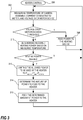
- a method 200 performed by the heater controller 34 includes measuring of the temperature in the motorised camera directing arrangement 10, the current conducted to the motor and the voltage over the motor device, step 202. If the measured voltage exceeds a predetermined threshold value then the heater controller 34 will determine the power to be fed to the heating device in order to burn up excess energy, step 208.
- the predetermined voltage threshold may be set to a value slightly higher than the feeding power delivered for the motors. In some embodiments the normal operational voltage may be 48V with a superposed voltage wave, i.e. voltage fluctuation, of less than 3V. In such an embodiment the predetermined voltage threshold may be set to 51V. The skilled person realizes that other voltages are equally suitable for the present implementation.
- the system is not necessarily limited to a 48V system, but may be a system implementing any voltage, e.g., it may be a system implementing anything from 3V to 230V.
- the superimposed voltage wave may be 5% of the system voltage, however, this may also vary depending on how well the power supply is performing.
- the higher voltage value arranged to trigger the heater controller to start the heating may be a result of a motor device 25, 27, applying electrical brakes which generate power instead of consuming power, and thereby charging the capacitor 70 in the circuit, resulting in a higher voltage measured over the motor device 25, 27, and the capacitor 70, as they are connected in parallel.
- the method returns to step 202 in order to continue monitoring the motorised camera directing arrangement 10.
- a required heating power is determined based on the measured temperature, step 210.
- the control of the heating power may be simple, e.g. if the temperature falls below a certain temperature threshold, heating power is required and if not, no heating power is required. In other embodiments the heating power may be proportional to the decrease in temperature when the temperature is below a threshold temperature or the heating power may be determined from a plurality of threshold temperatures, each threshold resulting in a different amount of heating power, e.g., more heating power at lower temperature. If no heating power is needed, then the heater controller 34 returns to step 202 for measuring. However, if heating power is required, the heater controller 34 is also designed to limit the total amount of power used by the motorised camera directing arrangement 10.
- this is achieved by calculating a maximum power limit, P HEATMAX , for the heater based on the measured current, which is indicating the power used by the motors P MOTORS , and a power limit for the system, P LIMIT , step 212.
- This power limit is then applied when determining the amount of power to feed to the heater 32, e.g., by allowing the heater 32 to use power up to the value of P HEATMAX . Accordingly, if the required heating power determined in step 210 is below or equal to P HEATMAX the heater 32 is allowed to use the required heating power.
- the heater controller 34 sends signals to the heater control device 72 to feed the determined amount to the heater 32, step 216. Then the process returns and measures the temperature, current, and voltage again, step 202.
- the limiting of the heating power based on power used by the motors is simply designed not to allow any heating at the same time as the motors are in use, e.g., as long as any one of the motors is drawing power.
- the power feed may present a voltage that is 48V having a 5% 100Hz sinus wave shaped voltage signal superimposed.
- the voltage levels and the frequency may of course have other values, as presented above.
- any of the controllers, or all of them may be arranged to make a load, e.g., the heater 32, draw current at the peak, or during a time period including the peak, of the superimposed voltage in order to have the system draw as little current as possible.
Claims (12)
- Procédé de commande d'un dispositif de chauffage (32) dans un dispositif de direction de caméra motorisé (10) incluant un dispositif à moteur (25, 27), ledit procédé comprenant de :mesurer une température relative au dispositif de direction de caméra motorisé (10), caractérisé par :mesurer une tension sur le dispositif à moteur (25, 27),mesurer un courant conduit au moins vers le dispositif à moteur (25, 27),commander une alimentation électrique distribuée au dispositif de chauffage (32) sur la base de la température mesurée et du courant mesuré, etalimenter une alimentation électrique dans le dispositif de chauffage (32) indépendamment de la température mesurée et du courant mesuré au cas où la mesure de la tension sur le dispositif à moteur indique un niveau de tension supérieur à une valeur seuil prédéterminée, amenant le dispositif de chauffage (32) à agir comme une résistance de freinage.
- Procédé selon la revendication 1, dans lequel la mesure du courant est agencée de sorte que le courant combiné du dispositif à moteur (25, 27) et du dispositif de chauffage (32) soit mesuré.
- Procédé selon la revendication 1, dans lequel commander l'alimentation électrique distribuée au dispositif de chauffage(32) est aussi basé sur la tension mesurée.
- Procédé selon une quelconque des revendications 1 à 3, dans lequel la commande de l'alimentation électrique distribuée au dispositif de chauffage (32) comprend en outre de régler dynamiquement une limite de puissance pour le dispositif de chauffage (32) sur la base du courant mesuré et de commander dynamiquement la distribution d'alimentation électrique au dispositif de chauffage (32) de sorte que la limite d'alimentation électrique ne soit pas dépassée.
- Procédé selon une quelconque des revendications 1 à 4, dans lequel l'alimentation électrique du dispositif de chauffage (32), au cas où la mesure de la tension sur le dispositif de moteur (25, 27) inclut un niveau de tension supérieure à une valeur seuil prédéterminée, inclut en outre de comparer la tension mesurée sur le dispositif à moteur (25, 27) avec une pluralité de valeurs seuils prédéterminées représentant l'augmentation discrète de tensions et l'alimentation d'une quantité différente d'alimentation électrique dans le dispositif de chauffage (32) en fonction du seuil dépassé par la tension mesurée.
- Procédé selon une quelconque des revendications 1 - 5, dans lequel la tension sur le dispositif à moteur (25, 27) est mesurée sur un condensateur (70) disposé en parallèle au dispositif à moteur (25, 27).
- Procédé selon une quelconque des revendications 1 - 6, dans lequel le dispositif à moteur (25, 27) est un premier dispositif à moteur (25) de l'agencement de direction de caméra motorisé (10) et l'agencement de direction de caméra motorisé (10) inclut un second dispositif à moteur (27).
- Procédé selon une quelconque des revendications 1 - 7, dans lequel le courant mesuré est le courant distribué au moins aux dispositifs à moteur (25, 27) et au dispositif de chauffage (32) de l'agencement de direction de caméra motorisé (10).
- Agencement de direction de caméra motorisé (10) incluant un dispositif à moteur (25, 27), une alimentation électrique (38), un capteur de courant (66), un capteur de tension (68), un capteur de température (36), un contrôleur de chauffage (34), un contrôleur de moteur (30, 31) et un chauffage (32), dans lequel le contrôleur de chauffage (34) de l'agencement de direction de caméra motorisé (10) est configuré pour exécuter les actes d'une quelconque des revendications 1 - 8.
- Agencement de direction de caméra motorisé (10) selon la revendication 9, dans lequel le dispositif de moteur (25, 27) inclut un entraînement de moteur (62, 64) et un moteur (26, 28).
- Agencement de direction de caméra motorisé (10) selon une quelconque des revendications 9 - 10, incluant en outre une console de montage pour fixer une caméra à l'agencement de direction de caméra motorisé (10).
- Caméra comprenant un agencement de direction de caméra motorisé (10) selon une quelconque des revendications 9 - 11.
Priority Applications (6)
| Application Number | Priority Date | Filing Date | Title |
|---|---|---|---|
| EP15184986.6A EP3141955B1 (fr) | 2015-09-14 | 2015-09-14 | Procédé d'augmentation de la fiabilité dans les systèmes de surveillance |
| JP2016164704A JP6325614B2 (ja) | 2015-09-14 | 2016-08-25 | モニタリングシステムにおける信頼性を高めるための方法 |
| TW105128388A TWI639073B (zh) | 2015-09-14 | 2016-09-02 | 增加監控系統內之可靠性之方法 |
| KR1020160113341A KR101915629B1 (ko) | 2015-09-14 | 2016-09-02 | 모니터링 시스템들에서 신뢰성을 증가시키기 위한 방법 |
| CN201610802319.5A CN106527540B (zh) | 2015-09-14 | 2016-09-05 | 提高监控系统的可靠性的方法 |
| US15/265,327 US9872340B2 (en) | 2015-09-14 | 2016-09-14 | Method for increasing reliability in monitoring systems |
Applications Claiming Priority (1)
| Application Number | Priority Date | Filing Date | Title |
|---|---|---|---|
| EP15184986.6A EP3141955B1 (fr) | 2015-09-14 | 2015-09-14 | Procédé d'augmentation de la fiabilité dans les systèmes de surveillance |
Publications (2)
| Publication Number | Publication Date |
|---|---|
| EP3141955A1 EP3141955A1 (fr) | 2017-03-15 |
| EP3141955B1 true EP3141955B1 (fr) | 2017-11-01 |
Family
ID=54151091
Family Applications (1)
| Application Number | Title | Priority Date | Filing Date |
|---|---|---|---|
| EP15184986.6A Active EP3141955B1 (fr) | 2015-09-14 | 2015-09-14 | Procédé d'augmentation de la fiabilité dans les systèmes de surveillance |
Country Status (6)
| Country | Link |
|---|---|
| US (1) | US9872340B2 (fr) |
| EP (1) | EP3141955B1 (fr) |
| JP (1) | JP6325614B2 (fr) |
| KR (1) | KR101915629B1 (fr) |
| CN (1) | CN106527540B (fr) |
| TW (1) | TWI639073B (fr) |
Families Citing this family (4)
| Publication number | Priority date | Publication date | Assignee | Title |
|---|---|---|---|---|
| EP3141955B1 (fr) * | 2015-09-14 | 2017-11-01 | Axis AB | Procédé d'augmentation de la fiabilité dans les systèmes de surveillance |
| CN110832197B (zh) * | 2017-06-30 | 2021-06-25 | 维斯塔斯风力系统集团公司 | 用于风轮机叶片的改进的电热加热系统 |
| CN113014802B (zh) * | 2021-02-02 | 2022-08-16 | 浙江大华技术股份有限公司 | 云台摄像机的控制方法、装置和计算机设备 |
| US20230067632A1 (en) * | 2021-08-31 | 2023-03-02 | Texas Instruments Incorporated | Current regulation for stepper motors using dual loop control through voltage mode and current mode |
Family Cites Families (23)
| Publication number | Priority date | Publication date | Assignee | Title |
|---|---|---|---|---|
| US4320949A (en) * | 1976-03-03 | 1982-03-23 | Pagano Raymond V | Weatherized housing assembly for camera |
| US4984089A (en) * | 1990-01-08 | 1991-01-08 | Sensormatic Electronics Corporation | Outdoor surveillance dome with enhanced environmental aptitude and control system therefor |
| JPH0733493Y2 (ja) * | 1992-02-12 | 1995-07-31 | リズム時計工業株式会社 | 監視カメラ装置 |
| US5394184A (en) * | 1993-08-30 | 1995-02-28 | Sensormatic Electronics Corporation | Surveillance assembly having circumferential delivery of forced air to viewing bubble |
| JP4281398B2 (ja) * | 2003-04-09 | 2009-06-17 | パナソニック株式会社 | 画像形成装置及び印字制御方法 |
| KR101133122B1 (ko) * | 2005-02-24 | 2012-04-06 | 삼성테크윈 주식회사 | 온도에 적응적으로 작동하는 감시 카메라 |
| US20070036540A1 (en) * | 2005-08-11 | 2007-02-15 | Nama Dino R | Positioner with slip clutch |
| CA2523744A1 (fr) * | 2005-10-19 | 2007-04-19 | Somboun Chia | Camera de dome |
| US20070144800A1 (en) * | 2005-11-30 | 2007-06-28 | Stone Kevin T | System and method for braking resistor supplemental heating |
| US20070126872A1 (en) * | 2005-12-06 | 2007-06-07 | Michael Bolotine | Modular surveillance camera system |
| JP2007206479A (ja) | 2006-02-03 | 2007-08-16 | Hitachi Kokusai Electric Inc | カメラ装置 |
| JP5067864B2 (ja) * | 2007-12-12 | 2012-11-07 | キヤノン株式会社 | 電源制御回路、撮像装置及び制御方法 |
| JP2009225146A (ja) * | 2008-03-17 | 2009-10-01 | Nec Corp | 旋回カメラ装置、該旋回カメラ装置に用いられる温度制御方法及び温度制御プログラム |
| JP2010130061A (ja) * | 2008-11-25 | 2010-06-10 | Hitachi Kokusai Electric Inc | 電動雲台カメラ装置 |
| JP5572542B2 (ja) * | 2010-12-27 | 2014-08-13 | 東芝テリー株式会社 | 旋回カメラ装置 |
| FR2976422B1 (fr) * | 2011-06-08 | 2014-10-31 | Valeo Equip Electr Moteur | Procede de controle d'un couple resistant d'un alternateur de vehicule automobile, et systeme de mise en oeuvre de ce procede |
| US9568807B2 (en) * | 2011-11-02 | 2017-02-14 | Wild Goose Imaging Inc. | Method and apparatus for cleaning transparent enclosure for submersible camera |
| US9329457B2 (en) * | 2012-08-22 | 2016-05-03 | Sensormatic Electronics, LLC | Method and system for detecting and clearing camera bubble misting |
| EP2965152B1 (fr) * | 2013-03-04 | 2020-01-22 | Earthcam Inc. | Système de caméra pour tous les temps et procédés pour sa commande |
| US9092030B2 (en) * | 2013-03-14 | 2015-07-28 | Rockwell Automation Technologies, Inc. | Method to implement drive diagnostics and prognostics automatically |
| US9348197B2 (en) * | 2013-12-24 | 2016-05-24 | Pv Labs Inc. | Platform stabilization system |
| JP6205277B2 (ja) * | 2014-01-24 | 2017-09-27 | 株式会社日立国際電気 | テレビジョンカメラシステム |
| EP3141955B1 (fr) * | 2015-09-14 | 2017-11-01 | Axis AB | Procédé d'augmentation de la fiabilité dans les systèmes de surveillance |
-
2015
- 2015-09-14 EP EP15184986.6A patent/EP3141955B1/fr active Active
-
2016
- 2016-08-25 JP JP2016164704A patent/JP6325614B2/ja active Active
- 2016-09-02 KR KR1020160113341A patent/KR101915629B1/ko active IP Right Grant
- 2016-09-02 TW TW105128388A patent/TWI639073B/zh active
- 2016-09-05 CN CN201610802319.5A patent/CN106527540B/zh active Active
- 2016-09-14 US US15/265,327 patent/US9872340B2/en active Active
Non-Patent Citations (1)
| Title |
|---|
| None * |
Also Published As
| Publication number | Publication date |
|---|---|
| CN106527540B (zh) | 2019-04-19 |
| CN106527540A (zh) | 2017-03-22 |
| KR20170032180A (ko) | 2017-03-22 |
| US20170079088A1 (en) | 2017-03-16 |
| JP2017116914A (ja) | 2017-06-29 |
| US9872340B2 (en) | 2018-01-16 |
| TW201725464A (zh) | 2017-07-16 |
| EP3141955A1 (fr) | 2017-03-15 |
| JP6325614B2 (ja) | 2018-05-16 |
| TWI639073B (zh) | 2018-10-21 |
| KR101915629B1 (ko) | 2018-11-06 |
Similar Documents
| Publication | Publication Date | Title |
|---|---|---|
| US9872340B2 (en) | Method for increasing reliability in monitoring systems | |
| JP5958572B2 (ja) | 回転角検出装置、および、これを用いた電動パワーステアリング装置 | |
| US10014716B2 (en) | Discrete energy reservoir with diagnostics | |
| US7005818B2 (en) | Motor actuator with torque control | |
| US20200321769A1 (en) | Control device | |
| US20190193774A1 (en) | Power steering apparatus | |
| JP2023052324A (ja) | 車両のフラップを調節するための制御モジュール | |
| AU2004311723A1 (en) | Identification of electric heater capacity | |
| GB2453878A (en) | Regenerative braking device | |
| CN107107948A (zh) | 用于机动车的自动驾驶的转向系统 | |
| KR20130084592A (ko) | 팬 제어 방법 | |
| JP4524663B2 (ja) | 車両用電圧制御装置 | |
| JP2017103864A (ja) | インバータ装置 | |
| CN105940602A (zh) | 具有位置传感器的致动器 | |
| CN110855197A (zh) | 用于电整流的电动机的自适应的保持通电 | |
| CN107924167B (zh) | 百叶窗控制系统 | |
| WO2011011095A1 (fr) | Système et procédé de surveillance de signal de phase de générateur et de commande de distribution de courant électrique | |
| CN104579109B (zh) | 一种电子换相电机的控制方法 | |
| JP2014007805A (ja) | 直流モータの速度制御装置 | |
| EP3625864B1 (fr) | Procédé de fonctionnement d'un système d'entraînement et système d'entraînement pour la mise en oeuvre d'un tel procédé | |
| US9369028B2 (en) | Electronically commutated motor | |
| JP7079104B2 (ja) | 電池セル温度調整装置 | |
| JP6361016B2 (ja) | 送風機器 | |
| US11729508B2 (en) | Control circuit, PTZ camera, control method, and computer-readable storage medium | |
| CN111987974B (zh) | 旋转电机控制装置 |
Legal Events
| Date | Code | Title | Description |
|---|---|---|---|
| PUAI | Public reference made under article 153(3) epc to a published international application that has entered the european phase |
Free format text: ORIGINAL CODE: 0009012 |
|
| STAA | Information on the status of an ep patent application or granted ep patent |
Free format text: STATUS: REQUEST FOR EXAMINATION WAS MADE |
|
| 17P | Request for examination filed |
Effective date: 20160721 |
|
| AK | Designated contracting states |
Kind code of ref document: A1 Designated state(s): AL AT BE BG CH CY CZ DE DK EE ES FI FR GB GR HR HU IE IS IT LI LT LU LV MC MK MT NL NO PL PT RO RS SE SI SK SM TR |
|
| AX | Request for extension of the european patent |
Extension state: BA ME |
|
| GRAP | Despatch of communication of intention to grant a patent |
Free format text: ORIGINAL CODE: EPIDOSNIGR1 |
|
| STAA | Information on the status of an ep patent application or granted ep patent |
Free format text: STATUS: GRANT OF PATENT IS INTENDED |
|
| RIC1 | Information provided on ipc code assigned before grant |
Ipc: G03B 37/02 20060101AFI20170614BHEP Ipc: F16D 61/00 20060101ALN20170614BHEP Ipc: G03B 17/55 20060101ALI20170614BHEP |
|
| INTG | Intention to grant announced |
Effective date: 20170714 |
|
| GRAS | Grant fee paid |
Free format text: ORIGINAL CODE: EPIDOSNIGR3 |
|
| GRAA | (expected) grant |
Free format text: ORIGINAL CODE: 0009210 |
|
| STAA | Information on the status of an ep patent application or granted ep patent |
Free format text: STATUS: THE PATENT HAS BEEN GRANTED |
|
| AK | Designated contracting states |
Kind code of ref document: B1 Designated state(s): AL AT BE BG CH CY CZ DE DK EE ES FI FR GB GR HR HU IE IS IT LI LT LU LV MC MK MT NL NO PL PT RO RS SE SI SK SM TR |
|
| REG | Reference to a national code |
Ref country code: GB Ref legal event code: FG4D |
|
| REG | Reference to a national code |
Ref country code: SE Ref legal event code: TRGR |
|
| REG | Reference to a national code |
Ref country code: CH Ref legal event code: EP Ref country code: AT Ref legal event code: REF Ref document number: 942620 Country of ref document: AT Kind code of ref document: T Effective date: 20171115 |
|
| REG | Reference to a national code |
Ref country code: IE Ref legal event code: FG4D |
|
| REG | Reference to a national code |
Ref country code: DE Ref legal event code: R096 Ref document number: 602015005703 Country of ref document: DE |
|
| REG | Reference to a national code |
Ref country code: NL Ref legal event code: MP Effective date: 20171101 |
|
| REG | Reference to a national code |
Ref country code: LT Ref legal event code: MG4D |
|
| REG | Reference to a national code |
Ref country code: AT Ref legal event code: MK05 Ref document number: 942620 Country of ref document: AT Kind code of ref document: T Effective date: 20171101 |
|
| PG25 | Lapsed in a contracting state [announced via postgrant information from national office to epo] |
Ref country code: ES Free format text: LAPSE BECAUSE OF FAILURE TO SUBMIT A TRANSLATION OF THE DESCRIPTION OR TO PAY THE FEE WITHIN THE PRESCRIBED TIME-LIMIT Effective date: 20171101 Ref country code: LT Free format text: LAPSE BECAUSE OF FAILURE TO SUBMIT A TRANSLATION OF THE DESCRIPTION OR TO PAY THE FEE WITHIN THE PRESCRIBED TIME-LIMIT Effective date: 20171101 Ref country code: NL Free format text: LAPSE BECAUSE OF FAILURE TO SUBMIT A TRANSLATION OF THE DESCRIPTION OR TO PAY THE FEE WITHIN THE PRESCRIBED TIME-LIMIT Effective date: 20171101 Ref country code: FI Free format text: LAPSE BECAUSE OF FAILURE TO SUBMIT A TRANSLATION OF THE DESCRIPTION OR TO PAY THE FEE WITHIN THE PRESCRIBED TIME-LIMIT Effective date: 20171101 Ref country code: NO Free format text: LAPSE BECAUSE OF FAILURE TO SUBMIT A TRANSLATION OF THE DESCRIPTION OR TO PAY THE FEE WITHIN THE PRESCRIBED TIME-LIMIT Effective date: 20180201 |
|
| PG25 | Lapsed in a contracting state [announced via postgrant information from national office to epo] |
Ref country code: HR Free format text: LAPSE BECAUSE OF FAILURE TO SUBMIT A TRANSLATION OF THE DESCRIPTION OR TO PAY THE FEE WITHIN THE PRESCRIBED TIME-LIMIT Effective date: 20171101 Ref country code: GR Free format text: LAPSE BECAUSE OF FAILURE TO SUBMIT A TRANSLATION OF THE DESCRIPTION OR TO PAY THE FEE WITHIN THE PRESCRIBED TIME-LIMIT Effective date: 20180202 Ref country code: AT Free format text: LAPSE BECAUSE OF FAILURE TO SUBMIT A TRANSLATION OF THE DESCRIPTION OR TO PAY THE FEE WITHIN THE PRESCRIBED TIME-LIMIT Effective date: 20171101 Ref country code: RS Free format text: LAPSE BECAUSE OF FAILURE TO SUBMIT A TRANSLATION OF THE DESCRIPTION OR TO PAY THE FEE WITHIN THE PRESCRIBED TIME-LIMIT Effective date: 20171101 Ref country code: BG Free format text: LAPSE BECAUSE OF FAILURE TO SUBMIT A TRANSLATION OF THE DESCRIPTION OR TO PAY THE FEE WITHIN THE PRESCRIBED TIME-LIMIT Effective date: 20180201 Ref country code: LV Free format text: LAPSE BECAUSE OF FAILURE TO SUBMIT A TRANSLATION OF THE DESCRIPTION OR TO PAY THE FEE WITHIN THE PRESCRIBED TIME-LIMIT Effective date: 20171101 Ref country code: IS Free format text: LAPSE BECAUSE OF FAILURE TO SUBMIT A TRANSLATION OF THE DESCRIPTION OR TO PAY THE FEE WITHIN THE PRESCRIBED TIME-LIMIT Effective date: 20180301 |
|
| PG25 | Lapsed in a contracting state [announced via postgrant information from national office to epo] |
Ref country code: SK Free format text: LAPSE BECAUSE OF FAILURE TO SUBMIT A TRANSLATION OF THE DESCRIPTION OR TO PAY THE FEE WITHIN THE PRESCRIBED TIME-LIMIT Effective date: 20171101 Ref country code: CZ Free format text: LAPSE BECAUSE OF FAILURE TO SUBMIT A TRANSLATION OF THE DESCRIPTION OR TO PAY THE FEE WITHIN THE PRESCRIBED TIME-LIMIT Effective date: 20171101 Ref country code: DK Free format text: LAPSE BECAUSE OF FAILURE TO SUBMIT A TRANSLATION OF THE DESCRIPTION OR TO PAY THE FEE WITHIN THE PRESCRIBED TIME-LIMIT Effective date: 20171101 Ref country code: EE Free format text: LAPSE BECAUSE OF FAILURE TO SUBMIT A TRANSLATION OF THE DESCRIPTION OR TO PAY THE FEE WITHIN THE PRESCRIBED TIME-LIMIT Effective date: 20171101 Ref country code: CY Free format text: LAPSE BECAUSE OF FAILURE TO SUBMIT A TRANSLATION OF THE DESCRIPTION OR TO PAY THE FEE WITHIN THE PRESCRIBED TIME-LIMIT Effective date: 20171101 |
|
| REG | Reference to a national code |
Ref country code: DE Ref legal event code: R097 Ref document number: 602015005703 Country of ref document: DE |
|
| REG | Reference to a national code |
Ref country code: FR Ref legal event code: PLFP Year of fee payment: 4 |
|
| PG25 | Lapsed in a contracting state [announced via postgrant information from national office to epo] |
Ref country code: SM Free format text: LAPSE BECAUSE OF FAILURE TO SUBMIT A TRANSLATION OF THE DESCRIPTION OR TO PAY THE FEE WITHIN THE PRESCRIBED TIME-LIMIT Effective date: 20171101 Ref country code: PL Free format text: LAPSE BECAUSE OF FAILURE TO SUBMIT A TRANSLATION OF THE DESCRIPTION OR TO PAY THE FEE WITHIN THE PRESCRIBED TIME-LIMIT Effective date: 20171101 Ref country code: IT Free format text: LAPSE BECAUSE OF FAILURE TO SUBMIT A TRANSLATION OF THE DESCRIPTION OR TO PAY THE FEE WITHIN THE PRESCRIBED TIME-LIMIT Effective date: 20171101 |
|
| PLBE | No opposition filed within time limit |
Free format text: ORIGINAL CODE: 0009261 |
|
| STAA | Information on the status of an ep patent application or granted ep patent |
Free format text: STATUS: NO OPPOSITION FILED WITHIN TIME LIMIT |
|
| 26N | No opposition filed |
Effective date: 20180802 |
|
| PG25 | Lapsed in a contracting state [announced via postgrant information from national office to epo] |
Ref country code: MC Free format text: LAPSE BECAUSE OF FAILURE TO SUBMIT A TRANSLATION OF THE DESCRIPTION OR TO PAY THE FEE WITHIN THE PRESCRIBED TIME-LIMIT Effective date: 20171101 |
|
| REG | Reference to a national code |
Ref country code: CH Ref legal event code: PL |
|
| REG | Reference to a national code |
Ref country code: BE Ref legal event code: MM Effective date: 20180930 |
|
| REG | Reference to a national code |
Ref country code: IE Ref legal event code: MM4A |
|
| PG25 | Lapsed in a contracting state [announced via postgrant information from national office to epo] |
Ref country code: LU Free format text: LAPSE BECAUSE OF NON-PAYMENT OF DUE FEES Effective date: 20180914 |
|
| PG25 | Lapsed in a contracting state [announced via postgrant information from national office to epo] |
Ref country code: IE Free format text: LAPSE BECAUSE OF NON-PAYMENT OF DUE FEES Effective date: 20180914 |
|
| PG25 | Lapsed in a contracting state [announced via postgrant information from national office to epo] |
Ref country code: LI Free format text: LAPSE BECAUSE OF NON-PAYMENT OF DUE FEES Effective date: 20180930 Ref country code: BE Free format text: LAPSE BECAUSE OF NON-PAYMENT OF DUE FEES Effective date: 20180930 Ref country code: CH Free format text: LAPSE BECAUSE OF NON-PAYMENT OF DUE FEES Effective date: 20180930 |
|
| PG25 | Lapsed in a contracting state [announced via postgrant information from national office to epo] |
Ref country code: MT Free format text: LAPSE BECAUSE OF NON-PAYMENT OF DUE FEES Effective date: 20180914 |
|
| PG25 | Lapsed in a contracting state [announced via postgrant information from national office to epo] |
Ref country code: TR Free format text: LAPSE BECAUSE OF FAILURE TO SUBMIT A TRANSLATION OF THE DESCRIPTION OR TO PAY THE FEE WITHIN THE PRESCRIBED TIME-LIMIT Effective date: 20171101 |
|
| PG25 | Lapsed in a contracting state [announced via postgrant information from national office to epo] |
Ref country code: PT Free format text: LAPSE BECAUSE OF FAILURE TO SUBMIT A TRANSLATION OF THE DESCRIPTION OR TO PAY THE FEE WITHIN THE PRESCRIBED TIME-LIMIT Effective date: 20171101 |
|
| PG25 | Lapsed in a contracting state [announced via postgrant information from national office to epo] |
Ref country code: HU Free format text: LAPSE BECAUSE OF FAILURE TO SUBMIT A TRANSLATION OF THE DESCRIPTION OR TO PAY THE FEE WITHIN THE PRESCRIBED TIME-LIMIT; INVALID AB INITIO Effective date: 20150914 Ref country code: RO Free format text: LAPSE BECAUSE OF FAILURE TO SUBMIT A TRANSLATION OF THE DESCRIPTION OR TO PAY THE FEE WITHIN THE PRESCRIBED TIME-LIMIT Effective date: 20171101 Ref country code: MK Free format text: LAPSE BECAUSE OF NON-PAYMENT OF DUE FEES Effective date: 20171101 |
|
| PG25 | Lapsed in a contracting state [announced via postgrant information from national office to epo] |
Ref country code: AL Free format text: LAPSE BECAUSE OF FAILURE TO SUBMIT A TRANSLATION OF THE DESCRIPTION OR TO PAY THE FEE WITHIN THE PRESCRIBED TIME-LIMIT Effective date: 20171101 |
|
| PG25 | Lapsed in a contracting state [announced via postgrant information from national office to epo] |
Ref country code: SI Free format text: LAPSE BECAUSE OF NON-PAYMENT OF DUE FEES Effective date: 20180914 |
|
| P01 | Opt-out of the competence of the unified patent court (upc) registered |
Effective date: 20230505 |
|
| PGFP | Annual fee paid to national office [announced via postgrant information from national office to epo] |
Ref country code: GB Payment date: 20230823 Year of fee payment: 9 |
|
| PGFP | Annual fee paid to national office [announced via postgrant information from national office to epo] |
Ref country code: SE Payment date: 20230822 Year of fee payment: 9 Ref country code: FR Payment date: 20230822 Year of fee payment: 9 Ref country code: DE Payment date: 20230822 Year of fee payment: 9 |