EP0436742B1 - Reluktanzmotor - Google Patents
Reluktanzmotor Download PDFInfo
- Publication number
- EP0436742B1 EP0436742B1 EP90911711A EP90911711A EP0436742B1 EP 0436742 B1 EP0436742 B1 EP 0436742B1 EP 90911711 A EP90911711 A EP 90911711A EP 90911711 A EP90911711 A EP 90911711A EP 0436742 B1 EP0436742 B1 EP 0436742B1
- Authority
- EP
- European Patent Office
- Prior art keywords
- position detecting
- armature
- armature coils
- detecting signals
- torque
- Prior art date
- Legal status (The legal status is an assumption and is not a legal conclusion. Google has not performed a legal analysis and makes no representation as to the accuracy of the status listed.)
- Expired - Lifetime
Links
- 239000004065 semiconductor Substances 0.000 claims description 12
- 239000003990 capacitor Substances 0.000 abstract description 19
- 230000007423 decrease Effects 0.000 abstract description 11
- 230000000694 effects Effects 0.000 description 15
- 230000009471 action Effects 0.000 description 11
- 238000011161 development Methods 0.000 description 5
- 230000018109 developmental process Effects 0.000 description 5
- 230000004907 flux Effects 0.000 description 5
- XEEYBQQBJWHFJM-UHFFFAOYSA-N Iron Chemical compound [Fe] XEEYBQQBJWHFJM-UHFFFAOYSA-N 0.000 description 4
- 230000009467 reduction Effects 0.000 description 4
- 229910000976 Electrical steel Inorganic materials 0.000 description 3
- 239000002131 composite material Substances 0.000 description 3
- 238000010030 laminating Methods 0.000 description 3
- 238000006243 chemical reaction Methods 0.000 description 2
- 238000010276 construction Methods 0.000 description 2
- 230000003247 decreasing effect Effects 0.000 description 2
- 230000007547 defect Effects 0.000 description 2
- 230000001934 delay Effects 0.000 description 2
- 230000005284 excitation Effects 0.000 description 2
- 238000009499 grossing Methods 0.000 description 2
- 229910052742 iron Inorganic materials 0.000 description 2
- 230000005415 magnetization Effects 0.000 description 2
- 230000000630 rising effect Effects 0.000 description 2
- 238000004804 winding Methods 0.000 description 2
- RYGMFSIKBFXOCR-UHFFFAOYSA-N Copper Chemical compound [Cu] RYGMFSIKBFXOCR-UHFFFAOYSA-N 0.000 description 1
- 239000004411 aluminium Substances 0.000 description 1
- XAGFODPZIPBFFR-UHFFFAOYSA-N aluminium Chemical compound [Al] XAGFODPZIPBFFR-UHFFFAOYSA-N 0.000 description 1
- 229910052782 aluminium Inorganic materials 0.000 description 1
- 230000015556 catabolic process Effects 0.000 description 1
- 230000008859 change Effects 0.000 description 1
- 239000010949 copper Substances 0.000 description 1
- 229910052802 copper Inorganic materials 0.000 description 1
- 238000006731 degradation reaction Methods 0.000 description 1
- 230000003111 delayed effect Effects 0.000 description 1
- 230000001419 dependent effect Effects 0.000 description 1
- 238000001514 detection method Methods 0.000 description 1
- 230000014509 gene expression Effects 0.000 description 1
- 238000005259 measurement Methods 0.000 description 1
- 230000010355 oscillation Effects 0.000 description 1
- 230000002035 prolonged effect Effects 0.000 description 1
- 230000004044 response Effects 0.000 description 1
Images


Classifications
-
- H—ELECTRICITY
- H02—GENERATION; CONVERSION OR DISTRIBUTION OF ELECTRIC POWER
- H02P—CONTROL OR REGULATION OF ELECTRIC MOTORS, ELECTRIC GENERATORS OR DYNAMO-ELECTRIC CONVERTERS; CONTROLLING TRANSFORMERS, REACTORS OR CHOKE COILS
- H02P25/00—Arrangements or methods for the control of AC motors characterised by the kind of AC motor or by structural details
- H02P25/02—Arrangements or methods for the control of AC motors characterised by the kind of AC motor or by structural details characterised by the kind of motor
- H02P25/08—Reluctance motors
- H02P25/086—Commutation
- H02P25/089—Sensorless control
Definitions
- This invention is related to a reluctance-type electric motor which may be used for the drive source of industrial equipment as a highly efficient D.C. motor of a large output torque and less torque ripple, and which is particularly effective when used as a servo motor.
- the number of the magnetic poles of the armature becomes large and the air-gap of the magnetic path thereof is small, so that the stored magnetic energy is large, whereby the above-mentioned inconvenience is accelerated.
- EP-A-427868 (relevant under Article 54(3) EPC) relates to a reluctance-type electric motor having this feature and also having several other features which are disclosed herein.
- the rise of the energization current in the beginning of a position detection signal and the width of the falling current in the end of the position detecting signal can be made small as described above, and thus there is an action that the generation of reduction in torque and counter-torque can be suppressed, whereby a motor of about 100,000 revolutions per minute may be obtained.
- the energization can be performed with a preset current for the width of a position detecting signal.
- the energization can be executed only of the sections in which the torque is flat, and thus there is an action that the torque ripple of the output torque is removed and a highly efficient motor is obtained.
- the capacity of a capacitor may be made small as compared with the prior art.
- the smoothing capacitor further becomes so small that the power supply is simplified.
- the energization control circuit is simplified, and becomes small-sized and inexpensive.
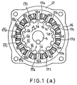
- Fig. 1 (a) is an explanatory view of the structure of a three-phase reluctance-type motor
- Fig. 1 (b) is an explanatory view of the structure of a two-phase reluctance-type motor
- Fig. 2 is a development of the rotor, magnetic poles and armature coils of the three-phase and two-phase motors
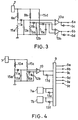
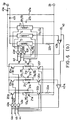
- Figs. 3 and 4 are electric circuits for obtaining position detecting signals from the coils
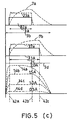
- Fig. 5 is a time chart of position detecting signal curves, armature currents and output torques
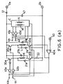
- Fig. 6 is an energization control circuit of the armature coils
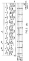
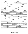
- Fig. 7 is a time chart of the position detecting signals.
- angles are all designated in electrical angle.
- Fig. 1 (a) is an example of the three-phase reluctance-type motor to which this invention is applied, and is a plan view showing the structure of the salient poles of the rotor, the magnetic poles of the stationary armature and the armature coils.
- the width of salient poles 1a, 1b, ... of rotor 1 is 180 degrees, and they are disposed with a phase difference of 360 degrees and an equal pitch.
- Rotor 1 consists of a well-known means of laminating silicon steel plates, with rotating shaft 5 as its axis.
- magnetic poles 16a, 16b, 16c, 16d, 16e, 16f, 16a , 16b , ... 16f are disposed with their width of 180 degrees and at an equal spacing angle.
- the widths of salient poles 1a, 1b, ... and magnetic poles 16a, ... are 180 degrees and equal.
- the number of salient poles is 14, and the number of the magnetic poles is 12.
- Fig. 2 (a) is a development of the reluctance-type three-phase motor in Fig. 1 (a), and is shown till 180 degrees in mechanical angle with the remainder being omitted.
- Salient poles 1a , 1b , ... and magnetic poles 16a , 16b , ... in Fig. 1 (a) are omitted, but these are at positions which are axially symmetrical with salient poles 1a, 1b, ... and magnetic poles 16a, 16b, ... respectively.
- the magnetic attraction forces in the radial direction are balanced, producing an action that the generation of mechanical vibrations and the pressing force to bearings are made very small.
- Coils 10a, l0b and 10c in Fig. 2 (a) are position detecting elements for detecting the positions of salient poles 1a, 1b, ... which are fixed at the stationary armature 16 side in the positions shown, and the coil faces are opposed to the sides of salient poles 1a, 1b, ... via an air-gap therebetween.
- a device for obtaining position detecting signals from coils 10a, 10b and 10c there is shown a device for obtaining position detecting signals from coils 10a, 10b and 10c.
- Coil 10a and resistors 15a, 15b and 15c constitute a bridge circuit, which is adjusted so that it balances when coil 10a is not opposed to salient poles 1a, 1b, ...
- the outputs of the low-pass filters consisting of diode 11a and capacitor 12a and of diode 11b and capacitor 12b are equal, and thus the output of operational amplifier 13 becomes a low level.
- oscillator 7 an oscillation of about 1 megacycles is performed. If coil 10a is opposed to salient poles 1a, 1b, ..., impedance decreases because of iron loss (eddy-current loss plus hysteresis loss), and thus the voltage drop of resistor 15a becomes large, causing the output of operational amplifier 13 to be a high level.
- iron loss eddy-current loss plus hysteresis loss
- the inputs to block circuit 9 are curves 25a, 25b, ... in the time chart of Fig. 7 (a), and the inputs through inverting circuit 13d are curves 26a, 26b, ...
- Block circuits 7a and 7b in Fig. 4 show such bridge circuits which include coils 10b and 10c, respectively.
- Oscillator 7 can commonly be used.
- Block circuit 9 is a circuit which is commonly used by the control circuit of a three-phase, Y-connection semiconductor motor, and is a logical circuit by which electrical signals of rectangular waves having a width of 120 degrees are obtained from terminals 9a, 9b, 9c 9f upon the input- ting of the above-mentioned position detecting signals.
- the outputs of terminals 9a, 9b and 9c are shown as curves 31a, 31b, ..., curves 32a, 32b, ..., and curves 33a, 33b, ..., respectively.
- the outputs of terminals 9d, 9e and 9f are shown as curves 34a, 34b, ..., curves 35a, 35b, ..., and curves 36a, 36b, ..., respectively.
- the phase differences between the output signals of terminals 9a and 9b, between the output signals of terminals 9d and 9e, and between the output signals of terminals 9c and 9f are 180 degrees.
- the output signals of terminals 9a, 9b and 9c sequentially delay by 120 degrees without being superposed, and the output signals of terminals 9d, 9e and 9f sequentially delay by 120 degrees as well.
- a reluctance-type motor has the disadvantages stated below.
- the torque is remarkably large in the initial stage in which salient poles start to oppose magnetic poles, and small in the final stage. Accordingly, there is a defect that the composite torque includes a large ripple torque. To remove such defect, for instance, the following means is effective.
- Curves 14d, 14c, 14b and 14a are the example for armature currents of 0.5 amperes, 1.0 ampere, 1.5 amperes and 2.0 amperes, respectively.
- the width of position detecting signal 31a in the time chart of Fig. 5 (c), as indicated by arrow 3c, is 120 degrees, and when the energization of an armature coil is started at the beginning thereof, the rise is delayed by large inductance as shown by dotted line 7b, and when the armature coil is de-energized at the end of the position detecting signal, the width of the falling portion becomes large because of the discharge of the large stored magnetic energy, as shown by the right end of dotted line 7b.
- the torque decreases as the rise delays, and if the falling portion exceeds the right end of arrow 3d indicating the width of 180 degrees, a counter-torque is caused. Its effect becomes remarkable when the speed is high.
- a reluctance-type motor to enhance the output torque, it is required to increase the number of the magnetic and salient poles in Fig.1 (a) and reduce the opposing air-gap between the two.
- the rise gradient of the exciting current becomes relatively gentle because of the magnetic energy stored in magnetic poles 16a, 16b, ... and salient poles 1a, 1b, ... in Fig. 1, and even if the energization is stopped, the time for the discharge current due to the magnetic energy to disappear is relatively prolonged and thus a large counter-torque occurs.
- circular portion 16 and magnetic poles 16a, 16b, ... are constructed by a well-known means of laminating and solidifying silicon steel plates, and they are fixed to outer casing 17 thereby to form the armature.
- Magnetic core 16 forms a magnetic path. Magnetic core 16 and magnetic poles 16a, 16b, ... constitute the armature.
- the salient poles are 14 in number, and have an equal width and spacing angle.
- the width of magnetic poles 16a, 16b, ... is equal to the salient pole width, and the 12 magnetic poles are disposed with an equal pitch.
- armature coils 17b and 17b When they further rotate, armature coils 17b and 17b are de-energized and armature coils 17d and 17d are energized, so that a torque by salient poles 1d and 1d occurs.
- This provides a three-phase reluctance motor in which rotor 1 is driven in the direction of arrow A.
- Armature coils 17a and 17a are connected in series or in parallel. Armature coils 17b and 17b and the other armature coils 17c, 17c , ... are also connected in a similar manner.
- transistors 20a and 20b, 20c and 20d, and 20e and 20f are inserted, respectively.
- Transistors 20a, 20b, 20c, ... act as switching elements, and other semiconductors having the same effect may be employed instead of them.
- Power is supplied from the positive and negative terminals 2a and 2b of a D.C. power supply.
- transistors 20a and 20b conduct when a high level electrical signal is inputted from terminal 4a, thereby energizing armature coils 17a and 17a .
- transistors 20c and 20d transistors 20e and 20f conduct, thereby energizing armature coils 17c, 17c , 17e and 17e .
- Block circuits D, E and F are the energization control circuits for armature coils 17b, 17b and 17d, 17d and 17f, 17f , and have the same structure as that of the energization control circuit for armature coil 17a, 17a .
- Terminal 40 is a reference voltage for specifying the armature current. By changing the voltage of terminal 40, the output torque can be changed.
- Resistors 22a and 22b are resistors for detecting the armature currents of armature coils 17a, 17a , 17c, 17c , 17e, 17e and 17b, 17b , 17d, 17d , 17f, 17f , respectively.
- the input signals to terminal 4a are position detecting signals 31a, 31b, ... in Fig. 7 (a), and the input signals to terminals 4b and 4c are position detecting signals 32a, 32b, ... and 33a, 33b ..., respectively.
- position detecting signals 36a, 36b, ..., 34a, 34b ..., and 35a, 35b, ... are inputted to terminals 4d, 4e and 4f in Fig. 6 (b), respectively.
- Position detecting signal 31a is shown by same symbol in Fig. 5 (c).
- the armature current increases as shown by dotted line 7b. Because of large inductance in a reluctance-type motor, the rise of dotted line 7b at the beginning of curve 31a is slow.
- the magnetic energy stored in armature coils 17a and 17a is discharged through diode 21a, transistor 20b and resistor 22a, and when the discharge current decreases to a predetermined value, the output returns to a high level again by the hysteresys characteristics of operational amplifier 40a, and transistors 20a and 20b turn on again, thereby increasing the armature current.
- position detecting signal curve 32a of Fig. 5 (b) has already been inputted to terminal 4b of Fig. 6 (b), and thus the stored magnetic energy of armature coils 17a and 17a changes to the magnetic energy of armature coils 17c and 17c , thereby making the rise of the armature current (the left end of dotted line 37b of Fig. 5 (b)) rapid.
- Capacitor 47a is effective when there are timing differences in turn-on and turn-off transistors, but it is not always necessary.
- the width of arrow 37 indicates the width of the fall and rise of dotted lines 37a and 37b. If the width of arrow 37 exceeds a predetermined angle, a counter-torque occurs and the torque also decreases. Since the widths of curves 32a and 33a become small as the speed becomes high, the width of arrow 37 also needs to be made small accordingly. This object is accomplished by diode 41a preventing the stored magnetic energy of armature coils 17a and 17a from flowing into power supply 2a, 2b.
- the width of arrow 37 is about 20 microseconds according to actual measurement, and there is an effect that a rotational speed faster than 100,000 revolutions can be obtained.
- the applied voltage becomes a high voltage due to a counter-electromotive force.
- the limit of high-speed rotation and the output torque are independently controlled by the applied voltage and the reference voltage (the command voltage of the output voltage), respectively.
- the control of the control current by the position detecting signals of armature coils 17c and 17c changes by the chopper action of operational amplifier 40a and AND circuit 43b in Fig. 6 (b) in response to turn-on/off of transistor 20c, as shown by dotted line 37b of Fig. 5 (b), and rapidly falls at the end of curve 32a as shown by a dotted line.
- the armature coils are sequentially energized to generate an output torque.
- the above-mentioned energization mode is referred to as the energization mode of the A-phase.
- Position detecting signals 36a, 36b, ..., 34a, 34b and 35a, 35b, ... in Fig. (a) are inputted to terminals 4d, 4e and 4f in Fig. 6 (b), respectively, thereby to control the energization of armature coils 17b, 17b , 17d, 17d , 17f, 17f included in block circuits D, E and F.
- curves 36a, 34a and 35a are shown. These are adjoining with a width of 120 degrees and delaying in phase by 60 degrees from the upper curves.
- the dotted line portions of curves 36a, 34a and 35a represent armature currents.
- the widths of the rising and falling portions are restricted by diode 41b and capacitor 47b as in the energization mode of the A-phase.
- the energization control of armature coils 17b, 17b , 17d, 17d , 17f, 17f by curves 36a, 36b, ..., 34a, 34b, ... and 35a, 35b, ... is referred to as the energization mode of the B-phase.
- the energization modes of the first, second and third phases are general expressions, they are divided into two in this specification and referred to as the energization modes of the A-phase and B-phase.
- the end of curve 31a is the point of dotted line 42c, and the section between dotted lines 42a and 42c is the energization section of armature coils 17a, 17a .
- the characteristics and section of the flat portion of the torque can be altered by changing the shapes of the opposing magnetic poles and salient poles, and thus it is needed to change the position of dotted line 42a accordingly.
- the width between dotted line 42a and the beginning of the torque curve is 10 to 20 degrees.
- position detecting signal curves 31a, 31b, ... curves 32a, 32b, ... and curves 33a, 33b, ... in Fig. 7 (a) perform the energization control of a width of 120 degrees of armature coils 17a, 17a , 17c, 17c , 17e, 17e , and position detecting signal curves 36a, 36b, ..., curves 34a, 34b, ... and curves 35a, 35b perform the energization control of a width of 120 degrees of armature coils 17b, 17b , 17d, 17d , 17f, 17f .
- the ripple voltage of power supply terminals 2a and 2b in Fig. 6 (b) is not related so much, and thus a capacitor of a small capacity may be used for rectification, and the rectifying capacitor has still smaller capacity for a three-phase A.C. power supply, thereby providing a characteristic feature that the power supply can be simplified.
- Fig. 1 (b) is a plan view of a two-phase reluctance-type motor
- Fig. 2 (b) is a development of the salient poles, magnetic poles and armature coils thereof.
- circular portion 16 and magnetic poles 16a, 16b, ... are made by a well-known means for laminating and solidifying silicon steel plates, and fixed to an outer casing, not shown, to form an armature.
- Magnetic core 16 is a magnetic path.
- Armature coils 17a and 17b are wound around magnetic poles 16a and 16b. Other armature coils are omitted and not shown.
- rotating shaft 5 is supported for rotation, to which rotor 1 is fixed.
- Rotor 1 On the outer periphery of rotor 1, salient poles 1a, 1b, ... are provided and opposed to magnetic poles 16a, 16b, ... with an air-gap of about 0.1 to 0.2 millimeters therebetween. Rotor 1 is also made by the same means as armature 16. The development of this is shown in Fig. 2 (b).
- the salient poles are 10 in number, and have an equal width and spacing angle.
- the width of magnetic poles 16, 16b, ... is equal to the width of the salient poles, and eight magnetic poles are disposed with an equal pitch.
- Arrow 18a shows an exciting polarity of rotating by 90 degrees from the state as shown, and magnetic poles 16b and 16c become the N-pole and magnetic poles 16f and 16g become the S-pole.
- the magnetization of such polarities is to make the counter-torque due to magnetic flux leakage small.
- rotor 1 rotates in the direction of arrow A, providing a two-phase motor.
- the width between the individual magnetic poles is 1.5 times the salient pole width.
- a reluctance-type motor Since a reluctance-type motor has no field magnet, it is required to increase the magnetic flux generated by the magnetic poles even to cover the magnetic flux by the field magnet. Accordingly, the large space between the magnetic poles has important meaning.
- the number of magnetic poles in Fig. 2 (b) is 10, which is larger than the conventional well-known one of this type. Consequently, a counter-torque is generated by the discharge of the magnetic energy stored in the individual magnetic poles by excitation and the output torque becomes large, but there remains a problem of reduction in the rotational speed, thereby making it impossible to put it to practical use.
- the description of the generation of the driving torque of rotor 1 provided above is for an armature coil energization angle of 180 degrees.
- the means of this invention uses an energization angle of 90 degrees, but the rotation principle is completely the same.
- armature coils K and L represent armature coil 17a, 17e and 17c, 17g in Fig. 2 (b), respectively, and the two sets of armature coils are connected in series or parallel.
- transistors 20a, 20b and 20c, 20d are inserted, respectively.
- Transistors 20a, 20b, 20c and 20d act as switching elements, and other semiconductor elements having the same effect may be used instead.
- Power is supplied from the positive and negative terminals 2a and 2b of a D.C. power supply.
- transistors 20a and 20b conduct, whereby armature coil K is energized.
- transistors 20c and 20d When a high-level electrical signal is inputted from terminal 4c, transistors 20c and 20d conduct, whereby armature coil L is energized.
- Coil 8a and 8b in Fig. 2 (b) have the same construction as coil 10a in Fig. 2 (a), and are fixed to the armature side so as to oppose to the side faces of salient poles 1a, 1b, ...
- Coils 8a and 8b are opposed to the side faces of salient poles 1a, 1b, ... through an air-gap as shown in Fig. 2 (b), and this arrangement makes the impedance of the coils small because of iron loss (which includes eddy-current loss, and this loss is large). Coils 8a and 8b are spaced apart by (360 + 90) degrees.
- FIG. 3 an arrangement for obtaining position detecting signals from coils 8a and 8b is shown.
- Coils 8a and 8b, and resistors 15a, 15b, 15c and 15d constitute a bridge circuit.
- the output frequency of oscillator circuit 7 is about 1 megacycles.
- Coils 8a and 8b are air-core coils which are fixed to the stationary armature side, and when opposed to salient poles 1a, 1b, ... in Fig. 2 (b), their impedance decreases because of eddy-current loss and the voltage drop of resistor 15a increases.
- the output of operational amplifier 13a is a rectangular wave output having a width of 180 degrees, and such signal is shown in the time chart of Fig. 7 (b) as curves 70a, 70b ...
- the voltage drop in resistor 15c is inputted to the - terminals of op-erational amplifiers 13a and 13b.
- the output of terminal 6a becomes the above described curves 70a, 70b, ..., and the output of terminal 6b becomes curves 72a, 72b, ..., and the width of each curve is 180 degrees.
- the outputs of terminals 6c and 6d through an inverting circuit are curves 73a, 73b, ... and curves 74a, 74b, ...
- curves 72a, 72b, ... and curves 70a, 70b, ... curves 83a, 83b, ... are obtained by the same means.
- curves 84a, 84b, ... are obtained from curves 72a, 72b, ... and 73a, 73b, and curves 85a, 85b ... from curves 73a, 73b, ... and curves 74a, 74b, ...
- armature coils K and L are armature coils 17a, 17e and 17c, 17g.
- Block circuit c is an energization control circuit including armature coils M and N, and has the completely same construction as those of armature coils K and L.
- Armature coils M and N indicate a series or parallel connecting body of armature coils 17b and 17f, and a similar connecting body of armature coils 17d and 17h, respectively.
- each of the armature coils is energized for 90 degrees in the sequence of armature coil K ⁇ M ⁇ L ⁇ N.
- Position detecting signal curves 82a, 83a, 84a and 85a are shown in Fig. 5 (a) by the same symbols.
- a chopper circuit repeating such cycle is constructed. Since both transistors 20a and 20b turn off at the end of position detecting signal 82a, the stored magnetic energy of armature coil K charges capacitor 47 via diodes 21a and 21b.
- Capacitor 47 may be a capacitor of a small capacity. With a capacitor of a small capacity, the charging current rises more rapidly and the rise of the energization of armature coil M becomes more rapid, and simultaneously the width of the falling portion of armature coil K (the width of arrow 23 in Fig. 5 (a)) can be made small.
- Diode 41 is to prevent the stored magnetic energy from flowing into the power supply and eliminating the above described action.
- a chopper action providing a current value restricted by reference voltage 40 is attained.
- the pulsating current portion of the armature current by the chopper action is omitted and not shown.
- Dotted curves 23a, 23b, 23c and 23d of time chart in Fig. 5 (a) are the armature current curves of armature coils K, M, L and N, respectively.
- the width of arrow 23 can be made 20 microseconds for a motor of a 300-watt output, and thus a high-speed rotation can be achieved.
- a high torque is provided if the height of curve 23a is increased, and to this end, it is only needed to apply a voltage exceeding the counter-electromotive force between terminals 2a and 2b as in the case of an ordinary D.C. motor.
- the width of the section between dotted lines 42a and 42b is 90 degrees.
- the energization mode may be considered to be only the A-phase or the B-phase.
- the same object can also be attained by providing diodes 41, 41a and 41b of Figs. 6 (a) and (b) at the negative electrode 2b side of the power supply.
- An embodiment of the present invention may be utilized for the drive source of industrial equipment as a highly efficient D.C. motor of a large output torque and less torque ripple, and particularly as a servo motor.
Landscapes
- Engineering & Computer Science (AREA)
- Power Engineering (AREA)
- Control Of Electric Motors In General (AREA)
- Control Of Motors That Do Not Use Commutators (AREA)
Claims (3)
- Zwei- oder dreiphasiger Reluktanzmotor, bei welchem bei Erregung der Ankerspulen (z.B. K, 17a) jeder Phase mit einem festen Strom das Drehmoment in der Nähe von 10 bis 20 elektrischen Winkelgraden maximal wird, da die ausgeprägten Pole (1a, ...) des Rotors (1) beginnen, in die Magnetpole (16a, ...) einzutreten, und danach ein flaches Drehmoment nur für einen vorbestimmten Abschnitt erhalten wird, wobei das Welligkeitsdrehmoment des Reluktanzmotors beseitigt ist, bestehend aus:einer Positionsdetektoreinheit mit Positionsdetektorelementen (8a, 8b, 10a bis 10c) zum Detektieren der Positionen von ausgeprägten Rotorpolen (1a ...), durch welche Elemente Positionsdetektorsignale erhalten werden, in denen zeitlich nicht überlagerte kontinuierliche Positionsdetektorsignale mit einer Breite von 90 oder 120 elektrischen Winkelgraden für den zwei- bzw. dreiphasigen Motor enthalten sind,Halbleiterschaltelementen (z.B. 20a, 20b), die an beide Enden jeder Ankerspule (z.B. K, 17a) geschaltet sind,Dioden (z.B. 21a, 21b), die in Sperrichtung zu jeder aus je einem Halbleiterschaltelement und der zugeordneten Ankerspule bestehenden Serienschaltung geschaltet sind,einer Erregungssteuerschaltung, welche die Halbleiterschaltelemente (z.B 20a, 20b) mittels der Positionsdetektorsignale leitend macht, um die Ankerspulen (z.B. K, 17a) sukzessive zu erregen und dadurch ein Ausgangsdrehmoment in einer Richtung zu erzeugen,einer Gleichstromenergiequelle zum Zuführen von Energie zur Erregungssteuerschaltung über eine Diode (z.B. 41), die auf der Seite der positiven oder negativen Elektrode der Energiequelle in Durchlaßrichtung eingesetzt ist,einer Einrichtung zum Einstellen der Fixierungspositionen der Positionsdetektorelemente (8a, 8b, 10a bis 10c) zum Auslösen der Erregung jeder Ankerspule (z.B. K, 17a) dort, wo das Drehmoment maximal wird,einer Zerhackerschaltung (z.B. 40a) zum Halten des Ankerstroms auf einem vorbestimmten Wert undeiner elektrischen Schaltung, welche beim Abschalten der durch ein Positionsdetektorsignal gesteuerten Erregung einer Ankerspule am Ende des Positionsdetektorsignals verhindert, daß die in der Ankerspule gespeicherte magnetische Energie über die in Sperrichtung geschalteten Dioden mittels der auf der Energiequellenseite in Durchlaßrichtung eingesetzten Diode zur Gleichstromenergiequelle rückgekoppelt wird, und die magnetische Energie in gepeicherte magnetische Energie einer als nächste zu erregenden Ankerspule umwandelt, wodurch der Anstieg und Abfall des Ankerstroms schnell gemacht wird.
- Motor nach Anspruch 1, der ein zweiphasiger Reluktanzmotor ist, wobeidie Positionsdetektoreinheit Positionsdetektorelemente (8a, 8b) aufweist, durch welche ein erstes, zweites, drittes und viertes einphasiges Positionsdetektorsignal als die Positionsdetektorsignale erhalten werden, wobeidie Halbleiterschaltelemente (z.B. 20a, 20b) an beide Enden einer ersten, ersten, zweiten und zweiten Ankerspule (z.B. K) geschaltet sind, wenn die Ankerspulen der ersten und zweiten Phase die erste und erste Ankerspule bzw. zweite und zweite Ankerspule bilden, und wobeidie Erregungssteuerschaltung die Halbleiterschaltelemente (z.B. 20a, 20b) mittels des ersten, zweiten, dritten und vierten Positionsdetektorsignals leitend macht, um die erste zweite, erste und zweite Ankerspule (z.B. K) sukzessive zu erregen, wodurch das Ausgangsdrehmoment in einer Richtung erzeugt wird.
- Motor nach Anspruch 1, der ein dreiphasiger Reluktanzmotor ist, wobeidie Positionsdetektoreinheit Positionsdetektorelemente (10a bis 10c) zum Detektieren der Positionen der ausgeprägten Rotorpole (1a, ...) aufweist, durch welche Positionsdetektorsignale eines A-Phasenerregungsmodus, bei welchem ein kontinuierliches erstes, zweites und drittes Positionsdetektorsignal einer Breite von 120 elektrischen Winkelgraden angeordnet sind, die nicht zeitlich überlagert sind, erhalten werden, und durch welche Positionsdetektorsignale eines B-Phasenerregungsmodus, in welchem ein viertes, fünftes und sechstes Positionsdetektorsignal angeordnet sind, die gegenüber dem ersten, zweiten und dritten Positionsdetektorsignal eine Phasendiffferenz von 60 elektrischen Winkelgraden aufweisen, erhalten werden, wobeidie Halbleiterschaltelemente (z.B. 20a, 20b) an beide Enden der ersten, ersten, zweiten, zweiten, dritten und dritten Ankerspule (z.B. 17a) geschaltet sind, wenn die Ankerspulen einer ersten, zweiten und dritten Phase die erste, erste Ankerspule, zweite, zweite Ankerspule und dritte, dritte Ankerspule bilden, wobeidie Erregungssteuerschaltung eine erste Erregungssteuerschaltung, welche die Halbleiterschaltelemente mittels des ersten, zweiten und dritten Positionsdetektorsignals leitend macht, um die erste, zweite bzw. dritte Ankerspule zu erregen, wodurch ein Ausgangsdrehmoment in einer Richtung erzeugt wird, undeine zweite Erregungssteuerschaltung, welche die Halbleiterschaltelemente mittels des vierten, fünften und sechsten Positionsdetektorsignals leitend macht, um die erste, zweite bzw. dritte Ankerspule zu erregen, wodurch ein Drehmoment in der gleichen Richtung erzeugt wird,aufweist, wobei
die Gleichstromenergiequelle zum Zuführen von Energie zur ersten und zweiten Erregungssteuerschaltung über eine erste und zweite Diode (41a, 41b) dient, die auf der Seite der positiven oder negativen Elektrode der Energiequelle eingesetzt sind, und wobeidie elektrische Schaltung beim Abschalten der durch das erste, zweite und dritte Positionsdetektorsignal erregten Ankerspulen am Ende der Positionsdetektorsignale verhindert, daß die in den Ankerspulen gespeicherte magnetische Energie über die in Sperrichtung geschalteten Dioden mittels der ersten Diode zur Gleichstromenergiequelle rückgekoppelt wird, und die magnetische Energie in die gespeicherte magnetische Energie der als nächste zu erregenden Ankerspule umwandelt, und beim Abschalten der durch das vierte, fünfte und sechste Positionsdetektorsignal erregten Ankerspulen am Ende der Positionsdetektorsignale verhindert, daß die in den Ankerspulen gespeicherte magnetische Energie über die in Sperrichtung geschalteten Dioden mittels der zweiten Diode zur Gleichstromenergiequelle rückgekoppelt wird, und die magnetische Energie in die magnetische Energie der als nächste zu erregenden Ankerspule umwandelt, wodurch der Anstieg und Abfall des Ankerstroms schnell gemacht wird.
Applications Claiming Priority (3)
| Application Number | Priority Date | Filing Date | Title |
|---|---|---|---|
| JP200402/89 | 1989-08-03 | ||
| JP1200402A JPH0365094A (ja) | 1989-08-03 | 1989-08-03 | トルクリプルを除去したリラクタンス型電動機 |
| PCT/JP1990/000988 WO1991002402A1 (fr) | 1989-08-03 | 1990-08-02 | Moteur a reluctance |
Publications (3)
| Publication Number | Publication Date |
|---|---|
| EP0436742A1 EP0436742A1 (de) | 1991-07-17 |
| EP0436742A4 EP0436742A4 (en) | 1992-06-03 |
| EP0436742B1 true EP0436742B1 (de) | 1996-10-16 |
Family
ID=16423722
Family Applications (1)
| Application Number | Title | Priority Date | Filing Date |
|---|---|---|---|
| EP90911711A Expired - Lifetime EP0436742B1 (de) | 1989-08-03 | 1990-08-02 | Reluktanzmotor |
Country Status (5)
| Country | Link |
|---|---|
| US (1) | US5138244A (de) |
| EP (1) | EP0436742B1 (de) |
| JP (1) | JPH0365094A (de) |
| DE (1) | DE69028910T2 (de) |
| WO (1) | WO1991002402A1 (de) |
Families Citing this family (24)
| Publication number | Priority date | Publication date | Assignee | Title |
|---|---|---|---|---|
| JPH04109896A (ja) * | 1990-08-28 | 1992-04-10 | Secoh Giken Inc | リラクタンス型電動機のトルクリプル除去装置 |
| JPH04172986A (ja) * | 1990-11-07 | 1992-06-19 | Secoh Giken Inc | 高速3相直流電動機 |
| JPH04183294A (ja) * | 1990-11-15 | 1992-06-30 | Secoh Giken Inc | リラクタンス型電動機 |
| JPH04275096A (ja) * | 1991-02-27 | 1992-09-30 | Secoh Giken Inc | 負荷の数値制御装置 |
| GB9120404D0 (en) * | 1991-09-25 | 1991-11-06 | Switched Reluctance Drives Ltd | Control of switched reluctance machines |
| DE4132881A1 (de) * | 1991-10-03 | 1993-07-29 | Papst Motoren Gmbh & Co Kg | Ansteuerschaltung fuer buerstenlose gleichstrommotoren |
| US5327069A (en) * | 1992-06-19 | 1994-07-05 | General Electric Company | Switched reluctance machine including permanent magnet stator poles |
| EP0601189A4 (de) * | 1992-06-29 | 1995-01-11 | Sekoh Giken Kk | Reluktanzmotor mit nutzbremsung und gleichstrommotor. |
| US5545964A (en) * | 1992-09-24 | 1996-08-13 | Switched Reluctance Drives Ltd. | Control of switched reluctance machines |
| US5404091A (en) * | 1993-05-27 | 1995-04-04 | General Electric Company | Switched reluctance generator system with self-excitation capability during load faults |
| US5381081A (en) * | 1993-05-27 | 1995-01-10 | General Electric Company | Switched reluctance generator for generating AC power |
| EP0758816A4 (de) * | 1994-11-09 | 1998-05-27 | Sekoh Giken Kk | Flacher dreiphasiger reluktanzmotor |
| US5652493A (en) * | 1994-12-08 | 1997-07-29 | Tridelta Industries, Inc. (Magna Physics Division) | Polyphase split-phase switched reluctance motor |
| GB9524893D0 (en) * | 1995-12-05 | 1996-02-07 | Switched Reluctance Drives Ltd | Method and apparatus for producing iron losses in a switched reluctance machine |
| US5661381A (en) * | 1996-02-15 | 1997-08-26 | Dana Corporation | Apparatus for external inductance sensing for variable-reluctance motor commutation |
| GB9818878D0 (en) | 1998-08-28 | 1998-10-21 | Switched Reluctance Drives Ltd | Switched reluctance drive with high power factor |
| JP2000125585A (ja) * | 1998-10-12 | 2000-04-28 | Denso Corp | リラクタンス型電動機 |
| US6483212B1 (en) * | 1999-10-06 | 2002-11-19 | Asmo Co., Ltd. | Reluctance-type electric motor |
| GB0113776D0 (en) * | 2001-06-06 | 2001-07-25 | Switched Reluctance Drives Ltd | Excitation of switched reluctance motors |
| GB0310491D0 (en) * | 2003-05-07 | 2003-06-11 | Switched Reluctance Drives Ltd | Excitation of switched reluctance motors |
| FR2876231B1 (fr) * | 2004-05-06 | 2006-12-22 | Gerard Koehler | Machine dynamo-electrique tournante a reluctance variable a globalisation des circuits magnetiques, electriques et de polarisation et son procede de fabrication |
| KR100784649B1 (ko) * | 2006-04-21 | 2007-12-12 | 경성대학교 산학협력단 | 단상 에스알엠 구동회로 및 구동방법 |
| JP5656424B2 (ja) * | 2010-03-15 | 2015-01-21 | 小松 康廣 | モータドライブ回路 |
| WO2015104821A1 (ja) * | 2014-01-09 | 2015-07-16 | 三菱電機株式会社 | 同期電動機の駆動回路および、その駆動回路により駆動される同期電動機および、その同期電動機を用いた送風機および、その送風機を用いた空気調和機ならびに、同期電動機の駆動方法 |
Citations (2)
| Publication number | Priority date | Publication date | Assignee | Title |
|---|---|---|---|---|
| DE2831997A1 (de) * | 1977-07-20 | 1979-01-25 | Janome Sewing Machine Co Ltd | Steuereinrichtung fuer einen naehmaschinen-impulsmotor |
| EP0427868A1 (de) * | 1989-05-02 | 1991-05-22 | Kabushikigaisha Sekogiken | Elektrischer motor vom reluktanztyp |
Family Cites Families (8)
| Publication number | Priority date | Publication date | Assignee | Title |
|---|---|---|---|---|
| JPS5418018A (en) * | 1977-07-11 | 1979-02-09 | Ricoh Co Ltd | Pulse motor drive circuit |
| US4164696A (en) * | 1977-08-10 | 1979-08-14 | Teletype Corporation | Stepping motor excitation |
| JPS55127889A (en) * | 1979-03-24 | 1980-10-03 | Sony Corp | Motor-driving circuit |
| EP0180815B2 (de) * | 1984-10-19 | 1994-12-28 | Kollmorgen Corporation | Variable Reluktanzmaschine mit variabler Geschwindigkeit |
| IE56528B1 (en) * | 1985-01-15 | 1991-08-28 | John V Byrne | Electrical drive systems incorporating variable reluctance motors |
| US4739203A (en) * | 1986-10-24 | 1988-04-19 | Shicoh Engineering Co. Ltd. | Single-phase brushless motor with cogging features |
| US4739240A (en) * | 1987-04-29 | 1988-04-19 | General Electric Company | Commutator for switched reluctance drive |
| JPH01186193A (ja) * | 1988-01-19 | 1989-07-25 | Secoh Giken Inc | リラクタンス型2相電動機 |
-
1989
- 1989-08-03 JP JP1200402A patent/JPH0365094A/ja active Pending
-
1990
- 1990-08-02 US US07/651,254 patent/US5138244A/en not_active Expired - Fee Related
- 1990-08-02 EP EP90911711A patent/EP0436742B1/de not_active Expired - Lifetime
- 1990-08-02 WO PCT/JP1990/000988 patent/WO1991002402A1/ja not_active Ceased
- 1990-08-02 DE DE69028910T patent/DE69028910T2/de not_active Expired - Fee Related
Patent Citations (2)
| Publication number | Priority date | Publication date | Assignee | Title |
|---|---|---|---|---|
| DE2831997A1 (de) * | 1977-07-20 | 1979-01-25 | Janome Sewing Machine Co Ltd | Steuereinrichtung fuer einen naehmaschinen-impulsmotor |
| EP0427868A1 (de) * | 1989-05-02 | 1991-05-22 | Kabushikigaisha Sekogiken | Elektrischer motor vom reluktanztyp |
Also Published As
| Publication number | Publication date |
|---|---|
| JPH0365094A (ja) | 1991-03-20 |
| DE69028910T2 (de) | 1997-02-13 |
| EP0436742A4 (en) | 1992-06-03 |
| WO1991002402A1 (fr) | 1991-02-21 |
| US5138244A (en) | 1992-08-11 |
| EP0436742A1 (de) | 1991-07-17 |
| DE69028910D1 (de) | 1996-11-21 |
Similar Documents
| Publication | Publication Date | Title |
|---|---|---|
| EP0436742B1 (de) | Reluktanzmotor | |
| US5168190A (en) | Reluctance-type motor | |
| EP0444198B1 (de) | Reluktanzmotor | |
| EP0528046A1 (de) | Motor mit hohre geschwindigkeit | |
| JPH0646593A (ja) | 高速リラクタンス型電動機 | |
| US5214365A (en) | Three-phase reluctance type electric motor | |
| JP2010115086A (ja) | モータシステム及び永久磁石モータの通電方法 | |
| US6369481B1 (en) | Polyphase reluctance motor | |
| JP6393843B1 (ja) | スイッチトリラクタンスモータ | |
| JPH04281390A (ja) | 高速電動機 | |
| JPH0260494A (ja) | リラクタンス型2相電動機 | |
| JPH0947079A (ja) | リラクタンス電動機 | |
| JPH0421391A (ja) | リラクタンス型電動機の正逆転装置 | |
| JPH05219788A (ja) | 高速電動機 | |
| JPH03117394A (ja) | 複数個の電機子を並置したリラクタンス型電動機 | |
| JP2745411B2 (ja) | 高速電動機 | |
| JP2799868B2 (ja) | リラクタンス型電動機 | |
| JPH02101988A (ja) | 3相リラクタンス型電動機 | |
| JPH05308795A (ja) | リラクタンス型3相電動機 | |
| JPH04289795A (ja) | 高速電動機 | |
| JPH05244795A (ja) | リラクタンス型2相高速電動機 | |
| JPH02106192A (ja) | リラクタンス型電動機 | |
| JPH05207784A (ja) | リラクタンス型3相高速電動機 | |
| JPH04161093A (ja) | リラクタンス型電動機 | |
| JPH01186193A (ja) | リラクタンス型2相電動機 |
Legal Events
| Date | Code | Title | Description |
|---|---|---|---|
| PUAI | Public reference made under article 153(3) epc to a published international application that has entered the european phase |
Free format text: ORIGINAL CODE: 0009012 |
|
| 17P | Request for examination filed |
Effective date: 19910423 |
|
| AK | Designated contracting states |
Kind code of ref document: A1 Designated state(s): DE FR GB |
|
| A4 | Supplementary search report drawn up and despatched |
Effective date: 19920421 |
|
| AK | Designated contracting states |
Kind code of ref document: A4 Designated state(s): DE FR GB |
|
| RAP3 | Party data changed (applicant data changed or rights of an application transferred) |
Owner name: KABUSHIKIGAISHA SEKOGIKEN |
|
| 17Q | First examination report despatched |
Effective date: 19940322 |
|
| GRAG | Despatch of communication of intention to grant |
Free format text: ORIGINAL CODE: EPIDOS AGRA |
|
| GRAH | Despatch of communication of intention to grant a patent |
Free format text: ORIGINAL CODE: EPIDOS IGRA |
|
| GRAH | Despatch of communication of intention to grant a patent |
Free format text: ORIGINAL CODE: EPIDOS IGRA |
|
| GRAA | (expected) grant |
Free format text: ORIGINAL CODE: 0009210 |
|
| AK | Designated contracting states |
Kind code of ref document: B1 Designated state(s): DE FR GB |
|
| REF | Corresponds to: |
Ref document number: 69028910 Country of ref document: DE Date of ref document: 19961121 |
|
| ET | Fr: translation filed | ||
| PGFP | Annual fee paid to national office [announced via postgrant information from national office to epo] |
Ref country code: GB Payment date: 19970724 Year of fee payment: 8 |
|
| PGFP | Annual fee paid to national office [announced via postgrant information from national office to epo] |
Ref country code: FR Payment date: 19970811 Year of fee payment: 8 Ref country code: DE Payment date: 19970811 Year of fee payment: 8 |
|
| PLBE | No opposition filed within time limit |
Free format text: ORIGINAL CODE: 0009261 |
|
| STAA | Information on the status of an ep patent application or granted ep patent |
Free format text: STATUS: NO OPPOSITION FILED WITHIN TIME LIMIT |
|
| 26N | No opposition filed | ||
| PG25 | Lapsed in a contracting state [announced via postgrant information from national office to epo] |
Ref country code: GB Free format text: LAPSE BECAUSE OF NON-PAYMENT OF DUE FEES Effective date: 19980802 |
|
| GBPC | Gb: european patent ceased through non-payment of renewal fee |
Effective date: 19980802 |
|
| PG25 | Lapsed in a contracting state [announced via postgrant information from national office to epo] |
Ref country code: FR Free format text: LAPSE BECAUSE OF NON-PAYMENT OF DUE FEES Effective date: 19990430 |
|
| PG25 | Lapsed in a contracting state [announced via postgrant information from national office to epo] |
Ref country code: DE Free format text: LAPSE BECAUSE OF NON-PAYMENT OF DUE FEES Effective date: 19990601 |
|
| REG | Reference to a national code |
Ref country code: FR Ref legal event code: ST |