EP0436093A1 - Ablaufarmatur für eine Brausewanne - Google Patents
Ablaufarmatur für eine Brausewanne Download PDFInfo
- Publication number
- EP0436093A1 EP0436093A1 EP90121882A EP90121882A EP0436093A1 EP 0436093 A1 EP0436093 A1 EP 0436093A1 EP 90121882 A EP90121882 A EP 90121882A EP 90121882 A EP90121882 A EP 90121882A EP 0436093 A1 EP0436093 A1 EP 0436093A1
- Authority
- EP
- European Patent Office
- Prior art keywords
- pot
- cover
- webs
- collar
- metal plate
- Prior art date
- Legal status (The legal status is an assumption and is not a legal conclusion. Google has not performed a legal analysis and makes no representation as to the accuracy of the status listed.)
- Granted
Links
Images

Classifications
-
- E—FIXED CONSTRUCTIONS
- E03—WATER SUPPLY; SEWERAGE
- E03C—DOMESTIC PLUMBING INSTALLATIONS FOR FRESH WATER OR WASTE WATER; SINKS
- E03C1/00—Domestic plumbing installations for fresh water or waste water; Sinks
- E03C1/12—Plumbing installations for waste water; Basins or fountains connected thereto; Sinks
- E03C1/28—Odour seals
- E03C1/29—Odour seals having housing containing dividing wall, e.g. tubular
-
- A—HUMAN NECESSITIES
- A47—FURNITURE; DOMESTIC ARTICLES OR APPLIANCES; COFFEE MILLS; SPICE MILLS; SUCTION CLEANERS IN GENERAL
- A47K—SANITARY EQUIPMENT; ACCESSORIES THEREFOR, e.g. TOILET ACCESSORIES
- A47K1/00—Wash-stands; Appurtenances therefor
- A47K1/14—Stoppers for wash-basins, baths, sinks, or the like
-
- E—FIXED CONSTRUCTIONS
- E03—WATER SUPPLY; SEWERAGE
- E03F—SEWERS; CESSPOOLS
- E03F5/00—Sewerage structures
- E03F5/04—Gullies inlets, road sinks, floor drains with or without odour seals or sediment traps
- E03F5/0407—Floor drains for indoor use
- E03F5/0408—Floor drains for indoor use specially adapted for showers
-
- E—FIXED CONSTRUCTIONS
- E03—WATER SUPPLY; SEWERAGE
- E03F—SEWERS; CESSPOOLS
- E03F5/00—Sewerage structures
- E03F5/04—Gullies inlets, road sinks, floor drains with or without odour seals or sediment traps
- E03F2005/0416—Gullies inlets, road sinks, floor drains with or without odour seals or sediment traps with an odour seal
Definitions
- the invention relates to a drain fitting for a shower tray with the features according to the preamble of the claim.
- Drain fittings of this type are used in shower trays to absorb the water accumulating on the bottom and to pass it on to the sewage pipe on the building side.
- a fitting can be inserted into a hole in the bottom of the shower tray and clamped to the edge of the hole by screwing two cylindrical parts.
- the fitting is closed at the top by a lid, which must be held firmly.
- the cover protrudes so far that the water can flow in all around between the edge of the cover and a collar directly adjoining the tub.
- the drain fitting is equipped with elements for an odor trap.
- the object of the present invention is to be seen in designing a drain fitting of the type in question in such a way that the cover is held firmly on the one hand is that, on the other hand, the protruding cover cannot be the cause of injury if a person slips in the shower tray.
- the cover consists essentially of a soft plastic.
- the cover is made so stable by a firmly connected metal plate that the forces can be transmitted via radial webs, which are made of hard plastic, into the valve anchored in the concrete.
- its edge area is made of soft plastic, which gives way when a person slides against it with his foot and is therefore safe against accidents.
- the entire upper part, of which the lid is a part is connected to the held parts by a catch, which, although it ensures a correct position of the lid, on the other hand loosens itself when it is hit hard, so that also in this regard possible injuries are prevented.
- the individual parts of the drain fitting for a shower tray are pot 10, cylindrical tube 20, insert part 30 and upper part 40.
- the parts consist essentially of plastic.
- an outlet 11 is formed on the side of the cylindrical pot wall.
- a protruding collar 12 is formed on the top of the pot, and a thread 13 is formed on the inside of the pot wall.
- the collar 12 is designed to support a sealing ring 14.
- a cylindrical tube 20 with an external thread 21 is provided, which can be screwed into the pot, almost completely, until an abutment 23 (collar) formed on top of the tube 20 arrives near the collar 12 on the pot.
- a storage space 34 for the odor trap is formed by an insert part 30, namely between an outer wall 31 and an inner wall 33 of this insert part, which is inserted into the tube 22 in the axial direction until a collar 35 of the insert part on a shoulder near the abutment 23 of the Pipe rests.
- side recesses 32 are formed on the insert part 30.
- the annular space 34 (storage space) serves to hold the water necessary for the odor trap.
- an upper part 40 is provided, with a cover 43 which is made of soft plastic and a molded-on baffle 41.
- the baffle 41 protrudes into the annular space 34.
- a plurality of webs 42 made of hard are arranged on the upper part in a radial arrangement Molded plastic, which are supported on the abutment 23 of the tube 20.
- the position of the upper part is positioned by latching in that lugs 42a formed on the webs snap into notches 31a on the insert part.
- the cover is held by the webs such that an annular gap remains between the lower cover surface and the abutment 23, through which the water can flow in on all sides and into the storage space 34. When this is full, the water overflows the inner wall 33, reaches the bottom of the pot, where it can run out at the nozzle 11.
- the cover 43 is made of soft elastic plastic. It is stabilized by an overlying metal plate 44.
- the plate edge 44a is, as can be seen from Fig. 3, bent in profile, so that there is anchoring in the lid. Otherwise, the metal plate 44 does not extend to the edge of the cover, so that the edge area is formed solely by the soft plastic.
- the connection between the cover and the metal plate is further produced by knobs 43a, which consist of the soft plastic of the cover and protrude upward like rivets from openings in the metal plate.
- the supporting webs 43 with locking elements 42a are made of hard plastic and are molded into the soft plastic of the cover, whereby they are raised up to the metal plate 44 so that they can directly absorb and transmit the forces that arise when the metal plate is unscrewed.
Landscapes
- Health & Medical Sciences (AREA)
- Engineering & Computer Science (AREA)
- Public Health (AREA)
- Life Sciences & Earth Sciences (AREA)
- Hydrology & Water Resources (AREA)
- Water Supply & Treatment (AREA)
- Environmental & Geological Engineering (AREA)
- Sink And Installation For Waste Water (AREA)
- Closures For Containers (AREA)
- Bathtubs, Showers, And Their Attachments (AREA)
- Domestic Plumbing Installations (AREA)
- Nozzles (AREA)
- Washing And Drying Of Tableware (AREA)
- Removal Of Water From Condensation And Defrosting (AREA)
Abstract
Description
- Die Erfindung bezieht sich auf eine Ablaufarmatur für eine Brausewanne mit den Merkmalen nach dem Oberbegriff des Patentanspruchs.
- Ablaufarmaturen dieser Art dienen dazu in Brausewannen das bodenseitig anfallende Wasser aufzunehmen und an die gebäudeseitige Abwasserleitung weiterzuführen. Eine solche Armatur kann in ein bodenseitiges Loch der Brausewanne eingesetzt und durch Verschrauben zweier zylindrischer Teile am Lochrand festgeklemmt werden. Die Armatur wird oben durch einen Deckel abgeschlossen, der trittfest gehalten sein muß. Der Deckel steht soweit vor, daß das Wasser ringsum zwischen Deckelrand und einem unmittelbar an die Wanne anschließenden Kragen einfließen kann.
- Die Ablaufarmatur ist mit Elementen für einen Geruchsverschluß ausgerüstet.
- Die Aufgabe der vorliegenden Erfindung ist darin zu sehen, eine Ablaufarmatur der in Rede stehenden Art so auszubilden, daß der Deckel einerseits trittfest gehalten ist, daß jedoch andererseits der überstehende Deckel nicht die Ursache von Verletzungen sein kann, wenn eine Person in der Brausewanne ausrutscht.
- Diese Aufgabe wird durch eine Ablaufarmatur mit den Merkmalen des Patentanspruchs gelöst.
- Bei einer solchen Armatur besteht der Deckel im wesentlichen aus einem weichen Kunststoff. Er ist jedoch durch eine fest damit verbundene Metallplatte so stabil gemacht, daß die Kräfte über radiale Stege, die aus hartem Kunststoff bestehen,in die im Beton verankerte Armatur weitergeleitet werden können. Trotz der stabilen Ausführung des Deckels besteht dessen Randbereich aus weichem Kunststoff, der nachgibt, wenn eine Person mit dem Fuß dagegen rutscht und somit unfallsicher ist. Im übrigen ist das gesamte Oberteil, von dem der Deckel ein Teil ist, mit den festgehaltenen Teilen durch eine Verrastung verbunden, die zwar eine richtige Positionslage des Deckels gewährleistet, andererseits sich jedoch von selbst löst, wenn hart dagegen geschlagen wird, so daß auch diesbezüglich eventuellen Veletzungen vorgebeugt ist.
- Im folgenden wird ein Ausführungsbeispiel der Erfindung beschrieben unter Bezugnahme auf die beiliegenden Zeichnungen.
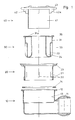
- Fig. 1
- zeigt einen Längsschnitt durch die Einzelteile einer Ablaufarmatur nach der Erfindung in der Anordnung, wie sie montiert werden;
- Fig. 2
- ist ein lotrechter Schnitt durch die funktionsfähig montierte Ablaufarmatur;
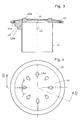
- Fig. 3
- zeigt in vergrößertem Maßstab einen lotrechten Schnitt durch das Oberteil allein;
- Fig. 4
- ist eine Draufsicht auf das Oberteil gemäß Fig. 3;
- Die Einzelteile der Ablaufarmatur für eine Brausewanne sind Topf 10, zylindrisches Rohr 20, Einsatzteil 30 und Oberteil 40. Die Teile bestehen im wesentlichen aus Kunststoff.
- Am Topf 10 ist seitlich an der zylindrischen Topfwand ein Auslaufstutzen 11 angeformt. Oben am Topfrand ist ein vorstehender Kragen 12 angeformt, innen ist an der Topfwand ein Gewinde 13 gebildet. Der Kragen 12 ist zur Auflage für einen Dichtungsring 14 ausgebildet.
- Es ist ein zylindrisches Rohr 20 mit Außengewinde 21 vorgesehen, das in den Topf eingeschraubt werden kann, fast vollständig, bis ein oben am Rohr 20 angeformtes Widerlager 23 (Kragen) in der Nähe des Kragens 12 am Topf gelangt. Wenn die Armatur in ein Loch der Brausewanne eingesetzt ist, dann wird der Lochrand zwischen die Kragen 12 und 23 eingeklemmt, wobei der Dichtungsring 14 zwischengelegt ist und für eine Abdichtung sorgt. Durch die Einklemmung wird die Armatur mit der Wanne 1 verbunden.
- Ein Stauraum 34 für den Geruchsverschluß wird durch ein Einsatzteil 30 gebildet und zwar zwischen einer Außenwand 31 und einer Innenwand 33 dieses Einsatzteiles, das in Achsrichtung in das Rohr 22 eingesetzt wird bis ein Kragen 35 des Einsatzteiles auf einem Absatz in der Nähe des Widerlagers 23 des Rohres aufliegt. Für die achsparallelen Stege 22, die am Rohr 20 zum Ansetzen eines Werkzeuges beim Einschrauben angeformt sind, sind am Einsatzteil 30 seitliche Nischen 32 gebildet. Der Ringraum 34 (Stauraum) dient zur Aufnahme des für den Geruchsverschluß notwendigen Wassers.
- Weiter ist ein Oberteil 40 vorgesehen, mit einem Deckel 43, der aus weichem Kunststoff besteht und einer angeformten Tauchwand 41. Wenn der Deckel positioniert ist, dann ragt die Tauchwand 41 in den Ringraum 34. Am Oberteil sind in radialer Anordnung mehrere Stege 42 aus hartem Kunststoff angeformt, die sich am Widerlager 23 des Rohres 20 abstützen. Dabei ist die Lage des Oberteils durch Verrastung positioniert, indem an den Stegen angeformte Nasen 42a in Kerben 31a am Einsatzteil einrasten. Durch die Stege ist der Deckel so gehalten, daß zwischen der unteren Deckelfläche und dem Widerlager 23 ein Ringspalt bleibt, durch den das Wasser allseitig einfließen kann und in den Stauraum 34 gelangt. Wenn dieser voll ist, überläuft das Wasser die Innenwand 33, gelangt auf den Topfboden, wo es am Stutzen 11 auslaufen kann.
- Der Deckel 43 besteht aus weichem elastischen Kunststoff. Er ist durch eine aufliegende Metallplatte 44 stabilisiert. Der Plattenrand 44a ist, wie aus Fig. 3 ersichtlich, im Profil umgebogen, so daß sich eine Verankerung im Deckel ergibt. Im übrigen erstreckt sind die Metallplatte 44 nicht bis zum Rand des Deckels, so daß der Randbereich allein durch den weichen Kunststoff gebildet wird. Die Verbindung zwischen Deckel und Metallplatte ist weiter durch Noppen 43a hergestellt, die aus dem weichen Kunststoff des Deckels bestehen und wie Niete an Durchbrechungen der Metallplatte nach oben vorstehen.
- Die zur Abstützung dienenden Stege 43 mit Rastelementen 42a bestehen aus hartem Kunststoff und sind in den weichen Kunststoff des Deckels eingeformt, wobei sie bis zur Metallplatte 44 hochgeführt sind, so daß sie unmittelbar die Kräfte die beim Aufdrehen entstehen von der Metallplatte aufnehmen und weiterleiten können.
Claims (1)
- Ablaufarmatur für eine Brausewanne mit den Merkmalen:- sie besteht aus einem Topf mit einem Kragen;- es ist ein Zylinder in den Topf eingeschraubt, mit einem Kragen, der zusammen mit dem Kragen am Topf zum Festklemmen der Armatur an der Brausewanne dient;- der Topf nimmt einen Einsatz auf, mit einem Ringraum, der als Stauraum für den Geruchsverschluß dient;- es ist ein Oberteil vorgesehen, bestehend aus einem Deckel, der sich mit radialen Stegen am Kragen des Zylinders abstützt, und der mit einer in den Ringraum ragenden Tauchwand versehen ist;
gekennzeichnet durch die nachfolgend genannten Merkmale:
- der Deckel (43) besteht aus einem weichen elastischen Kunststoff und ist mit einer eingeformten Metallplatte (44) abgedeckt, wobei jedoch der Deckel-Randbereich nicht durch Metall abgedeckt ist;- die Stege (42) bestehen aus hartem Kunststoff, sind in den weichen Kunststoff des Deckels eingeformt und erstrecken sich bis zur Metallplatte (44);- an den Stegen (42) sind Nasen (42a) gebildet, die mit entsprechenden Gegenelementen (31a) an der Außenwand des Einsatzteils eine lösbare Rastverbindung bilden.
Applications Claiming Priority (2)
| Application Number | Priority Date | Filing Date | Title |
|---|---|---|---|
| DE4000104 | 1990-01-04 | ||
| DE4000104A DE4000104A1 (de) | 1990-01-04 | 1990-01-04 | Ablaufarmatur fuer eine brausewanne |
Publications (2)
| Publication Number | Publication Date |
|---|---|
| EP0436093A1 true EP0436093A1 (de) | 1991-07-10 |
| EP0436093B1 EP0436093B1 (de) | 1994-08-03 |
Family
ID=6397597
Family Applications (1)
| Application Number | Title | Priority Date | Filing Date |
|---|---|---|---|
| EP90121882A Expired - Lifetime EP0436093B1 (de) | 1990-01-04 | 1990-11-15 | Ablaufarmatur für eine Brausewanne |
Country Status (4)
| Country | Link |
|---|---|
| EP (1) | EP0436093B1 (de) |
| AT (1) | ATE109535T1 (de) |
| DE (2) | DE4000104A1 (de) |
| ES (1) | ES2060901T3 (de) |
Cited By (8)
| Publication number | Priority date | Publication date | Assignee | Title |
|---|---|---|---|---|
| EP0612893A1 (de) * | 1993-02-24 | 1994-08-31 | Ab Sjöbo Bruk | Einstellbare Vorrichtung für Bodenabläufe |
| WO1998054416A1 (en) * | 1997-05-27 | 1998-12-03 | Senova Ab | A floor drain |
| DE20101787U1 (de) * | 2001-02-02 | 2002-06-13 | Franz Viegener II GmbH & Co. KG, 57439 Attendorn | Ablauf |
| EP1574629A1 (de) * | 2004-03-12 | 2005-09-14 | Geberit Technik Ag | Ablaufarmatur für eine sanitäre Apparatur, insbesondere Duschwanne |
| EP1837447A1 (de) * | 2006-03-25 | 2007-09-26 | Dallmer GmbH & Co. KG | Urinal |
| US7893193B2 (en) | 2005-05-20 | 2011-02-22 | Solvay (Société Anonyme) | Method for making a chlorohydrin |
| WO2018208257A2 (en) | 2016-12-23 | 2018-11-15 | Eczacibaşi Yapi Gereçleri̇ Sanayi̇ Ve Ti̇caret Anoni̇m Şi̇rketi̇ | A discharge system |
| EP3805473A3 (de) * | 2019-10-09 | 2021-07-07 | ACO Severin Ahlmann GmbH & Co. KG | Geruchsverschluss, ablauftopf und ablaufsystem |
Families Citing this family (5)
| Publication number | Priority date | Publication date | Assignee | Title |
|---|---|---|---|---|
| DK18890D0 (da) * | 1990-01-24 | 1990-01-24 | Joergen Mosbaek Johannessen | Gulvafloeb og afloebsrender med sugevirkning |
| DE4206903A1 (de) * | 1992-03-05 | 1993-09-23 | Dallmer Gmbh & Co | Ablaufarmatur fuer brausebecken oder spuelbecken |
| DE202011109947U1 (de) * | 2011-01-21 | 2012-08-01 | Franz Kaldewei Gmbh & Co. Kg | Sanitärwanne |
| DE102019131566B4 (de) * | 2019-11-22 | 2021-07-01 | Viega Technology Gmbh & Co. Kg | Ablaufarmatur, insbesondere für eine Duschwanne oder in Form eines Bodenablaufs |
| DE102024101552A1 (de) * | 2024-01-19 | 2025-07-24 | Bette Gesellschaft mit beschränkter Haftung & Co. K.G. | Sanitärinstallation |
Citations (5)
| Publication number | Priority date | Publication date | Assignee | Title |
|---|---|---|---|---|
| DE318264C (de) * | ||||
| GB753796A (en) * | 1953-07-27 | 1956-08-01 | Press Plugs Pty Ltd | Improvements in or relating to closure devices for orifices |
| DE2639962A1 (de) * | 1975-09-04 | 1977-03-17 | Chantrieux Jacques | Siphon fuer sanitaerobjekte |
| GB1591369A (en) * | 1977-09-21 | 1981-06-17 | Taylor G | Waste trap |
| CH651610A5 (en) * | 1980-01-17 | 1985-09-30 | Bernhard Kessel | Water-discharge tank |
Family Cites Families (3)
| Publication number | Priority date | Publication date | Assignee | Title |
|---|---|---|---|---|
| AT260118B (de) * | 1964-10-14 | 1968-02-12 | Rokal Gmbh | Mittels Hebelgestänges od. dgl. anhebbarer Ventilstopfen für die Auslaßöffnung eines Waschbeckens od. dgl. |
| FR2502210A1 (fr) * | 1981-10-29 | 1982-09-24 | Dalphinet Raymond | Clapet amovible d'obturation pour bonde d'appareil sanitaire |
| DE8813543U1 (de) * | 1988-10-28 | 1988-12-15 | Fa. Franz Viegener Ii, 5952 Attendorn | Ablaufarmatur, vorzugsweise für Duschwannen |
-
1990
- 1990-01-04 DE DE4000104A patent/DE4000104A1/de not_active Withdrawn
- 1990-11-15 AT AT90121882T patent/ATE109535T1/de not_active IP Right Cessation
- 1990-11-15 EP EP90121882A patent/EP0436093B1/de not_active Expired - Lifetime
- 1990-11-15 DE DE59006695T patent/DE59006695D1/de not_active Expired - Fee Related
- 1990-11-15 ES ES90121882T patent/ES2060901T3/es not_active Expired - Lifetime
Patent Citations (5)
| Publication number | Priority date | Publication date | Assignee | Title |
|---|---|---|---|---|
| DE318264C (de) * | ||||
| GB753796A (en) * | 1953-07-27 | 1956-08-01 | Press Plugs Pty Ltd | Improvements in or relating to closure devices for orifices |
| DE2639962A1 (de) * | 1975-09-04 | 1977-03-17 | Chantrieux Jacques | Siphon fuer sanitaerobjekte |
| GB1591369A (en) * | 1977-09-21 | 1981-06-17 | Taylor G | Waste trap |
| CH651610A5 (en) * | 1980-01-17 | 1985-09-30 | Bernhard Kessel | Water-discharge tank |
Cited By (10)
| Publication number | Priority date | Publication date | Assignee | Title |
|---|---|---|---|---|
| EP0612893A1 (de) * | 1993-02-24 | 1994-08-31 | Ab Sjöbo Bruk | Einstellbare Vorrichtung für Bodenabläufe |
| WO1998054416A1 (en) * | 1997-05-27 | 1998-12-03 | Senova Ab | A floor drain |
| DE20101787U1 (de) * | 2001-02-02 | 2002-06-13 | Franz Viegener II GmbH & Co. KG, 57439 Attendorn | Ablauf |
| EP1574629A1 (de) * | 2004-03-12 | 2005-09-14 | Geberit Technik Ag | Ablaufarmatur für eine sanitäre Apparatur, insbesondere Duschwanne |
| US7893193B2 (en) | 2005-05-20 | 2011-02-22 | Solvay (Société Anonyme) | Method for making a chlorohydrin |
| EP1837447A1 (de) * | 2006-03-25 | 2007-09-26 | Dallmer GmbH & Co. KG | Urinal |
| WO2018208257A2 (en) | 2016-12-23 | 2018-11-15 | Eczacibaşi Yapi Gereçleri̇ Sanayi̇ Ve Ti̇caret Anoni̇m Şi̇rketi̇ | A discharge system |
| EP3559357A4 (de) * | 2016-12-23 | 2020-08-05 | Eczacibasi Yapi Gereçleri Sanayi Ve Ticaret Anonim Sirketi | Entladungssystem |
| EP3805473A3 (de) * | 2019-10-09 | 2021-07-07 | ACO Severin Ahlmann GmbH & Co. KG | Geruchsverschluss, ablauftopf und ablaufsystem |
| EP4105398A1 (de) * | 2019-10-09 | 2022-12-21 | ACO Ahlmann SE & Co. KG | Ablauftopf |
Also Published As
| Publication number | Publication date |
|---|---|
| ES2060901T3 (es) | 1994-12-01 |
| ATE109535T1 (de) | 1994-08-15 |
| DE59006695D1 (de) | 1994-09-08 |
| EP0436093B1 (de) | 1994-08-03 |
| DE4000104A1 (de) | 1991-07-11 |
Similar Documents
| Publication | Publication Date | Title |
|---|---|---|
| EP0436093B1 (de) | Ablaufarmatur für eine Brausewanne | |
| DE60218879T2 (de) | Ablaufanordnung mit stopfenführung als installationshilfe | |
| EP1782721B1 (de) | Duschtassenelement mit einer Ablaufrinne | |
| EP0455998A1 (de) | Sanitäre Armatur | |
| EP0446177A1 (de) | Überlauf- und Ablaufgarnitur für sanitäre Apparate | |
| DE9312982U1 (de) | Tischspringbrunnen | |
| DE102017129108A1 (de) | System aus einem Geruchsverschluss und einem Aufnahmekörper sowie ein Geruchsverschluss | |
| EP2808458B1 (de) | Wasserablaufvorrichtung für eine Dusche und Duschbodenelement | |
| EP0558979A1 (de) | Ablaufarmatur für Brausebecken | |
| DE4226685C5 (de) | Überlaufarmatur für eine Bade- oder Duschwanne | |
| EP4283059B1 (de) | Verlegekasten zur aufnahme einer ablaufgarnitur | |
| DE202008001013U1 (de) | Ablaufarmatur, insbesondere für Dusch- oder Badewannen | |
| DE10360310A1 (de) | Ablaufvorrichtung | |
| EP1936047B1 (de) | Ablaufgarnitur für einen Sanitärartikel | |
| DE10201347A1 (de) | Einlaufvorrichtung für die Abführung von Regenwasser von einem Dach | |
| EP1798352A1 (de) | Ablauf für sanitäre Apparate | |
| DE102010044940B4 (de) | Abwasserablauf mit Geruchsverschluss | |
| EP0480277B1 (de) | Formgeschäumter Wannenträger aus Hartschaumstoff für Bade- oder Duschwannen | |
| DE19649239A1 (de) | Ablaufarmatur mit einstellbarem Tauchrohr und geschweißtem Gehäuse | |
| EP1574629B1 (de) | Ablaufarmatur für eine sanitäre Apparatur, insbesondere Duschwanne | |
| EP1775395A1 (de) | Ablaufarmatur für sanitäre Anlagen | |
| DE9214996U1 (de) | Ablaufarmatur für eine Brausewanne | |
| EP0011154B1 (de) | Aus Kunststoffteilen zusammensetzbarer Bodenablauf mit Geruchverschluss | |
| CH651610A5 (en) | Water-discharge tank | |
| EP4071312B1 (de) | Vorrichtung für eine im boden eines raumes angeordnete ablaufvorrichtung sowie ablaufvorrichtung mit einer derartigen vorrichtung |
Legal Events
| Date | Code | Title | Description |
|---|---|---|---|
| PUAI | Public reference made under article 153(3) epc to a published international application that has entered the european phase |
Free format text: ORIGINAL CODE: 0009012 |
|
| AK | Designated contracting states |
Kind code of ref document: A1 Designated state(s): AT BE CH DE DK ES FR GB GR IT LI NL SE |
|
| 17P | Request for examination filed |
Effective date: 19910606 |
|
| 17Q | First examination report despatched |
Effective date: 19910904 |
|
| GRAA | (expected) grant |
Free format text: ORIGINAL CODE: 0009210 |
|
| AK | Designated contracting states |
Kind code of ref document: B1 Designated state(s): AT BE CH DE DK ES FR GB GR IT LI NL SE |
|
| PG25 | Lapsed in a contracting state [announced via postgrant information from national office to epo] |
Ref country code: DK Effective date: 19940803 Ref country code: GR Free format text: LAPSE BECAUSE OF FAILURE TO SUBMIT A TRANSLATION OF THE DESCRIPTION OR TO PAY THE FEE WITHIN THE PRESCRIBED TIME-LIMIT Effective date: 19940803 |
|
| REF | Corresponds to: |
Ref document number: 109535 Country of ref document: AT Date of ref document: 19940815 Kind code of ref document: T |
|
| REF | Corresponds to: |
Ref document number: 59006695 Country of ref document: DE Date of ref document: 19940908 |
|
| ITF | It: translation for a ep patent filed | ||
| PG25 | Lapsed in a contracting state [announced via postgrant information from national office to epo] |
Ref country code: SE Effective date: 19941103 |
|
| REG | Reference to a national code |
Ref country code: ES Ref legal event code: FG2A Ref document number: 2060901 Country of ref document: ES Kind code of ref document: T3 |
|
| ET | Fr: translation filed | ||
| GBT | Gb: translation of ep patent filed (gb section 77(6)(a)/1977) |
Effective date: 19941107 |
|
| PLBE | No opposition filed within time limit |
Free format text: ORIGINAL CODE: 0009261 |
|
| STAA | Information on the status of an ep patent application or granted ep patent |
Free format text: STATUS: NO OPPOSITION FILED WITHIN TIME LIMIT |
|
| 26N | No opposition filed | ||
| REG | Reference to a national code |
Ref country code: GB Ref legal event code: IF02 |
|
| PGFP | Annual fee paid to national office [announced via postgrant information from national office to epo] |
Ref country code: ES Payment date: 20041104 Year of fee payment: 15 |
|
| PGFP | Annual fee paid to national office [announced via postgrant information from national office to epo] |
Ref country code: BE Payment date: 20041125 Year of fee payment: 15 |
|
| PGFP | Annual fee paid to national office [announced via postgrant information from national office to epo] |
Ref country code: AT Payment date: 20051011 Year of fee payment: 16 |
|
| PGFP | Annual fee paid to national office [announced via postgrant information from national office to epo] |
Ref country code: FR Payment date: 20051013 Year of fee payment: 16 |
|
| PGFP | Annual fee paid to national office [announced via postgrant information from national office to epo] |
Ref country code: CH Payment date: 20051018 Year of fee payment: 16 Ref country code: GB Payment date: 20051018 Year of fee payment: 16 Ref country code: NL Payment date: 20051018 Year of fee payment: 16 |
|
| PG25 | Lapsed in a contracting state [announced via postgrant information from national office to epo] |
Ref country code: IT Free format text: LAPSE BECAUSE OF NON-PAYMENT OF DUE FEES;WARNING: LAPSES OF ITALIAN PATENTS WITH EFFECTIVE DATE BEFORE 2007 MAY HAVE OCCURRED AT ANY TIME BEFORE 2007. THE CORRECT EFFECTIVE DATE MAY BE DIFFERENT FROM THE ONE RECORDED. Effective date: 20051115 |
|
| PG25 | Lapsed in a contracting state [announced via postgrant information from national office to epo] |
Ref country code: ES Free format text: LAPSE BECAUSE OF NON-PAYMENT OF DUE FEES Effective date: 20051116 |
|
| PG25 | Lapsed in a contracting state [announced via postgrant information from national office to epo] |
Ref country code: BE Free format text: LAPSE BECAUSE OF NON-PAYMENT OF DUE FEES Effective date: 20051130 |
|
| PG25 | Lapsed in a contracting state [announced via postgrant information from national office to epo] |
Ref country code: AT Free format text: LAPSE BECAUSE OF NON-PAYMENT OF DUE FEES Effective date: 20061115 |
|
| PG25 | Lapsed in a contracting state [announced via postgrant information from national office to epo] |
Ref country code: LI Free format text: LAPSE BECAUSE OF NON-PAYMENT OF DUE FEES Effective date: 20061130 Ref country code: CH Free format text: LAPSE BECAUSE OF NON-PAYMENT OF DUE FEES Effective date: 20061130 |
|
| REG | Reference to a national code |
Ref country code: ES Ref legal event code: FD2A Effective date: 20051116 |
|
| PG25 | Lapsed in a contracting state [announced via postgrant information from national office to epo] |
Ref country code: NL Free format text: LAPSE BECAUSE OF NON-PAYMENT OF DUE FEES Effective date: 20070601 |
|
| REG | Reference to a national code |
Ref country code: CH Ref legal event code: PL |
|
| GBPC | Gb: european patent ceased through non-payment of renewal fee |
Effective date: 20061115 |
|
| NLV4 | Nl: lapsed or anulled due to non-payment of the annual fee |
Effective date: 20070601 |
|
| REG | Reference to a national code |
Ref country code: FR Ref legal event code: ST Effective date: 20070731 |
|
| PG25 | Lapsed in a contracting state [announced via postgrant information from national office to epo] |
Ref country code: GB Free format text: LAPSE BECAUSE OF NON-PAYMENT OF DUE FEES Effective date: 20061115 |
|
| BERE | Be: lapsed |
Owner name: *DALLMER G.M.B.H. & CO. K.G. Effective date: 20051130 |
|
| PG25 | Lapsed in a contracting state [announced via postgrant information from national office to epo] |
Ref country code: FR Free format text: LAPSE BECAUSE OF NON-PAYMENT OF DUE FEES Effective date: 20061130 |
|
| PGFP | Annual fee paid to national office [announced via postgrant information from national office to epo] |
Ref country code: DE Payment date: 20080104 Year of fee payment: 18 |
|
| PG25 | Lapsed in a contracting state [announced via postgrant information from national office to epo] |
Ref country code: DE Free format text: LAPSE BECAUSE OF NON-PAYMENT OF DUE FEES Effective date: 20090603 |