EP0436064B1 - Lampenfassung zur Aufnahme einer Glühlampe - Google Patents
Lampenfassung zur Aufnahme einer Glühlampe Download PDFInfo
- Publication number
- EP0436064B1 EP0436064B1 EP90114187A EP90114187A EP0436064B1 EP 0436064 B1 EP0436064 B1 EP 0436064B1 EP 90114187 A EP90114187 A EP 90114187A EP 90114187 A EP90114187 A EP 90114187A EP 0436064 B1 EP0436064 B1 EP 0436064B1
- Authority
- EP
- European Patent Office
- Prior art keywords
- contact element
- outer sleeve
- holder
- region
- lamp
- Prior art date
- Legal status (The legal status is an assumption and is not a legal conclusion. Google has not performed a legal analysis and makes no representation as to the accuracy of the status listed.)
- Expired - Lifetime
Links
- 229920003023 plastic Polymers 0.000 claims description 6
- 239000004033 plastic Substances 0.000 claims description 6
- 239000000463 material Substances 0.000 claims description 4
- 239000011521 glass Substances 0.000 description 9
- 229910052751 metal Inorganic materials 0.000 description 4
- 238000004519 manufacturing process Methods 0.000 description 3
- 239000002184 metal Substances 0.000 description 3
- 238000001746 injection moulding Methods 0.000 description 2
- 238000000926 separation method Methods 0.000 description 2
- 239000002131 composite material Substances 0.000 description 1
- 238000005192 partition Methods 0.000 description 1
- 238000001721 transfer moulding Methods 0.000 description 1
Images

Classifications
-
- H—ELECTRICITY
- H01—ELECTRIC ELEMENTS
- H01R—ELECTRICALLY-CONDUCTIVE CONNECTIONS; STRUCTURAL ASSOCIATIONS OF A PLURALITY OF MUTUALLY-INSULATED ELECTRICAL CONNECTING ELEMENTS; COUPLING DEVICES; CURRENT COLLECTORS
- H01R13/00—Details of coupling devices of the kinds covered by groups H01R12/70 or H01R24/00 - H01R33/00
- H01R13/02—Contact members
- H01R13/03—Contact members characterised by the material, e.g. plating, or coating materials
- H01R13/035—Plated dielectric material
-
- H—ELECTRICITY
- H01—ELECTRIC ELEMENTS
- H01R—ELECTRICALLY-CONDUCTIVE CONNECTIONS; STRUCTURAL ASSOCIATIONS OF A PLURALITY OF MUTUALLY-INSULATED ELECTRICAL CONNECTING ELEMENTS; COUPLING DEVICES; CURRENT COLLECTORS
- H01R33/00—Coupling devices specially adapted for supporting apparatus and having one part acting as a holder providing support and electrical connection via a counterpart which is structurally associated with the apparatus, e.g. lamp holders; Separate parts thereof
- H01R33/05—Two-pole devices
- H01R33/06—Two-pole devices with two current-carrying pins, blades or analogous contacts, having their axes parallel to each other
- H01R33/09—Two-pole devices with two current-carrying pins, blades or analogous contacts, having their axes parallel to each other for baseless lamp bulb
-
- H—ELECTRICITY
- H01—ELECTRIC ELEMENTS
- H01R—ELECTRICALLY-CONDUCTIVE CONNECTIONS; STRUCTURAL ASSOCIATIONS OF A PLURALITY OF MUTUALLY-INSULATED ELECTRICAL CONNECTING ELEMENTS; COUPLING DEVICES; CURRENT COLLECTORS
- H01R13/00—Details of coupling devices of the kinds covered by groups H01R12/70 or H01R24/00 - H01R33/00
- H01R13/02—Contact members
- H01R13/22—Contacts for co-operating by abutting
- H01R13/24—Contacts for co-operating by abutting resilient; resiliently-mounted
- H01R13/2407—Contacts for co-operating by abutting resilient; resiliently-mounted characterized by the resilient means
- H01R13/2414—Contacts for co-operating by abutting resilient; resiliently-mounted characterized by the resilient means conductive elastomers
-
- H—ELECTRICITY
- H01—ELECTRIC ELEMENTS
- H01R—ELECTRICALLY-CONDUCTIVE CONNECTIONS; STRUCTURAL ASSOCIATIONS OF A PLURALITY OF MUTUALLY-INSULATED ELECTRICAL CONNECTING ELEMENTS; COUPLING DEVICES; CURRENT COLLECTORS
- H01R33/00—Coupling devices specially adapted for supporting apparatus and having one part acting as a holder providing support and electrical connection via a counterpart which is structurally associated with the apparatus, e.g. lamp holders; Separate parts thereof
- H01R33/05—Two-pole devices
- H01R33/06—Two-pole devices with two current-carrying pins, blades or analogous contacts, having their axes parallel to each other
Definitions
- the invention relates to a lamp holder for receiving a glass base lamp according to the preamble of claim 1.
- the prior art is based on a lamp holder (FR-A-2 356 292), in which an outer sleeve and an inner separating area are formed as a one-piece unit which isolates the contact elements from one another.
- These contact elements are costly made of sheet metal and have to be arranged inside the lamp socket with increased assembly effort.
- lamp holders (DE-AS 14 64 176, DE-AS 23 10 151) are constructed such that guides made of sheet metal are arranged within a sleeve, which have both spring elements and curved tracks. This also results in considerable assembly and cost expenditure for the production and arrangement of the individual metal elements in the interior of such a lamp holder.
- the prior art also includes electrically conductive plastic, which contains a conductive component and can be processed, for example, by injection molding or transfer molding (DE-A-34 09 953, DE-A-33 05 401, DE-A 32 45 578, DE-A-32 38 246). These electrically conductive plastics can be used as composite bodies.
- FIG. 1 Another prior art is a lamp holder for light bulbs with free wire ends or for light-emitting diodes (DE 37 27 515 A1).
- An outer tube and an inner tube are used here, the free wire end of the light bulb being clamped to the outer tube by means of a clamping sleeve.
- An insulating layer is arranged between the outer tube and the inner tube in order to separate the conductive outer tube from the conductive inner tube. Both tubes are smooth and require a special position-stabilizing connection, with the clamping sleeve also having to undergo additional fixation.
- the present invention has for its object to design a lamp holder of the type mentioned in such a way that a simple, cost-saving structure is created, and in addition, the assembly effort should be kept low.
- both contact elements each consist of an electrically conductive plastic material and the socket has an outer sleeve enclosing the contact elements and an inner separating region arranged inside the socket and isolating the contact elements from one another, eliminates the cost-intensive and expensive manufacture of the contact elements made of metal.
- the outer sleeve and the inner separating area can be designed as a one-piece unit, the contact elements also being sleeve-like and can be inserted into the space between the outer sleeve and the inner separating area and into the interior of the inner area. There is a lock in this position.
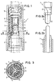
- the lamp holder 1 consists of two sleeve-like contact elements 8 and 9, an outer sleeve 10 enclosing these contact elements and an inner separating area 11 arranged inside the socket 1 and isolating the contact elements 8, 9 from one another.
- the outer sleeve 10 and the inner separating area 11 formed as a one-piece unit.
- the two contact elements 8 and 9 consist of an electrically conductive plastic material and are each designed like a sleeve.
- the outer sleeve 10 is z. B. connected to the inner separation region 11 via three webs 12, 13, 14 arranged distributed over the circumference.
- the outer sleeve-like contact element 9 is inserted in the intermediate space 15 between the outer sleeve 10 and the inner separating area 11.
- the inner contact element 8 is inserted into the interior 16 of the inner separation region 11. Both contact elements 8 and 9 are arranged captively within the respective space 15 or 16.
- both contact elements 8 and 9 designed like sleeves, each have at least one stop surface 19 or 20. These stop surfaces 19 and 20 can rest against a corresponding shoulder 17 and 18 of the outer sleeve 10 and the inner separating region 11.
- the outer contact element 9 has at least one in the relevant web 12, 13 or 14 between the outer sleeve 10 and the inner separating region 11 of the slot 21 according to FIG. 4.
- the outer contact element 9 has a neck-like bearing zone 23, which ends in a conical shape 24 on the end face.
- This neck-like storage zone 23 is adjusted to the diameter of the storage area 22 of the glass base lamp 2 to be held according to FIG. 2a.
- the bearing zone 23 can have either cylindrical shape 23 or profiled shape 23 '. It can also be seen from both figures that the outer contact element has at least one stop surface 19.
- the inner contact element 8 shows the inner contact element 8. This has two blind holes 26 and 27 separated from one another by a partition 40.
- the blind hole 27 is preferably divided by at least one slot 28.
- the diameter of the blind hole 26 is adjusted to the diameter of the lamp base 25 of the glass base lamp 2 according to FIG. 2a; the diameter of the blind hole 27 of the inner contact element 8 is adjusted to the diameter of the lead 6 of the current-carrying lead part 5.
- the lamp holder 1 according to FIG. 1, which is composed of the outer sleeve 10, the outer contact element 9, the inner contact element 8 and the inner separating region 11, is mounted in the correct manner, the glass base lamp 2 can be inserted from above, the bearing region 22 of the glass base lamp 2 being in the elastic bearing zone 23 of the outer contact element 9 stores.
- the contact wire 3 acts on the inner contact element 8; the other contact wire 4 acts on the outer contact element 9.
- the current-carrying lead part 5 can be inserted from below into the lamp holder according to the invention, the lead 6 being embedded in the lower blind hole 27 of the inner contact element 8.
- the other lead 7 acts on the inner wall of the outer contact element 9 with its outer surface. A connection between the contact wires 3 and 4 of the glass base lamp 2 and the leads 6 and 7 of the current-carrying lead part 5 is thus established in a functionally correct manner.
- the two contact elements 8 and 9 consist of electrically conductive plastic material, the overall design is considerably simplified with cost-saving assembly.
- the abutment surfaces 19 and 20 of the inner and outer contact elements 8, 9 abut the corresponding shoulders 17 and 18 of the outer sleeve 10 and the inner separating area 11, respectively. This provides an exact adjustment of the individual elements within the outer sleeve 10 of the lamp holder 1 according to the invention.
Landscapes
- Fastening Of Light Sources Or Lamp Holders (AREA)
- Connecting Device With Holders (AREA)
- Arrangements Of Lighting Devices For Vehicle Interiors, Mounting And Supporting Thereof, Circuits Therefore (AREA)
Priority Applications (1)
| Application Number | Priority Date | Filing Date | Title |
|---|---|---|---|
| EP93111870A EP0570991B1 (de) | 1989-12-01 | 1990-07-24 | Lampenfassung |
Applications Claiming Priority (2)
| Application Number | Priority Date | Filing Date | Title |
|---|---|---|---|
| DE3939830A DE3939830C1 (enExample) | 1989-12-01 | 1989-12-01 | |
| DE3939830 | 1989-12-01 |
Related Child Applications (1)
| Application Number | Title | Priority Date | Filing Date |
|---|---|---|---|
| EP93111870.7 Division-Into | 1993-07-23 |
Publications (2)
| Publication Number | Publication Date |
|---|---|
| EP0436064A1 EP0436064A1 (de) | 1991-07-10 |
| EP0436064B1 true EP0436064B1 (de) | 1994-03-09 |
Family
ID=6394638
Family Applications (2)
| Application Number | Title | Priority Date | Filing Date |
|---|---|---|---|
| EP90114187A Expired - Lifetime EP0436064B1 (de) | 1989-12-01 | 1990-07-24 | Lampenfassung zur Aufnahme einer Glühlampe |
| EP93111870A Expired - Lifetime EP0570991B1 (de) | 1989-12-01 | 1990-07-24 | Lampenfassung |
Family Applications After (1)
| Application Number | Title | Priority Date | Filing Date |
|---|---|---|---|
| EP93111870A Expired - Lifetime EP0570991B1 (de) | 1989-12-01 | 1990-07-24 | Lampenfassung |
Country Status (4)
| Country | Link |
|---|---|
| US (1) | US5124897A (enExample) |
| EP (2) | EP0436064B1 (enExample) |
| DE (3) | DE3939830C1 (enExample) |
| ES (2) | ES2050895T3 (enExample) |
Families Citing this family (7)
| Publication number | Priority date | Publication date | Assignee | Title |
|---|---|---|---|---|
| EP0693796A1 (en) * | 1994-07-22 | 1996-01-24 | Connector Systems Technology N.V. | Connector provided with metal strips as contact members, connector assembly comprising such a connector |
| USD390533S (en) | 1996-08-30 | 1998-02-10 | Brower Donald W | Plug in lighting system |
| US5727999A (en) * | 1997-02-28 | 1998-03-17 | Trw Inc. | Vehicle ventilation valve |
| JP2001351754A (ja) * | 2000-06-07 | 2001-12-21 | Matsushita Electric Ind Co Ltd | 管球用ソケット |
| EP2018686A4 (en) * | 2006-05-17 | 2012-12-19 | Osram Sylvania Inc | BASE WITH INTEGRATED COOLING BODY FOR COMPACT FLUORESCENT LAMPS |
| DE102007023636B4 (de) * | 2007-05-22 | 2009-04-16 | Friedrich-Alexander-Universität Erlangen-Nürnberg | Lampensockel für eine elektrische Lampe und Verfahren zur Herstellung eines Lampensockels |
| TW201245613A (en) * | 2011-05-03 | 2012-11-16 | Gixia Group Co Tw | Dual-component plastic lamp holder for LED light bulb and light bulb assembly having the same |
Family Cites Families (10)
| Publication number | Priority date | Publication date | Assignee | Title |
|---|---|---|---|---|
| US3371306A (en) * | 1965-06-18 | 1968-02-27 | Moranduzzo Dario | Lamp socket and bulb assembly |
| DE2628127C2 (de) * | 1976-06-23 | 1986-03-06 | TRW United-Carr GmbH, 6000 Frankfurt | Lampenfassung zur Aufnahme einer Glühbirne, insbesondere einer Glassockelbirne |
| DE3305401A1 (de) * | 1983-02-17 | 1984-08-23 | Basf Ag, 6700 Ludwigshafen | Verfahren zur herstellung von elektrisch leitfaehigen kunststoffen |
| DE3409953A1 (de) * | 1984-03-17 | 1985-09-26 | Robert Bosch Gmbh, 7000 Stuttgart | Verfahren zur herstellung elektrisch und/oder thermisch leitfaehiger kunststoffe |
| DE3727515A1 (de) * | 1987-08-18 | 1989-03-02 | Katalin Viessmann | Lampenfassung fuer gluehbirnen mit freien drahtenden oder fuer leuchtdioden insbesondere fuer modellbahnleuchten oder fuer modellbahnsignale |
| DE3729622C1 (de) * | 1987-09-04 | 1989-01-19 | Albrecht Paul | Fassung fuer Kleingluehlampen |
| US4957455A (en) * | 1988-04-19 | 1990-09-18 | Sumitomo Wiring Systems, Limited | Socket for wedge-base lamp |
| US4921453A (en) * | 1989-04-13 | 1990-05-01 | Ici Americas Inc. | Molded complaint springs |
| US4936788A (en) * | 1989-06-06 | 1990-06-26 | New Chien Lung Ent. Co., Ltd. | Electrical connector |
| US4975066A (en) * | 1989-06-27 | 1990-12-04 | Amp Incorporated | Coaxial contact element |
-
1989
- 1989-12-01 DE DE3939830A patent/DE3939830C1/de not_active Expired - Lifetime
-
1990
- 1990-07-24 EP EP90114187A patent/EP0436064B1/de not_active Expired - Lifetime
- 1990-07-24 DE DE59010521T patent/DE59010521D1/de not_active Expired - Fee Related
- 1990-07-24 DE DE90114187T patent/DE59004917D1/de not_active Expired - Fee Related
- 1990-07-24 ES ES90114187T patent/ES2050895T3/es not_active Expired - Lifetime
- 1990-07-24 ES ES93111870T patent/ES2093333T3/es not_active Expired - Lifetime
- 1990-07-24 EP EP93111870A patent/EP0570991B1/de not_active Expired - Lifetime
- 1990-11-29 US US07/619,718 patent/US5124897A/en not_active Expired - Lifetime
Also Published As
| Publication number | Publication date |
|---|---|
| EP0570991B1 (de) | 1996-09-25 |
| US5124897A (en) | 1992-06-23 |
| DE3939830C1 (enExample) | 1991-05-23 |
| ES2093333T3 (es) | 1996-12-16 |
| EP0436064A1 (de) | 1991-07-10 |
| EP0570991A2 (de) | 1993-11-24 |
| EP0570991A3 (de) | 1995-07-05 |
| ES2050895T3 (es) | 1994-06-01 |
| DE59004917D1 (de) | 1994-04-14 |
| DE59010521D1 (de) | 1996-10-31 |
Similar Documents
| Publication | Publication Date | Title |
|---|---|---|
| WO1990005395A1 (de) | Schleifringanordnung | |
| EP1729326B1 (de) | Lampensockel und Lampe | |
| DE3939830C1 (enExample) | ||
| EP0594807B1 (de) | Vorrichtung zum ein- und ausschalten elektrischer verbraucher, insbesondere für anzeigeinstrumente im armaturenbrett von kraftfahrzeugen | |
| DE69202010T2 (de) | Ausgangsklemmenanordnung für einen Wechselstromgenerator in einem Fahrzeug. | |
| DE10347306A1 (de) | Schirmanbindung | |
| DE69204037T2 (de) | Elektrische Lampe. | |
| EP1318565B1 (de) | Antenne, insbesondere Mobilfunkantenne, mit einer Zentrierhilfe bei ihrer Herstellung | |
| DE3128296C2 (enExample) | ||
| DE102004007150A1 (de) | Sockel für eine Scheinwerferlampe und Scheinwerferlampe | |
| DE69605215T2 (de) | Koextrudiertes Schutzblech mit metallischem Kern für Fahrrad und zugehöriges Herstellungsverfahren | |
| EP0139950B1 (de) | Lampenträger | |
| EP0871266B1 (de) | Lampenfassung | |
| DE3408432A1 (de) | Fuer eine elektrische steckkontaktvorrichtung vorgesehenes kontaktstueck | |
| DE2430061B2 (de) | Kabelanschluss an beleuchtungsartikeln fuer zweiradfahrzeuge, insbesondere fuer fahrradbeleuchtungen | |
| DE3718546C2 (de) | Befestigungseinrichtung einer Signallampe mit einer starren Tragbasis | |
| EP0649196B1 (de) | Niedervoltinstallationssystem | |
| EP0396910A2 (de) | Sockel für eine Kleinglühlampe | |
| DE10124532A1 (de) | Elektrische Steckverbindung | |
| DE69831861T2 (de) | Wechselstromsteckereinheit | |
| CH470770A (de) | Einrichtung zum Anschluss von Zugelementen, insbesondere Kabeln | |
| DE10000245B4 (de) | Lampenfassung | |
| DE19726230C2 (de) | Elektrisches Anschlußelement | |
| DE8532178U1 (de) | Elektromagnetische Aufnehmervorrichtung | |
| DE29808545U1 (de) | Fassung für eine Dekorationslampe |
Legal Events
| Date | Code | Title | Description |
|---|---|---|---|
| PUAI | Public reference made under article 153(3) epc to a published international application that has entered the european phase |
Free format text: ORIGINAL CODE: 0009012 |
|
| AK | Designated contracting states |
Kind code of ref document: A1 Designated state(s): DE ES FR GB NL SE |
|
| 17P | Request for examination filed |
Effective date: 19910606 |
|
| 17Q | First examination report despatched |
Effective date: 19921005 |
|
| GRAA | (expected) grant |
Free format text: ORIGINAL CODE: 0009210 |
|
| AK | Designated contracting states |
Kind code of ref document: B1 Designated state(s): DE ES FR GB NL SE |
|
| REF | Corresponds to: |
Ref document number: 59004917 Country of ref document: DE Date of ref document: 19940414 |
|
| GBT | Gb: translation of ep patent filed (gb section 77(6)(a)/1977) |
Effective date: 19940408 |
|
| REG | Reference to a national code |
Ref country code: ES Ref legal event code: FG2A Ref document number: 2050895 Country of ref document: ES Kind code of ref document: T3 |
|
| ET | Fr: translation filed | ||
| PLBE | No opposition filed within time limit |
Free format text: ORIGINAL CODE: 0009261 |
|
| STAA | Information on the status of an ep patent application or granted ep patent |
Free format text: STATUS: NO OPPOSITION FILED WITHIN TIME LIMIT |
|
| EAL | Se: european patent in force in sweden |
Ref document number: 90114187.9 |
|
| 26N | No opposition filed | ||
| PGFP | Annual fee paid to national office [announced via postgrant information from national office to epo] |
Ref country code: GB Payment date: 19970616 Year of fee payment: 8 |
|
| PGFP | Annual fee paid to national office [announced via postgrant information from national office to epo] |
Ref country code: SE Payment date: 19970722 Year of fee payment: 8 |
|
| PGFP | Annual fee paid to national office [announced via postgrant information from national office to epo] |
Ref country code: NL Payment date: 19970724 Year of fee payment: 8 |
|
| PGFP | Annual fee paid to national office [announced via postgrant information from national office to epo] |
Ref country code: FR Payment date: 19980417 Year of fee payment: 9 |
|
| PG25 | Lapsed in a contracting state [announced via postgrant information from national office to epo] |
Ref country code: GB Free format text: LAPSE BECAUSE OF NON-PAYMENT OF DUE FEES Effective date: 19980724 |
|
| PG25 | Lapsed in a contracting state [announced via postgrant information from national office to epo] |
Ref country code: SE Free format text: LAPSE BECAUSE OF NON-PAYMENT OF DUE FEES Effective date: 19980725 |
|
| PGFP | Annual fee paid to national office [announced via postgrant information from national office to epo] |
Ref country code: ES Payment date: 19980731 Year of fee payment: 9 |
|
| PGFP | Annual fee paid to national office [announced via postgrant information from national office to epo] |
Ref country code: DE Payment date: 19980923 Year of fee payment: 9 |
|
| PG25 | Lapsed in a contracting state [announced via postgrant information from national office to epo] |
Ref country code: NL Free format text: LAPSE BECAUSE OF NON-PAYMENT OF DUE FEES Effective date: 19990201 |
|
| GBPC | Gb: european patent ceased through non-payment of renewal fee |
Effective date: 19980724 |
|
| EUG | Se: european patent has lapsed |
Ref document number: 90114187.9 |
|
| NLV4 | Nl: lapsed or anulled due to non-payment of the annual fee |
Effective date: 19990201 |
|
| PG25 | Lapsed in a contracting state [announced via postgrant information from national office to epo] |
Ref country code: ES Free format text: LAPSE BECAUSE OF NON-PAYMENT OF DUE FEES Effective date: 19990725 |
|
| PG25 | Lapsed in a contracting state [announced via postgrant information from national office to epo] |
Ref country code: FR Free format text: THE PATENT HAS BEEN ANNULLED BY A DECISION OF A NATIONAL AUTHORITY Effective date: 19990731 |
|
| PG25 | Lapsed in a contracting state [announced via postgrant information from national office to epo] |
Ref country code: DE Free format text: LAPSE BECAUSE OF NON-PAYMENT OF DUE FEES Effective date: 20000503 |
|
| REG | Reference to a national code |
Ref country code: FR Ref legal event code: ST |
|
| REG | Reference to a national code |
Ref country code: ES Ref legal event code: FD2A Effective date: 20000810 |