EP0436018A1 - Plattenförmiger aufzeichnungsträger - Google Patents
Plattenförmiger aufzeichnungsträger Download PDFInfo
- Publication number
- EP0436018A1 EP0436018A1 EP88907357A EP88907357A EP0436018A1 EP 0436018 A1 EP0436018 A1 EP 0436018A1 EP 88907357 A EP88907357 A EP 88907357A EP 88907357 A EP88907357 A EP 88907357A EP 0436018 A1 EP0436018 A1 EP 0436018A1
- Authority
- EP
- European Patent Office
- Prior art keywords
- recording
- information pits
- disk
- traverse
- pits
- Prior art date
- Legal status (The legal status is an assumption and is not a legal conclusion. Google has not performed a legal analysis and makes no representation as to the accuracy of the status listed.)
- Granted
Links
Images


Classifications
-
- G—PHYSICS
- G11—INFORMATION STORAGE
- G11B—INFORMATION STORAGE BASED ON RELATIVE MOVEMENT BETWEEN RECORD CARRIER AND TRANSDUCER
- G11B7/00—Recording or reproducing by optical means, e.g. recording using a thermal beam of optical radiation by modifying optical properties or the physical structure, reproducing using an optical beam at lower power by sensing optical properties; Record carriers therefor
-
- G—PHYSICS
- G11—INFORMATION STORAGE
- G11B—INFORMATION STORAGE BASED ON RELATIVE MOVEMENT BETWEEN RECORD CARRIER AND TRANSDUCER
- G11B27/00—Editing; Indexing; Addressing; Timing or synchronising; Monitoring; Measuring tape travel
- G11B27/10—Indexing; Addressing; Timing or synchronising; Measuring tape travel
- G11B27/19—Indexing; Addressing; Timing or synchronising; Measuring tape travel by using information detectable on the record carrier
- G11B27/24—Indexing; Addressing; Timing or synchronising; Measuring tape travel by using information detectable on the record carrier by sensing features on the record carrier other than the transducing track ; sensing signals or marks recorded by another method than the main recording
-
- G—PHYSICS
- G11—INFORMATION STORAGE
- G11B—INFORMATION STORAGE BASED ON RELATIVE MOVEMENT BETWEEN RECORD CARRIER AND TRANSDUCER
- G11B11/00—Recording on or reproducing from the same record carrier wherein for these two operations the methods are covered by different main groups of groups G11B3/00 - G11B7/00 or by different subgroups of group G11B9/00; Record carriers therefor
- G11B11/10—Recording on or reproducing from the same record carrier wherein for these two operations the methods are covered by different main groups of groups G11B3/00 - G11B7/00 or by different subgroups of group G11B9/00; Record carriers therefor using recording by magnetic means or other means for magnetisation or demagnetisation of a record carrier, e.g. light induced spin magnetisation; Demagnetisation by thermal or stress means in the presence or not of an orienting magnetic field
- G11B11/105—Recording on or reproducing from the same record carrier wherein for these two operations the methods are covered by different main groups of groups G11B3/00 - G11B7/00 or by different subgroups of group G11B9/00; Record carriers therefor using recording by magnetic means or other means for magnetisation or demagnetisation of a record carrier, e.g. light induced spin magnetisation; Demagnetisation by thermal or stress means in the presence or not of an orienting magnetic field using a beam of light or a magnetic field for recording by change of magnetisation and a beam of light for reproducing, i.e. magneto-optical, e.g. light-induced thermomagnetic recording, spin magnetisation recording, Kerr or Faraday effect reproducing
- G11B11/1055—Disposition or mounting of transducers relative to record carriers
- G11B11/10556—Disposition or mounting of transducers relative to record carriers with provision for moving or switching or masking the transducers in or out of their operative position
- G11B11/10563—Access of indexed parts
- G11B11/10565—Marks for track change, e.g. prepits, gray codes
-
- G—PHYSICS
- G11—INFORMATION STORAGE
- G11B—INFORMATION STORAGE BASED ON RELATIVE MOVEMENT BETWEEN RECORD CARRIER AND TRANSDUCER
- G11B11/00—Recording on or reproducing from the same record carrier wherein for these two operations the methods are covered by different main groups of groups G11B3/00 - G11B7/00 or by different subgroups of group G11B9/00; Record carriers therefor
- G11B11/10—Recording on or reproducing from the same record carrier wherein for these two operations the methods are covered by different main groups of groups G11B3/00 - G11B7/00 or by different subgroups of group G11B9/00; Record carriers therefor using recording by magnetic means or other means for magnetisation or demagnetisation of a record carrier, e.g. light induced spin magnetisation; Demagnetisation by thermal or stress means in the presence or not of an orienting magnetic field
- G11B11/105—Recording on or reproducing from the same record carrier wherein for these two operations the methods are covered by different main groups of groups G11B3/00 - G11B7/00 or by different subgroups of group G11B9/00; Record carriers therefor using recording by magnetic means or other means for magnetisation or demagnetisation of a record carrier, e.g. light induced spin magnetisation; Demagnetisation by thermal or stress means in the presence or not of an orienting magnetic field using a beam of light or a magnetic field for recording by change of magnetisation and a beam of light for reproducing, i.e. magneto-optical, e.g. light-induced thermomagnetic recording, spin magnetisation recording, Kerr or Faraday effect reproducing
- G11B11/1055—Disposition or mounting of transducers relative to record carriers
- G11B11/10576—Disposition or mounting of transducers relative to record carriers with provision for moving the transducers for maintaining alignment or spacing relative to the carrier
- G11B11/10578—Servo format, e.g. prepits, guide tracks, pilot signals
-
- G—PHYSICS
- G11—INFORMATION STORAGE
- G11B—INFORMATION STORAGE BASED ON RELATIVE MOVEMENT BETWEEN RECORD CARRIER AND TRANSDUCER
- G11B11/00—Recording on or reproducing from the same record carrier wherein for these two operations the methods are covered by different main groups of groups G11B3/00 - G11B7/00 or by different subgroups of group G11B9/00; Record carriers therefor
- G11B11/10—Recording on or reproducing from the same record carrier wherein for these two operations the methods are covered by different main groups of groups G11B3/00 - G11B7/00 or by different subgroups of group G11B9/00; Record carriers therefor using recording by magnetic means or other means for magnetisation or demagnetisation of a record carrier, e.g. light induced spin magnetisation; Demagnetisation by thermal or stress means in the presence or not of an orienting magnetic field
- G11B11/105—Recording on or reproducing from the same record carrier wherein for these two operations the methods are covered by different main groups of groups G11B3/00 - G11B7/00 or by different subgroups of group G11B9/00; Record carriers therefor using recording by magnetic means or other means for magnetisation or demagnetisation of a record carrier, e.g. light induced spin magnetisation; Demagnetisation by thermal or stress means in the presence or not of an orienting magnetic field using a beam of light or a magnetic field for recording by change of magnetisation and a beam of light for reproducing, i.e. magneto-optical, e.g. light-induced thermomagnetic recording, spin magnetisation recording, Kerr or Faraday effect reproducing
- G11B11/10582—Record carriers characterised by the selection of the material or by the structure or form
- G11B11/10584—Record carriers characterised by the selection of the material or by the structure or form characterised by the form, e.g. comprising mechanical protection elements
-
- G—PHYSICS
- G11—INFORMATION STORAGE
- G11B—INFORMATION STORAGE BASED ON RELATIVE MOVEMENT BETWEEN RECORD CARRIER AND TRANSDUCER
- G11B20/00—Signal processing not specific to the method of recording or reproducing; Circuits therefor
- G11B20/10—Digital recording or reproducing
- G11B20/12—Formatting, e.g. arrangement of data block or words on the record carriers
- G11B20/1217—Formatting, e.g. arrangement of data block or words on the record carriers on discs
-
- G—PHYSICS
- G11—INFORMATION STORAGE
- G11B—INFORMATION STORAGE BASED ON RELATIVE MOVEMENT BETWEEN RECORD CARRIER AND TRANSDUCER
- G11B27/00—Editing; Indexing; Addressing; Timing or synchronising; Monitoring; Measuring tape travel
- G11B27/10—Indexing; Addressing; Timing or synchronising; Measuring tape travel
- G11B27/19—Indexing; Addressing; Timing or synchronising; Measuring tape travel by using information detectable on the record carrier
- G11B27/28—Indexing; Addressing; Timing or synchronising; Measuring tape travel by using information detectable on the record carrier by using information signals recorded by the same method as the main recording
- G11B27/30—Indexing; Addressing; Timing or synchronising; Measuring tape travel by using information detectable on the record carrier by using information signals recorded by the same method as the main recording on the same track as the main recording
- G11B27/3027—Indexing; Addressing; Timing or synchronising; Measuring tape travel by using information detectable on the record carrier by using information signals recorded by the same method as the main recording on the same track as the main recording used signal is digitally coded
-
- G—PHYSICS
- G11—INFORMATION STORAGE
- G11B—INFORMATION STORAGE BASED ON RELATIVE MOVEMENT BETWEEN RECORD CARRIER AND TRANSDUCER
- G11B7/00—Recording or reproducing by optical means, e.g. recording using a thermal beam of optical radiation by modifying optical properties or the physical structure, reproducing using an optical beam at lower power by sensing optical properties; Record carriers therefor
- G11B7/007—Arrangement of the information on the record carrier, e.g. form of tracks, actual track shape, e.g. wobbled, or cross-section, e.g. v-shaped; Sequential information structures, e.g. sectoring or header formats within a track
- G11B7/00745—Sectoring or header formats within a track
-
- G—PHYSICS
- G11—INFORMATION STORAGE
- G11B—INFORMATION STORAGE BASED ON RELATIVE MOVEMENT BETWEEN RECORD CARRIER AND TRANSDUCER
- G11B7/00—Recording or reproducing by optical means, e.g. recording using a thermal beam of optical radiation by modifying optical properties or the physical structure, reproducing using an optical beam at lower power by sensing optical properties; Record carriers therefor
- G11B7/007—Arrangement of the information on the record carrier, e.g. form of tracks, actual track shape, e.g. wobbled, or cross-section, e.g. v-shaped; Sequential information structures, e.g. sectoring or header formats within a track
- G11B7/013—Arrangement of the information on the record carrier, e.g. form of tracks, actual track shape, e.g. wobbled, or cross-section, e.g. v-shaped; Sequential information structures, e.g. sectoring or header formats within a track for discrete information, i.e. where each information unit is stored in a distinct discrete location, e.g. digital information formats within a data block or sector
-
- G—PHYSICS
- G11—INFORMATION STORAGE
- G11B—INFORMATION STORAGE BASED ON RELATIVE MOVEMENT BETWEEN RECORD CARRIER AND TRANSDUCER
- G11B7/00—Recording or reproducing by optical means, e.g. recording using a thermal beam of optical radiation by modifying optical properties or the physical structure, reproducing using an optical beam at lower power by sensing optical properties; Record carriers therefor
- G11B7/08—Disposition or mounting of heads or light sources relatively to record carriers
- G11B7/085—Disposition or mounting of heads or light sources relatively to record carriers with provision for moving the light beam into, or out of, its operative position or across tracks, otherwise than during the transducing operation, e.g. for adjustment or preliminary positioning or track change or selection
- G11B7/08505—Methods for track change, selection or preliminary positioning by moving the head
-
- G—PHYSICS
- G11—INFORMATION STORAGE
- G11B—INFORMATION STORAGE BASED ON RELATIVE MOVEMENT BETWEEN RECORD CARRIER AND TRANSDUCER
- G11B7/00—Recording or reproducing by optical means, e.g. recording using a thermal beam of optical radiation by modifying optical properties or the physical structure, reproducing using an optical beam at lower power by sensing optical properties; Record carriers therefor
- G11B7/08—Disposition or mounting of heads or light sources relatively to record carriers
- G11B7/09—Disposition or mounting of heads or light sources relatively to record carriers with provision for moving the light beam or focus plane for the purpose of maintaining alignment of the light beam relative to the record carrier during transducing operation, e.g. to compensate for surface irregularities of the latter or for track following
- G11B7/0938—Disposition or mounting of heads or light sources relatively to record carriers with provision for moving the light beam or focus plane for the purpose of maintaining alignment of the light beam relative to the record carrier during transducing operation, e.g. to compensate for surface irregularities of the latter or for track following servo format, e.g. guide tracks, pilot signals
-
- G—PHYSICS
- G11—INFORMATION STORAGE
- G11B—INFORMATION STORAGE BASED ON RELATIVE MOVEMENT BETWEEN RECORD CARRIER AND TRANSDUCER
- G11B2220/00—Record carriers by type
- G11B2220/20—Disc-shaped record carriers
- G11B2220/21—Disc-shaped record carriers characterised in that the disc is of read-only, rewritable, or recordable type
- G11B2220/215—Recordable discs
- G11B2220/218—Write-once discs
-
- G—PHYSICS
- G11—INFORMATION STORAGE
- G11B—INFORMATION STORAGE BASED ON RELATIVE MOVEMENT BETWEEN RECORD CARRIER AND TRANSDUCER
- G11B2220/00—Record carriers by type
- G11B2220/20—Disc-shaped record carriers
- G11B2220/25—Disc-shaped record carriers characterised in that the disc is based on a specific recording technology
- G11B2220/2525—Magneto-optical [MO] discs
-
- G—PHYSICS
- G11—INFORMATION STORAGE
- G11B—INFORMATION STORAGE BASED ON RELATIVE MOVEMENT BETWEEN RECORD CARRIER AND TRANSDUCER
- G11B2220/00—Record carriers by type
- G11B2220/20—Disc-shaped record carriers
- G11B2220/25—Disc-shaped record carriers characterised in that the disc is based on a specific recording technology
- G11B2220/2537—Optical discs
- G11B2220/2545—CDs
-
- Y—GENERAL TAGGING OF NEW TECHNOLOGICAL DEVELOPMENTS; GENERAL TAGGING OF CROSS-SECTIONAL TECHNOLOGIES SPANNING OVER SEVERAL SECTIONS OF THE IPC; TECHNICAL SUBJECTS COVERED BY FORMER USPC CROSS-REFERENCE ART COLLECTIONS [XRACs] AND DIGESTS
- Y10—TECHNICAL SUBJECTS COVERED BY FORMER USPC
- Y10S—TECHNICAL SUBJECTS COVERED BY FORMER USPC CROSS-REFERENCE ART COLLECTIONS [XRACs] AND DIGESTS
- Y10S428/00—Stock material or miscellaneous articles
- Y10S428/913—Material designed to be responsive to temperature, light, moisture
-
- Y—GENERAL TAGGING OF NEW TECHNOLOGICAL DEVELOPMENTS; GENERAL TAGGING OF CROSS-SECTIONAL TECHNOLOGIES SPANNING OVER SEVERAL SECTIONS OF THE IPC; TECHNICAL SUBJECTS COVERED BY FORMER USPC CROSS-REFERENCE ART COLLECTIONS [XRACs] AND DIGESTS
- Y10—TECHNICAL SUBJECTS COVERED BY FORMER USPC
- Y10S—TECHNICAL SUBJECTS COVERED BY FORMER USPC CROSS-REFERENCE ART COLLECTIONS [XRACs] AND DIGESTS
- Y10S430/00—Radiation imagery chemistry: process, composition, or product thereof
- Y10S430/146—Laser beam
-
- Y—GENERAL TAGGING OF NEW TECHNOLOGICAL DEVELOPMENTS; GENERAL TAGGING OF CROSS-SECTIONAL TECHNOLOGIES SPANNING OVER SEVERAL SECTIONS OF THE IPC; TECHNICAL SUBJECTS COVERED BY FORMER USPC CROSS-REFERENCE ART COLLECTIONS [XRACs] AND DIGESTS
- Y10—TECHNICAL SUBJECTS COVERED BY FORMER USPC
- Y10T—TECHNICAL SUBJECTS COVERED BY FORMER US CLASSIFICATION
- Y10T428/00—Stock material or miscellaneous articles
- Y10T428/24—Structurally defined web or sheet [e.g., overall dimension, etc.]
- Y10T428/24802—Discontinuous or differential coating, impregnation or bond [e.g., artwork, printing, retouched photograph, etc.]
- Y10T428/24917—Discontinuous or differential coating, impregnation or bond [e.g., artwork, printing, retouched photograph, etc.] including metal layer
Definitions
- This invention relates to a disk-shaped, recording medium in which recording tracks forming a large number of concentric turns are formed on an annular recording surface section for surrounding a central hole formed in said annular recording surface section, each of said turns of said recording tracks including a predetermined number of recording regions, corresponding ones of said recording regions among said turns of said recording tracks being arrayed in the radial direction of the recording surface section, each of said recording sections including a control recording region and an information writing region consecutive thereto, and a disk apparatus employing the disk-shaped recording medium.
- disk-shaped recording media such as the optical disks or magneto-optical disks employing the optical or magneto-optical signal recording/reproducing method
- ROM read only memory
- CD compact disk
- write once type the recording media of the so-called write once type in which data writing is feasible only once by the user
- overwriting the recording media in which the data rewriting (so-called overwriting) is possible, such as the magneto-optical disk.
- clock information pits arranged on a track center line a pair of tracking information pits spaced by a predetermined distance from said clock information pits and positioned on the inner and outer sides of said track center line and pairs of traverse information pits spaced by a distance allocated to each of said recording tracks and arranged on said track center line, are provided tracks tk , is mounted on a recording/reproducing device and rotated in the direction of an arrow mark r for information recording or reproduction employing the optical beam.
- the blocks bl1, bl2, ... , bl n are concerned a plurality of registering blocks among the sectors, such as the block bl1 among the sectors SC1, SC2, ... SC m , are aligned in the radial direction of this optical disk d .
- SC m is provided towards its incipient end with a control recording area ar C , following by an information writing area ar D to constitute a unit information division.
- control recording area ar C of each of the blocks bl1, bl2, ... , bl n tracking information pits q a and q b , positioned on the outer and inner sides of a track center line k c , and a clock information pit q c , positioned on the track center line k c , are formed in advance along the center line k c with a predetermined distance from one another.
- the track information pits q b and the clock information pits q c are arrayed radially each on a straight line, whereas the track information pits are arrayed so that these pits are shifted in the longitudinal direction of the track t k at intervals of, for example, 16 consecutive tracks.
- the optical disk d When the optical disk d , provided in each control recording area ar C thereof with the tracking information pits q a and q b and the clock information pit q c , is mounted on the recording/reproducing apparatus for information recording or reproduction by an optical beam, the tracking information pits q a , q b and the clock information pit q c of the control recording area ar C are read by the optical beam, with the tracking information pit q a being sampled by a sampling pulse SP1 or SP2, the tracking information pit q a being sampled by a sampling pulse SP3, the clock information pit q c being sampled by the sampling pulse SP5 and the mirror surface area between the tracking information pit q b and the clock information pit q c being sampled by the sampling pulse SP4 so as to be utilized for servoeing in various ways or for clock generation.
- the clocks are regenerated from reproducing outputs of the clock information pits q c to generate the necessary timing clock while the tracking error is found on the basis of the reproducing output of the tracking information pits q a and q b positioned on the outer and inner sides of the track center line k c to effect tracking control or to effect focusing control on the basis of the reproducing output of the mirror surface region.
- the reproducing outputs of the tracking information pits q a arranged with a shift at intervals of 16 consecutive tracks, as described hereinabove, are utilized to perform a so-called traverse count to find the number of the tracks being scanned by the optical pickup.
- tracking information pits q a , q b and the clock information pits q c preformated on the optical disk d as described hereinabove, are formed as physical projections and recesses which, in the actual optical disk, are thermally transferred to a disk base plate by a stamper.
- the array of the tracking information pits q a in which the tracking information pits q a are shifted in their positions at intervals of 16 consecutive tracks so as to be useful in traverse counting it is only possible to perform traverse counting at intervals of 16 tracks, that is, R rough traverse counting, while it is not possible to perform a more precise traverse counting at intervals of one track.
- the present invention provides a disk-shaped recording medium in which recording tracks forming a large number of circular turns are formed on an annular recording surface section for surrounding a central hole formed in said annular recording surface section, each of said turns of said recording tracks including a predetermined number of recording regions, corresponding ones of said recording regions among said turns of said recording tracks being arrayed in the radial direction of the recording surface section, each of said recording sections including a control recording region and an information writing region consecutive thereto, and a disk apparatus employing the above disk-shaped recording medium, wherein clocks may be reproduced reliably under stable tracking control and traverse counting of the recording tracks may be performed with high accuracy on the track-by-track basis.
- the present invention provides a disk-shaped recording medium in which recording tracks forming a large number of circular turns are formed on an annular recording surface section for surrounding a central hole formed in said annular recording surface section, each of said turns of said recording tracks including a predetermined number of recording regions, corresponding ones of said recording regions of said turns of said recording tracks being arrayed in the radial direction of the recording surface section, each of said recording sections including a control recording region and an information writing region consecutive thereto, characterized in that clock information pits arranged on a track center line, pairs of tracking information pits each being spaced by a predetermined distance from said clock information pits and positioned on the inner and outer sides of said track center line and pairs of iraverse information pits each being spaced by a distance allocated to each of said recording tracks and arranged on said track center line, are provided in said control recording region.
- the clock information is afforded by clock information pits arranged on the track center line
- the tracking information is afforded by paired tracking information pits spaced a predetermined distance from the clock information pits and positioned on the inner and the outer sides of the track center line
- the traverse count information for the recording tracks on the track-by-track basis is afforded by paired traverse informaiton pits on the track center line with a spacing by a distance allocated for each recording track.
- a disk apparatus for recording/reproducing the information using a disk-shaped recording medium in which recording tracks forming a large number of circular turns are formed on an annular recording surface section for surrounding a central hole formed in said annular recording surface section, each of said turns of said recording tracks including a predetermined number of recording regions, corresponding ones of said recording regions of said turns of said recording tracks being arrayed in the radial direction of the recording surface section, each of said recording sections including a control recording region and an information writing region consecutive thereto, wherein clock information pits arranged on a track center line, a pair of tracking information pits spaced by a predetermined distance from said clock information pits and positioned on the inner and outer sides of said track center line and a pair of iraverse information pits spaced by a distance allocated to each of said recording tracks and arranged on said track center line, are provided in said control recording region, characterized in that the disk apparatus comprises an optical head for reading out said clock information pits, tracking information pits and said travers
- the disk apparatus of the present invention it is possible to perform a reliable clock regeneration under stable tracking state on the basis of the respective information derived from the clock information pits, tracking information pits and the traverse information pits read out from the disk-shaped recording medium by the optical head, while it is possible to perform the traverse counting for the recording tracks on the track-by-track basis.
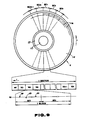
- an annular label section 2 is provided about a central hole 1, as in the conventional disk d shown in Fig. 9, and an annular recording surface section 4 is provided around the label section 2.
- a spirally extending recording track TK forming a pattern of a large number of circular or substantially concentric turns surrounding the central hole 1.
- a plurality of registering sectors among the circular tracks, such as the sectors SC1 of the tracks, are aligned in the radial direction of the optical disk D.
- n 43, as an example.
- a plurality of registering blocks among the sectors such as the block BL1 among the sectors SC1, SC2, ... SC m , are aligned in the radial direction of this optical disk d .
- Each of the blocks BL1 BL2, ... , BL n of each of the sectors SC1, SC2, ... SC m is provided towards its incipient end with a control recording area AR C , followed by an information writing area AR D to constitute a unit information division.
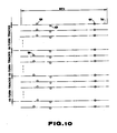
- the control recording region AR C of each of the blocks BL1, BL2, ... , BL n is divided into a servo region AR S and a traverse region AR T .
- a pair of tracking information pits Q A and Q C are provided with a shift towards the outside and the inside on both sides of a track center line K C with a spacing of a predetermined interval along the track direction, while a clock information pit Q B is provided on the track center line K C at a position intermediate between the tracking information pits Q A and Q C .
- a pair of traverse information pits Q D , Q E are provided at an interval from each other of a distance P allotted for each recording track with the clock information pit Q B as the reference.
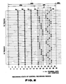
- each control recording region AR C has a data recording capacity of 30 channel bits.
- the 7th and 11th channel bits are allocated as the recording positions of the tracking information pits Q A and Q C and the 11th channel bit is allocated as the recording position of the clock information pit Q B , while the 19th and the 27th channel bits are allocated as the recording regions of the traverse information pits Q D and Q E .
- the tracking information pits Q A and Q C and the clock information pits Q B are arrayed on respective straight line along the radial direction, whereas the traverse information pits Q D are shifted in their positions in the track direction by one channel bit at intervals of four consecutive tracks, whereas the other traverse information pits Q E are shifted in their positions by one channel bit for each track, except the portions where the traverse information pits Q D are being changed in their positions at intervals of four consecutive tracks, such that the bit pattern differs on the track-by-track basis with the 16 consecutive tracks as a recurrent unit.
- the clock information pits Q B are placed intermediate between the tracking information pits Q A and Q C , the deviating scanning of the light beam for reading out the information may be facilitated.
- the relative distance P between the traverse information pits Q D and Q E provided in the traverse region AR T is changed by one channel bit between adjacent tracks, and one of the paired traverse information pits Q D and Q E is at the same position, so that the read-out errors at the time of reading out the traverse information by the traverse information pits Q D and Q E may be identified easily, such that the bit patterns of the paired traverse information pits Q D and Q E may be read out on the basis of the reproducing clocks obtained from the above clock information pits Q B under the stable tracking control on the basis of the above tracking information pits Q B .
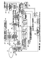
- optical disk D is employed as the disk-shaped recording medium for the disk apparatus arranged as shown for example in Fig. 3.
- a system controller 21 is responsive to the control instructions supplied from a host computer 23 connected via an interfacing circuit 22 to control the operation of the apparatus in its entirety.
- it supplies to an up/down counter 25 preset data indicating the number of the tracks up to a target track for performing a seeking control of an optical head 24 adapted for recording/reproducing the information on the optical cisk D, while supplying to a latch circuit 26 the bit pattern data of the aforementioned traverse information pits Q D , Q E previously recorded on the tracks to be erased or recorded, and also supplying erasure or recording instruction signals to a record data demodulating circuit 27 and to a laser ariving circuit 28.
- the modulating circuit 27 supplies erasure pulses to the laser drive circuit 28 at the timing conforming to the reference channel clocks CCK.
- the circuit 27 subjects the recording data written from the host computer 23 via interfacing circuit 22 into a memory 29 to a predetermined modulation, such as EFM (eight-fourteen modulation) to supply the modulated recording data pulses timed with the above channel clocks CCK to the laser driving circuit 28.
- This laser driving circuit 28 drives a laser diode, not shown, enclosed in the optical head 24, by drive pulse signals conforming to recording data pulses during the record mode operation or erasure pulses during the erasure mode operation.
- the circuit 28 supplies to the laser diode the high frequency signals adapted for high frequency driving the laser diode with a lower light volume for reproducing the information for the optical disk D.
- optical disk D is rotated accurately by a disk motor 30 at a constant angular velocity.
- the optical head 24 has enclosed therein a laser diode driven by the laser drive circuit 28 to output a laser light for information recording and or reproduction, a photodetector for detecting the laser light irradiated on the disk D and reflected thereby, and the like, such that the photo-detector output, that is, the reproducing output, is supplied to a clock reproducing circuit 32, a tracking error detecting circuit and to a pattern detecting circuit 34, while being simultaneously supplied to a demodulating circuit for data reproduction, not shown.
- This optical head 24 is moved on the radius of the optical disk D by a slide motor 35, the driving speed of which is detected by a speed sensor 36.
- a motor driving circuit 40 is servo controlled by a slide servo circuit 39 on the basis of the speed detection signals sensed by the speed sensor 36 and the target speed signal converted by a digital to analog (D/A) converter 38 from the target speed data read out from a speed information reference memory 37 with the count output by the up/down counter 55 as the address.
- D/A digital to analog
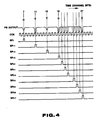
- the clock regenerating circuit 32 performs clock reproduction by a so-called phase locked loop (PLL), on the basis of the reproducing output by the clock information pits Q B in the reproducing output supplied from the optical head 24 via the preamplifier 31, for regenerating channel clocks CCK as shown in Fig. 4 and for various sampling pulses SP7, SP11, SP15, SP19, SP20, SP21, SP22, SP24, SP25, SP26 or SP27 timed to the channel clocks CCK.
- PLL phase locked loop
- the tracking error detecting circuit 33 detects the tracking error, on the basis of by the tracking information pits Q A , Q C in the reproducing output supplied from the optical head 24 via the preamplifier 31, for supplying the tracking error signals to a tracking servo circuit 41.
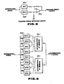
- the tracking error detecting circuit 33 is constituted by, for example, two sample-and-hold circuits 33A, 33B a differential amplifier 33C, etc., as shown in Fig. 5, and operates in such a manner that the reproducing output for the tracking information pits Q A , Q C in the reproducing output is sampled and held by the sample-and-hold circuits 33A, 33B and the level difference in the sample-held output is detected by the differential amplifier 33C as the tracking error.
- the sample pulses SP7, SP15 formed in the clock regenerating circuit 33 are used for sampling and holding of the reproducing output for the tracking information pits Q A , Q C by the sample-and-hold circuit 33A, 33B.
- the pattern discriminating circuit 34 discriminates the bit pattern of the traverse information pits Q D , Q E and supplies the discrimination output data to a latch circuit 42, a reference memory 43 for the traverse information and to a comparator 44.
- the pattern discriminating circuit 34 is constituted by the eight sample-and-hold circuits 34A, 34B to 34H and two minimum value discriminating circuits 34I, 34J.
- the aforementioned eight sample-and-hold circuits 34A and 34B-34H sample and hold the reproducing output for the traverse region AR T of the optical disk D, using the sampling pulses SP15, SP19, SP20, SP21, SP22, SP24, SP25, SP26 and SP27 formed in the clock regenerating circuit 32.
- the minimum value discriminating circuits 34I, 34J perform level comparison of the sample-held outputs by the sample-and-hold circuits 34I, 34J to form discrimination data indicating the bit pattern of the traverse information pits Q D , Q E , based on the bit timing of the sample-held reproducing outputs for the paired traverse information pits Q D , Q E contained in the reproducing output from the aforementioned traverse region AR T , that is, the sample-held outputs affording a minimum value.
- the reference memory 43 for the traverse information there are stored the data concerning the number of tracks and the changing direction based on the trackwise bit patterns of the traverse information pits Q D , Q E provided in the traverse region AR T of the optical disk D. From the reference memory 43, there are read out data indicating the number of track jumps and the direction of track jumps by the movement of the optical head 24, using the bit pattern data, before one servo block or before one track, that are given by the contents of the latch circuit 42 latching the discrimination output data obtained at the pattern discriminating circuit 34 and the bit pattern data given by the current discrimination output data obtained at the pattern discriminating circuit 34.
- the data indicating the track jump direction are supplied from the reference memory 43 to the up/down control input of the up/down counter 25 as the count control signals.
- the data indicating the number of track jumps are supplied from the reference memory 43 to a pulse producing circuit 45 where they are converted into clock pulses having a pulse number conforming to the number of track jumps, which clock pulses are then supplied to the clock input terminal of the up/down counter 25.
- the up/down counter 25 in which are preset the data indicating the number of tracks up to the target track afforded by the system controller 21, counts up or counts down the clock pulses having a pulse number conforming to the number of track jumps by the shifting of the optical head 24, to apply to the speed information reference memory 37 the count output indicating the distance to the target track as the address data.
- the target speed data read out from the reference memory 37 are converted in the digital to analog D/A) converter 38 into analog target speed signals which are then supplied to the slide servo circuit 39 to control the slide motor 35 to access the optical head 24.
- the count value of the up/down couner 25 is reset to zero.
- the comparator 44 compares the bit pattern data applied by the system controller 21 to the latch circuit 26 and the bit pattern data obtained as the discriminating output of the pattern discriminating circuit 34 and, when the two bit pattern data coincide with each other, outputs a coincidence signal having a logical value "0".
- the output of the comparator 34 is stored for each servo block by two cascaded latch circuits 46, 47 and a logical AND is taken at a first AND gate 48, the output of which is supplied to a second AND gate 49.
- the second AND gate 49 is supplied with a signal via two cascaded latch circuits 50 and 51 adapted to store erasure instruction signals or recording command signals outputted by the system controller 21 for each servo block.
- the gate 49 When the logical AND output by the first AND gate 48 indicating that non-coincidence of the pattern data has been detected for two consecutive servo-blocks during the erasure mode operation indicated by the erasure instruction signal or the recording command signal indicated by the recording command signal is supplied to the gate 49, it supplies an interrupt signal to the system controller 21.
- the system controller 21 When supplied from the second AND gate 49 with the interrupt signal, the system controller 21 cancels the erasure mode operation or the recording mode operation. When in the recording operation mode, the system controller searches for a substitution sector in the information writing region AR D of the optical disk D to restart the recording operation for this sector.
- the operation is cancelled when the deviation from the target track occurs for two consecutive servo blocks in the era sure or record operation modes.
- the operation may be cancelled when there is detected the non-coincidence of the bit pattern data of the traverse information pits extending over three or more blocks.
- the optical disk D2 in the embodiment shown in Fig.7 is provided with an annular label section 2 about the central hole 1, similarly to the optical disk D of the embodiment of Fig. 1, and an annular recording surface section 4 is provided for extending around this label section 2.
- this recording surface section 4 there is provided a spirally extending recording track TK forming a pattern of a large number of circular or substantially concentric turns surrounding the central hole 1.
- Each turn or each circular track is divided into a predetermined number m of sectors SC1 SC2, ... SC m , and a plurality of registering on corresponding sectors among the circular tracks are aligned in the radial direction.
- SC m is provided towards its incipient side with an address information section AD followed by a predetermined number n of blocks BL1, BL2, ... , BL n arrayed along the recording track TK.
- a plurality of registering blocks among the sectors are similarly arrayed along the radial direction of the optical disk D.
- Each of the blocks BL1, BL2, ... , BL n of each of these sectors SC1, SC2, ... , SC n is provided towards its incipient side with a control recording region AR C followed by an information writing region AR D to constitute a with information division.
- the control recording region AR C of each of the blocks BL1, BL2 to BL n is divided into two servo regions AR S1 , AR S2 and a traverse region AR T .
- a pair of tracking information pits Q A , Q C are previously recorded as the physical changes in profile in the form of projections and recesses at the outer and inner sides of the track centerline K C and at a predetermined spacing, herein six or seven channel bits, along the track direction.
- the second servo region AR S2 of the control recording region AR C of the control recording region AR C there is previously recorded a clock information pit Q B on the track center line K C in the form of physical changes in profile by so-called embossing.
- the above traverse region AR T there are photomagnetically recorded a pair of traverse information pits Q D , Q E at a spacing P from each other which is allocated for each recording track with the clock information pit Q B as the reference.
- each control recording region AR C has a data recording capacity of 30 channel bits.
- the 4th and 5th channel bits are allocated as the recording positions for the tracking information pits Q A alternately at interval of 16 consecutive tracks, while the 11th channel bits are allocated as the recording position for the other track information pit Q C .
- the 27th channel bits are allocated as the recording position for the clock information pit Q B .
- the 15th to 23rd channel bits are allocated as the recording region for the traverse information pits Q D , Q E .
- the tracking information pits Q C and the clock information pits Q B are radially arrayed along straight lines
- the tracking information pits Q A are shifted in the track direction by one channel bit at intervals of 16 consecutive tracks
- the traverse information pits Q D among the traverse information pits Q D , Q E are shifted in the track direction by one channel bit at intervals of four consecutive tracks
- the other traverse information pits Q E are shifted by one channel bit at one track interval along the track direction except the portion at which the traverse information pits Q D are shifted at intervals of four consecutive tracks, such that the pit pattern is changed cyclically with 16 bits as one period and the pit position differs for each track.
- rough traverse information is afforded, with 16 tracks as one unit, by the above tracking information pits Q A that are shifted by one channel bit at intervals of 16 consecutive blocks in the track direction.
- the traverse information pits Q D , Q E afford the traverse information indicating each track of the 16 consecutive blocks of one period on the track-by-track basis.
Landscapes
- Engineering & Computer Science (AREA)
- Signal Processing (AREA)
- Optical Recording Or Reproduction (AREA)
- Signal Processing For Digital Recording And Reproducing (AREA)
- Optical Record Carriers And Manufacture Thereof (AREA)
Priority Applications (1)
| Application Number | Priority Date | Filing Date | Title |
|---|---|---|---|
| AT88907357T ATE101743T1 (de) | 1987-08-21 | 1988-08-19 | Plattenfoermiger aufzeichnungstraeger. |
Applications Claiming Priority (4)
| Application Number | Priority Date | Filing Date | Title |
|---|---|---|---|
| JP20754287 | 1987-08-21 | ||
| JP207542/87 | 1987-08-21 | ||
| JP322958/87 | 1987-12-22 | ||
| JP62322958A JP2653073B2 (ja) | 1987-08-21 | 1987-12-22 | ディスク状記録媒体 |
Publications (3)
| Publication Number | Publication Date |
|---|---|
| EP0436018A1 true EP0436018A1 (de) | 1991-07-10 |
| EP0436018A4 EP0436018A4 (en) | 1991-11-13 |
| EP0436018B1 EP0436018B1 (de) | 1994-02-16 |
Family
ID=26516313
Family Applications (1)
| Application Number | Title | Priority Date | Filing Date |
|---|---|---|---|
| EP88907357A Expired - Lifetime EP0436018B1 (de) | 1987-08-21 | 1988-08-19 | Plattenförmiger aufzeichnungsträger |
Country Status (6)
| Country | Link |
|---|---|
| US (1) | US4925717A (de) |
| EP (1) | EP0436018B1 (de) |
| JP (1) | JP2653073B2 (de) |
| KR (1) | KR960015205B1 (de) |
| DE (1) | DE3887906T2 (de) |
| WO (1) | WO1989001686A1 (de) |
Families Citing this family (15)
| Publication number | Priority date | Publication date | Assignee | Title |
|---|---|---|---|---|
| JPH01243253A (ja) * | 1988-03-24 | 1989-09-27 | Matsushita Electric Ind Co Ltd | 記録担体 |
| JPH02130727A (ja) * | 1988-11-10 | 1990-05-18 | Sony Corp | ディスク状記録媒体 |
| JPH02172021A (ja) * | 1988-12-26 | 1990-07-03 | Toshiba Corp | 光ディスク |
| JP2796344B2 (ja) * | 1989-04-12 | 1998-09-10 | 株式会社日立製作所 | 光学的情報記録媒体および記録再生装置 |
| JP2798982B2 (ja) * | 1989-06-29 | 1998-09-17 | 株式会社東芝 | 光ディスク装置 |
| JP2753048B2 (ja) * | 1989-06-21 | 1998-05-18 | 株式会社東芝 | 光ディスク装置 |
| US5189290A (en) * | 1989-10-14 | 1993-02-23 | Omron Corporation | Optical card processing apparatus using tracking error signals to determine proper card orientation |
| JPH03288337A (ja) * | 1990-04-04 | 1991-12-18 | Matsushita Electric Ind Co Ltd | 光ディスクドライブ装置 |
| JP2594374B2 (ja) * | 1990-05-29 | 1997-03-26 | 松下電送株式会社 | トラックカウント方法 |
| US5327408A (en) * | 1990-09-07 | 1994-07-05 | International Business Machines Corporation | Optical disk with sector servo patterns compensating for variations in pattern size and/or radial velocity |
| JP2959588B2 (ja) * | 1991-02-14 | 1999-10-06 | ソニー株式会社 | 光磁気ディスク及びそのセクタ管理情報の記録方法ならびに再生方法 |
| JP3243800B2 (ja) * | 1991-06-07 | 2002-01-07 | ソニー株式会社 | 光ディスク媒体のグレーコードの形成方法及びトラックアドレス再生装置 |
| KR950014671B1 (ko) * | 1992-12-31 | 1995-12-13 | 현대전자산업주식회사 | 광 정보기록재생장치, 매체 및 기록재생방법 |
| TWI223243B (en) * | 2002-07-25 | 2004-11-01 | Acer Labs Inc | Optical disk system which records data onto optical disk at a constant angular velocity |
| US9841931B2 (en) * | 2014-03-31 | 2017-12-12 | Vmware, Inc. | Systems and methods of disk storage allocation for virtual machines |
Citations (5)
| Publication number | Priority date | Publication date | Assignee | Title |
|---|---|---|---|---|
| EP0077644A2 (de) * | 1981-10-15 | 1983-04-27 | BURROUGHS CORPORATION (a Delaware corporation) | Optisches Speichersystem mit verbesserter Spurnachfolgesteuerung |
| EP0089263A1 (de) * | 1982-03-12 | 1983-09-21 | Thomson-Csf | Vorgeprägter beweglicher Informationsträger und optische Spurfolgeanordnung dafür |
| EP0215556A2 (de) * | 1985-07-30 | 1987-03-25 | Koninklijke Philips Electronics N.V. | Generatorkreis für Spursignal und Aufzeichnungsträger dafür |
| EP0225259A1 (de) * | 1985-11-27 | 1987-06-10 | Alcatel Thomson Gigadisc | Datenträger mit Führungsrille und seine optische Abtastungsvorrichtung mit bewertetem Zugriff |
| WO1988001785A1 (en) * | 1986-08-25 | 1988-03-10 | Sony Corporation | A disc device and a disc-like recording medium |
Family Cites Families (4)
| Publication number | Priority date | Publication date | Assignee | Title |
|---|---|---|---|---|
| NL7314267A (nl) * | 1973-10-17 | 1975-04-21 | Philips Nv | Registratiedrager waarop informatie is aangebracht in een optisch uitleesbare struktuur. |
| US4428075A (en) * | 1981-12-21 | 1984-01-24 | Burroughs Corporation | Methods of preformatting an optical disk |
| JPS58211346A (ja) * | 1982-05-31 | 1983-12-08 | Kureha Chem Ind Co Ltd | 光磁気記録デイスク |
| JP2702907B2 (ja) * | 1985-06-19 | 1998-01-26 | 株式会社日立製作所 | 情報記録媒体及びその記録再生装置 |
-
1987
- 1987-12-22 JP JP62322958A patent/JP2653073B2/ja not_active Expired - Fee Related
-
1988
- 1988-08-19 US US07/348,486 patent/US4925717A/en not_active Expired - Lifetime
- 1988-08-19 KR KR1019890700685A patent/KR960015205B1/ko not_active IP Right Cessation
- 1988-08-19 WO PCT/JP1988/000826 patent/WO1989001686A1/ja active IP Right Grant
- 1988-08-19 DE DE3887906T patent/DE3887906T2/de not_active Expired - Fee Related
- 1988-08-19 EP EP88907357A patent/EP0436018B1/de not_active Expired - Lifetime
Patent Citations (6)
| Publication number | Priority date | Publication date | Assignee | Title |
|---|---|---|---|---|
| EP0077644A2 (de) * | 1981-10-15 | 1983-04-27 | BURROUGHS CORPORATION (a Delaware corporation) | Optisches Speichersystem mit verbesserter Spurnachfolgesteuerung |
| EP0089263A1 (de) * | 1982-03-12 | 1983-09-21 | Thomson-Csf | Vorgeprägter beweglicher Informationsträger und optische Spurfolgeanordnung dafür |
| EP0215556A2 (de) * | 1985-07-30 | 1987-03-25 | Koninklijke Philips Electronics N.V. | Generatorkreis für Spursignal und Aufzeichnungsträger dafür |
| EP0225259A1 (de) * | 1985-11-27 | 1987-06-10 | Alcatel Thomson Gigadisc | Datenträger mit Führungsrille und seine optische Abtastungsvorrichtung mit bewertetem Zugriff |
| WO1988001785A1 (en) * | 1986-08-25 | 1988-03-10 | Sony Corporation | A disc device and a disc-like recording medium |
| EP0278006A1 (de) * | 1986-08-25 | 1988-08-17 | Sony Corporation | Plattenanordnung und plattenähnliches speichermedium |
Non-Patent Citations (1)
| Title |
|---|
| See also references of WO8901686A1 * |
Also Published As
| Publication number | Publication date |
|---|---|
| DE3887906D1 (de) | 1994-03-24 |
| US4925717A (en) | 1990-05-15 |
| EP0436018B1 (de) | 1994-02-16 |
| JPH01138621A (ja) | 1989-05-31 |
| JP2653073B2 (ja) | 1997-09-10 |
| WO1989001686A1 (en) | 1989-02-23 |
| KR890702188A (ko) | 1989-12-23 |
| EP0436018A4 (en) | 1991-11-13 |
| KR960015205B1 (ko) | 1996-11-01 |
| DE3887906T2 (de) | 1994-09-01 |
Similar Documents
| Publication | Publication Date | Title |
|---|---|---|
| KR910001274B1 (ko) | 광디스크장치 | |
| EP0278006B1 (de) | Plattenanordnung und plattenähnliches speichermedium | |
| EP0984435B1 (de) | Optisches Aufzeichnungsmedium und optisches Informationsaufzeichnungs/wiedergabegerät | |
| JP2799002B2 (ja) | ディスク装置 | |
| US6487147B2 (en) | Optical information recording medium and an optical information recording/reproduction device | |
| US4925717A (en) | Disk-shaped recording medium and disk apparatus | |
| EP0516125B1 (de) | Plattengerät | |
| EP0588305A2 (de) | Optisches Informationsaufzeichnungsmedium und optisches Informationsaufzeichnungs- und Wiedergabegerät | |
| EP0368585B1 (de) | Scheibenförmiger Aufzeichnungsträger und Vorrichtung zur Aufzeichnung von Daten auf den und/oder zum Auslesen von Daten vom Aufzeichnungsträger | |
| US5343453A (en) | Method for accessing desired track on disk with plurality of recording zones with head, and apparatus therefore | |
| KR19980702367A (ko) | 광 데이터 기록/재생 매체 및 기록 방법 | |
| EP0372953B1 (de) | Methode und Gerät zur Feststellung der Zugriffsgeschwindigkeit für einen Plattenspieler | |
| US5285440A (en) | Magneto-optic disk | |
| JPS63263667A (ja) | 光情報記録デイスク | |
| US6744706B2 (en) | Optical system with tracking controller | |
| JP3729467B2 (ja) | 光情報記録媒体および光学的情報記録再生装置 | |
| JPH02189769A (ja) | 情報記録再生装置 | |
| JP2693787B2 (ja) | 光デイスクおよび光デイスク装置 | |
| JPS63193331A (ja) | 光カ−ド | |
| JPS63213119A (ja) | 光デイスク | |
| JPH03230375A (ja) | 光スポット位置検出装置 | |
| JPS63213120A (ja) | 光情報記録再生装置 | |
| JPS62139130A (ja) | 光磁気デイスク装置のトラツク位置検出装置及び光磁気デイスク | |
| JPH1079130A (ja) | 光ディスク装置およびトラッキング方法 | |
| JPH06231470A (ja) | 光ディスク |
Legal Events
| Date | Code | Title | Description |
|---|---|---|---|
| PUAI | Public reference made under article 153(3) epc to a published international application that has entered the european phase |
Free format text: ORIGINAL CODE: 0009012 |
|
| 17P | Request for examination filed |
Effective date: 19890823 |
|
| AK | Designated contracting states |
Kind code of ref document: A1 Designated state(s): AT DE FR GB IT NL |
|
| A4 | Supplementary search report drawn up and despatched |
Effective date: 19910926 |
|
| AK | Designated contracting states |
Kind code of ref document: A4 Designated state(s): AT DE FR GB IT NL |
|
| 17Q | First examination report despatched |
Effective date: 19920520 |
|
| ITTA | It: last paid annual fee | ||
| GRAA | (expected) grant |
Free format text: ORIGINAL CODE: 0009210 |
|
| AK | Designated contracting states |
Kind code of ref document: B1 Designated state(s): AT DE FR GB IT NL |
|
| REF | Corresponds to: |
Ref document number: 101743 Country of ref document: AT Date of ref document: 19940315 Kind code of ref document: T |
|
| REF | Corresponds to: |
Ref document number: 3887906 Country of ref document: DE Date of ref document: 19940324 |
|
| ITF | It: translation for a ep patent filed |
Owner name: SOCIETA' ITALIANA BREVETTI S.P.A. |
|
| ET | Fr: translation filed | ||
| PLBE | No opposition filed within time limit |
Free format text: ORIGINAL CODE: 0009261 |
|
| STAA | Information on the status of an ep patent application or granted ep patent |
Free format text: STATUS: NO OPPOSITION FILED WITHIN TIME LIMIT |
|
| 26N | No opposition filed | ||
| PGFP | Annual fee paid to national office [announced via postgrant information from national office to epo] |
Ref country code: FR Payment date: 20010810 Year of fee payment: 14 |
|
| PGFP | Annual fee paid to national office [announced via postgrant information from national office to epo] |
Ref country code: DE Payment date: 20010813 Year of fee payment: 14 Ref country code: AT Payment date: 20010813 Year of fee payment: 14 |
|
| PGFP | Annual fee paid to national office [announced via postgrant information from national office to epo] |
Ref country code: GB Payment date: 20010815 Year of fee payment: 14 |
|
| PGFP | Annual fee paid to national office [announced via postgrant information from national office to epo] |
Ref country code: NL Payment date: 20010830 Year of fee payment: 14 |
|
| REG | Reference to a national code |
Ref country code: GB Ref legal event code: IF02 |
|
| PG25 | Lapsed in a contracting state [announced via postgrant information from national office to epo] |
Ref country code: GB Free format text: LAPSE BECAUSE OF NON-PAYMENT OF DUE FEES Effective date: 20020819 Ref country code: AT Free format text: LAPSE BECAUSE OF NON-PAYMENT OF DUE FEES Effective date: 20020819 |
|
| PG25 | Lapsed in a contracting state [announced via postgrant information from national office to epo] |
Ref country code: NL Free format text: LAPSE BECAUSE OF NON-PAYMENT OF DUE FEES Effective date: 20030301 Ref country code: DE Free format text: LAPSE BECAUSE OF NON-PAYMENT OF DUE FEES Effective date: 20030301 |
|
| GBPC | Gb: european patent ceased through non-payment of renewal fee |
Effective date: 20020819 |
|
| PG25 | Lapsed in a contracting state [announced via postgrant information from national office to epo] |
Ref country code: FR Free format text: LAPSE BECAUSE OF NON-PAYMENT OF DUE FEES Effective date: 20030430 |
|
| NLV4 | Nl: lapsed or anulled due to non-payment of the annual fee |
Effective date: 20030301 |
|
| REG | Reference to a national code |
Ref country code: FR Ref legal event code: ST |
|
| PG25 | Lapsed in a contracting state [announced via postgrant information from national office to epo] |
Ref country code: IT Free format text: LAPSE BECAUSE OF NON-PAYMENT OF DUE FEES;WARNING: LAPSES OF ITALIAN PATENTS WITH EFFECTIVE DATE BEFORE 2007 MAY HAVE OCCURRED AT ANY TIME BEFORE 2007. THE CORRECT EFFECTIVE DATE MAY BE DIFFERENT FROM THE ONE RECORDED. Effective date: 20050819 |