EP0435291A1 - Kombinierte Turbomolekularpumpe mit zwei Wellen und atmosphärischem Auslass - Google Patents
Kombinierte Turbomolekularpumpe mit zwei Wellen und atmosphärischem Auslass Download PDFInfo
- Publication number
- EP0435291A1 EP0435291A1 EP90125589A EP90125589A EP0435291A1 EP 0435291 A1 EP0435291 A1 EP 0435291A1 EP 90125589 A EP90125589 A EP 90125589A EP 90125589 A EP90125589 A EP 90125589A EP 0435291 A1 EP0435291 A1 EP 0435291A1
- Authority
- EP
- European Patent Office
- Prior art keywords
- zone
- stator
- axis
- axes
- pump
- Prior art date
- Legal status (The legal status is an assumption and is not a legal conclusion. Google has not performed a legal analysis and makes no representation as to the accuracy of the status listed.)
- Granted
Links
Images


Classifications
-
- F—MECHANICAL ENGINEERING; LIGHTING; HEATING; WEAPONS; BLASTING
- F04—POSITIVE - DISPLACEMENT MACHINES FOR LIQUIDS; PUMPS FOR LIQUIDS OR ELASTIC FLUIDS
- F04D—NON-POSITIVE-DISPLACEMENT PUMPS
- F04D19/00—Axial-flow pumps
- F04D19/02—Multi-stage pumps
- F04D19/04—Multi-stage pumps specially adapted to the production of a high vacuum, e.g. molecular pumps
- F04D19/046—Combinations of two or more different types of pumps
-
- F—MECHANICAL ENGINEERING; LIGHTING; HEATING; WEAPONS; BLASTING
- F04—POSITIVE - DISPLACEMENT MACHINES FOR LIQUIDS; PUMPS FOR LIQUIDS OR ELASTIC FLUIDS
- F04C—ROTARY-PISTON, OR OSCILLATING-PISTON, POSITIVE-DISPLACEMENT MACHINES FOR LIQUIDS; ROTARY-PISTON, OR OSCILLATING-PISTON, POSITIVE-DISPLACEMENT PUMPS
- F04C23/00—Combinations of two or more pumps, each being of rotary-piston or oscillating-piston type, specially adapted for elastic fluids; Pumping installations specially adapted for elastic fluids; Multi-stage pumps specially adapted for elastic fluids
- F04C23/005—Combinations of two or more pumps, each being of rotary-piston or oscillating-piston type, specially adapted for elastic fluids; Pumping installations specially adapted for elastic fluids; Multi-stage pumps specially adapted for elastic fluids of dissimilar working principle
-
- F—MECHANICAL ENGINEERING; LIGHTING; HEATING; WEAPONS; BLASTING
- F04—POSITIVE - DISPLACEMENT MACHINES FOR LIQUIDS; PUMPS FOR LIQUIDS OR ELASTIC FLUIDS
- F04D—NON-POSITIVE-DISPLACEMENT PUMPS
- F04D19/00—Axial-flow pumps
- F04D19/02—Multi-stage pumps
- F04D19/024—Multi-stage pumps with contrarotating parts
-
- F—MECHANICAL ENGINEERING; LIGHTING; HEATING; WEAPONS; BLASTING
- F04—POSITIVE - DISPLACEMENT MACHINES FOR LIQUIDS; PUMPS FOR LIQUIDS OR ELASTIC FLUIDS
- F04D—NON-POSITIVE-DISPLACEMENT PUMPS
- F04D19/00—Axial-flow pumps
- F04D19/02—Multi-stage pumps
- F04D19/04—Multi-stage pumps specially adapted to the production of a high vacuum, e.g. molecular pumps
- F04D19/042—Turbomolecular vacuum pumps
-
- F—MECHANICAL ENGINEERING; LIGHTING; HEATING; WEAPONS; BLASTING
- F04—POSITIVE - DISPLACEMENT MACHINES FOR LIQUIDS; PUMPS FOR LIQUIDS OR ELASTIC FLUIDS
- F04C—ROTARY-PISTON, OR OSCILLATING-PISTON, POSITIVE-DISPLACEMENT MACHINES FOR LIQUIDS; ROTARY-PISTON, OR OSCILLATING-PISTON, POSITIVE-DISPLACEMENT PUMPS
- F04C2240/00—Components
- F04C2240/40—Electric motor
- F04C2240/402—Plurality of electronically synchronised motors
Definitions
- a pumping unit comprising a primary pump delivering to the atmosphere and a secondary pump delivering at the suction pressure of the primary pump.
- the pressure of the enclosure, in which said process is carried out may not be as low but reach a few mbar but where it is necessary to extract, while maintaining this pressure, a certain flow of process gas, or at this pressure the primary pumps have a very low flow and therefore a pumping group is also used comprising a secondary pump and a primary pump.
- Each pump, primary and secondary has its own drive motor.
- the present invention aims to provide a unique pumping assembly and a single drive motor capable of delivering to the atmosphere and reaching very high vacuum limits up to 10 ⁇ 10 mbar.
- the subject of the invention is therefore a pump making it possible to reach a molecular vacuum, comprising a stator and a rotor assembly comprising two rotors, with parallel axes, rotating in opposite directions, the stator comprising a suction inlet and a discharge outlet , characterized in that it divides into a first zone situated on the suction side, followed by a second zone, said first zone being of the turbo-molecular type with two rotors, said second zone being of the type with two pistons rotary or screw, with two parallel axes, one of the axes being driven by a motor and the other by means of transmission means.
- each axis comprises, in the pump zone of the turbomolecular type, a series of fin discs, the distance separating the two axes corresponding approximately to the radial length of a fin plus the diameter of the hub which carries it, the discs of one axis being offset axially with respect to the discs of the other axis, the stator being provided, downstream of each rotor disc of the two rotors, of a diaphragm with stator fins, so that each diaphragm which succeeds a disc carried by one axis is in the same plane as a rotor disc carried by the other axis, said diaphragm being interrupted on a sector corresponding to the rotor space common to the two stators, located between the two axes.
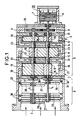
- FIG. 1 schematically represents a molecular vacuum pump according to the invention.
- FIG. 2 is a diagram illustrating the circulation of the fluid from one stage to another in the high pressure zone of the pump.
- Figure 3 is a variant of Figure 1 where the high pressure part of the pump is of another type.
- Figure 4 shows the pump of Figure 1 or 3 seen at the end from the low pressure side.
- Figure 5 shows a finned rotor disc and a finned stator diaphragm in their respective positions.
- a molecular vacuum pump which comprises a stator 1 with a suction inlet 2 and a discharge outlet 3. Inside the stator is located a rotor assembly with two rotors with two axes 4 and 5 parallel and rotating in opposite directions.
- the axis 4 is rotated by a drive motor 20 comprising a stator 6 and a rotor 7 integral with the axis 4.
- the axis 5 is rotated in opposite directions by a gear comprising two pinions 8 and 9 .
- the pump is divided into two zones: a first zone A located on the suction side and a second zone B which follows zone A.
- Zone A plays the role of secondary pump and is of the turbomolecular type and zone B plays the role of primary pump and is of the Roots type.
- zone B of the pump is of the screw type while the zone A is identical to that of FIG. 1.
- zone B of the Roots pump type, comprises three stages 10, 11, 12 separated by partitions 13, 14.
- Each Roots stage is entirely conventional and of course comprises two rotary pistons 15 and 16.
- the axes 4, 5 carry sealing labyrinths of the dynamic joint type 17.
- Bearings 18 mounted in walls end of zone B support the assembly of the two rotors.
- the suction in the first stage 10, after the discharge of the turbomolecular pump, is done by an internal conduit 19 and the discharge at the outlet of the third and last stage 12 by a conduit 21 leading to the discharge orifice 3.
- the passage from the first stage 10 to the second stage 11 and from the second stage 11 to the third stage 12 is done respectively by internal conduits 22 and 23.
- FIG. 2 is a diagram which illustrates two stages 10 and 11 of zone B.
- the synchronization gear constituted by the pinions 8, 9 is for example a dry gear. Otherwise, the gear chamber 24 is isolated from the motor 20 and the last stage 12 by seals.
- zone B is constituted by a screw pump also with three stages 10, 11, 12. Each stage, comprises two screw rotors 25 and 26, the inlet and outlet being here axial.
- Zone A is identical in the two figures 1 and 3.
- the pump is of the turbomolecular type with vanes with two rotors consisting of vanes 27 for the first rotor on axis 4 and vanes 28 for the second rotor on axis 5.
- the discs 27 and 28 are axially offset, because the distance between the two axes 4 and 5 does not allow them to be placed in the same plane. In fact, this distance corresponds to approximately the radial length of a fin of a disc more than the value of the diameter of the hub on which these fins are.
- stator 1 Downstream of each disc 27 or 28, the stator 1 is provided with a stator diaphragm, 29 on the side of the axis 4 and 30 on the side of the axis 5, these diaphragms carry fins.
- Each diaphragm 29 is located in the same plane as a disc rotor 28 and each diaphragm 30 is located in the same plane as a rotor disc 27.
- These diaphragms 29 and 30 do not form complete discs but are interrupted by the value of a sector corresponding to the rotor space common to the two stators in the part located between axes 4 and 5 as can be seen in FIG. 5.
- the ends of the fins of the diaphragms 29 and 30 are integral with a ring 31 (32 for the diaphragms 30) allowing their fixing in the stator 1 .
- a molecular pump is thus obtained capable of reaching very high secondary voids and driving back into the atmosphere, having only one drive motor and making it possible to have large flow rates in a small footprint, the flow rate being close flow which would be given by two identical pumps, but all of which would of course have a much larger volume.
Priority Applications (1)
| Application Number | Priority Date | Filing Date | Title |
|---|---|---|---|
| AT9090125589T ATE105378T1 (de) | 1989-12-28 | 1990-12-27 | Kombinierte turbomolekularpumpe mit zwei wellen und atmosphaerischem auslass. |
Applications Claiming Priority (2)
| Application Number | Priority Date | Filing Date | Title |
|---|---|---|---|
| FR8917343A FR2656658B1 (fr) | 1989-12-28 | 1989-12-28 | Pompe a vide turbomoleculaire mixte, a deux arbres de rotation et a refoulement a la pression atmospherique. |
| FR8917343 | 1989-12-28 |
Publications (2)
| Publication Number | Publication Date |
|---|---|
| EP0435291A1 true EP0435291A1 (de) | 1991-07-03 |
| EP0435291B1 EP0435291B1 (de) | 1994-05-04 |
Family
ID=9389082
Family Applications (1)
| Application Number | Title | Priority Date | Filing Date |
|---|---|---|---|
| EP90125589A Expired - Lifetime EP0435291B1 (de) | 1989-12-28 | 1990-12-27 | Kombinierte Turbomolekularpumpe mit zwei Wellen und atmosphärischem Auslass |
Country Status (8)
| Country | Link |
|---|---|
| US (1) | US5118251A (de) |
| EP (1) | EP0435291B1 (de) |
| JP (1) | JPH04209980A (de) |
| AT (1) | ATE105378T1 (de) |
| DE (1) | DE69008683T2 (de) |
| ES (1) | ES2053071T3 (de) |
| FR (1) | FR2656658B1 (de) |
| RU (1) | RU1776333C (de) |
Cited By (9)
| Publication number | Priority date | Publication date | Assignee | Title |
|---|---|---|---|---|
| EP0472933A2 (de) * | 1990-08-01 | 1992-03-04 | Matsushita Electric Industrial Co., Ltd. | Drehanlage für flüssige Medien |
| EP0585911A1 (de) * | 1992-09-03 | 1994-03-09 | Matsushita Electric Industrial Co., Ltd. | Zweistufige Trockenprimärpumpe |
| US5302089A (en) * | 1991-10-08 | 1994-04-12 | Matsushita Electric Industrial Co., Ltd. | Fluid rotating apparatus |
| US5352097A (en) * | 1992-01-23 | 1994-10-04 | Matsushita Electric Industrial Co., Ltd. | Vacuum pump |
| US5354179A (en) * | 1990-08-01 | 1994-10-11 | Matsushita Electric Industrial Co., Ltd. | Fluid rotating apparatus |
| US5449276A (en) * | 1992-01-29 | 1995-09-12 | Matsushita Electric Industrial Co., Ltd. | Two stage vacuum pump having different diameter interengaging rotors |
| US5478210A (en) * | 1992-01-31 | 1995-12-26 | Matsushita Electric Industrial Co., Ltd. | Multi-stage vacuum pump |
| EP0691475A3 (de) * | 1990-08-01 | 1997-03-26 | Matsushita Electric Ind Co Ltd | Drehkolbenanlage für flüssige Medien |
| EP0931939A3 (de) * | 1997-12-24 | 2000-08-30 | VARIAN S.p.A. | Vakuumpumpe |
Families Citing this family (26)
| Publication number | Priority date | Publication date | Assignee | Title |
|---|---|---|---|---|
| JPH05209589A (ja) * | 1992-01-31 | 1993-08-20 | Matsushita Electric Ind Co Ltd | 流体回転装置 |
| DE9202764U1 (de) * | 1992-03-02 | 1992-05-07 | Siemens Ag, 8000 Muenchen, De | |
| US5267837A (en) * | 1992-09-23 | 1993-12-07 | Mowli John C | Two-stage pumping apparatus with non-meshing first stage augers |
| DE4242406C2 (de) * | 1992-12-08 | 2002-10-31 | Grasso Gmbh Refrigeration Tech | Anordnung in einem Schraubenverdichter |
| US5363740A (en) * | 1993-07-16 | 1994-11-15 | Pneumo Abex Corporation | Fluid motor/pump with scavenged case |
| KR100346820B1 (ko) * | 1994-04-21 | 2002-11-30 | 가부시키 가이샤 에바라 세이사꾸쇼 | 다축전기모터 및 그에 결합된 용적형 진공펌프 |
| DE19930952A1 (de) * | 1999-07-05 | 2001-01-11 | Pfeiffer Vacuum Gmbh | Vakuumpumpe |
| US6508631B1 (en) | 1999-11-18 | 2003-01-21 | Mks Instruments, Inc. | Radial flow turbomolecular vacuum pump |
| DE10019066A1 (de) * | 2000-04-18 | 2001-10-25 | Leybold Vakuum Gmbh | Vakuumpumpe mit zwei zusammenwirkenden Rotoren |
| FR2807951B1 (fr) * | 2000-04-20 | 2003-05-16 | Cit Alcatel | Procede et systeme de pompage des chambres de transfert d'equipement de semi-conducteur |
| EP1234982B1 (de) * | 2001-02-22 | 2003-12-03 | VARIAN S.p.A. | Vakuumpumpe |
| KR100408153B1 (ko) * | 2001-08-14 | 2003-12-01 | 주식회사 우성진공 | 드라이 진공펌프 |
| DE10149366A1 (de) * | 2001-10-06 | 2003-04-17 | Leybold Vakuum Gmbh | Axial fördernde Reibungsvakuumpumpe |
| JP2003343469A (ja) * | 2002-03-20 | 2003-12-03 | Toyota Industries Corp | 真空ポンプ |
| US6672828B2 (en) | 2002-06-03 | 2004-01-06 | Varian S.P.A. | Vacuum pump |
| NL1022785C2 (nl) * | 2003-02-26 | 2004-08-30 | Tendris Solutions Bv | Pomp of turbine, aandrijving die een dergelijke pomp of turbine omvat en buitenboordmotor. |
| FR2854933B1 (fr) * | 2003-05-13 | 2005-08-05 | Cit Alcatel | Pompe moleculaire, turbomoleculaire ou hybride a vanne integree |
| US20050214108A1 (en) * | 2004-03-26 | 2005-09-29 | Edwin Hayes | Multi-stage dry vacuum pump for high vacuum applications |
| DE102004038677B4 (de) * | 2004-08-10 | 2016-11-24 | Pfeiffer Vacuum Gmbh | Vakuumpumpe |
| US20070020115A1 (en) * | 2005-07-01 | 2007-01-25 | The Boc Group, Inc. | Integrated pump apparatus for semiconductor processing |
| WO2007078573A2 (en) * | 2005-12-22 | 2007-07-12 | Thermo Finnigan Llc | Apparatus and method for pumping in an ion optical device |
| DE102007012408A1 (de) * | 2007-03-15 | 2008-09-18 | Aerodyn Engineering Gmbh | Windenergieanlagen mit lastübertragenden Bauteilen |
| DE102008024764A1 (de) * | 2008-05-23 | 2009-11-26 | Oerlikon Leybold Vacuum Gmbh | Mehrstufige Vakuumpumpe |
| DE202011104491U1 (de) | 2011-08-17 | 2012-11-20 | Oerlikon Leybold Vacuum Gmbh | Wälzkolbenpumpe |
| JP6616611B2 (ja) * | 2015-07-23 | 2019-12-04 | エドワーズ株式会社 | 排気システム |
| CN108252927A (zh) * | 2017-12-11 | 2018-07-06 | 安徽颐博思泵业有限责任公司 | 一种卧式多级泵 |
Citations (5)
| Publication number | Priority date | Publication date | Assignee | Title |
|---|---|---|---|---|
| GB202295A (en) * | 1922-08-12 | 1924-06-05 | Bbc Brown Boveri & Cie | Improvements in multi-stage centrifugal compressors |
| FR1397614A (fr) * | 1964-05-14 | 1965-04-30 | Neu Sa | Perfectionnement aux compresseurs |
| EP0256234A2 (de) * | 1986-06-12 | 1988-02-24 | Hitachi, Ltd. | Vakuumerzeugungssystem |
| DE3826710A1 (de) * | 1987-08-07 | 1989-02-16 | Japan Atomic Energy Res Inst | Vakuumpumpe |
| EP0340685A2 (de) * | 1988-04-30 | 1989-11-08 | Nippon Ferrofluidics Corporation | Zusammengestellte Vakuumpumpe |
Family Cites Families (7)
| Publication number | Priority date | Publication date | Assignee | Title |
|---|---|---|---|---|
| DE2833954A1 (de) * | 1978-08-03 | 1980-02-21 | Rudolf Peschke | Reibungspumpe |
| JPS61145394A (ja) * | 1984-12-18 | 1986-07-03 | Tokuda Seisakusho Ltd | 分子ポンプ |
| DE3613344A1 (de) * | 1986-04-19 | 1987-10-22 | Pfeiffer Vakuumtechnik | Turbomolekular-vakuumpumpe fuer hoeheren druck |
| JPS6375386A (ja) * | 1986-09-18 | 1988-04-05 | Mitsubishi Heavy Ind Ltd | ハイブリツド真空ポンプ |
| JPH0759956B2 (ja) * | 1986-09-19 | 1995-06-28 | 三菱重工業株式会社 | 真空ポンプ |
| JPS63147989A (ja) * | 1986-12-09 | 1988-06-20 | Daikin Ind Ltd | 複合真空ポンプ |
| JPH07111195B2 (ja) * | 1986-12-09 | 1995-11-29 | ダイキン工業株式会社 | 複合真空ポンプ |
-
1989
- 1989-12-28 FR FR8917343A patent/FR2656658B1/fr not_active Expired - Fee Related
-
1990
- 1990-12-25 JP JP2418241A patent/JPH04209980A/ja active Pending
- 1990-12-27 EP EP90125589A patent/EP0435291B1/de not_active Expired - Lifetime
- 1990-12-27 RU SU904894002A patent/RU1776333C/ru active
- 1990-12-27 DE DE69008683T patent/DE69008683T2/de not_active Expired - Fee Related
- 1990-12-27 ES ES90125589T patent/ES2053071T3/es not_active Expired - Lifetime
- 1990-12-27 US US07/634,623 patent/US5118251A/en not_active Expired - Fee Related
- 1990-12-27 AT AT9090125589T patent/ATE105378T1/de active
Patent Citations (5)
| Publication number | Priority date | Publication date | Assignee | Title |
|---|---|---|---|---|
| GB202295A (en) * | 1922-08-12 | 1924-06-05 | Bbc Brown Boveri & Cie | Improvements in multi-stage centrifugal compressors |
| FR1397614A (fr) * | 1964-05-14 | 1965-04-30 | Neu Sa | Perfectionnement aux compresseurs |
| EP0256234A2 (de) * | 1986-06-12 | 1988-02-24 | Hitachi, Ltd. | Vakuumerzeugungssystem |
| DE3826710A1 (de) * | 1987-08-07 | 1989-02-16 | Japan Atomic Energy Res Inst | Vakuumpumpe |
| EP0340685A2 (de) * | 1988-04-30 | 1989-11-08 | Nippon Ferrofluidics Corporation | Zusammengestellte Vakuumpumpe |
Cited By (15)
| Publication number | Priority date | Publication date | Assignee | Title |
|---|---|---|---|---|
| EP0472933A2 (de) * | 1990-08-01 | 1992-03-04 | Matsushita Electric Industrial Co., Ltd. | Drehanlage für flüssige Medien |
| EP0472933A3 (en) * | 1990-08-01 | 1992-09-16 | Matsushita Electric Industrial Co., Ltd. | Fluid rotating apparatus |
| US5197861A (en) * | 1990-08-01 | 1993-03-30 | Matsushita Electric Industrial Co., Ltd. | Fluid rotating apparatus |
| EP0691475A3 (de) * | 1990-08-01 | 1997-03-26 | Matsushita Electric Ind Co Ltd | Drehkolbenanlage für flüssige Medien |
| US5354179A (en) * | 1990-08-01 | 1994-10-11 | Matsushita Electric Industrial Co., Ltd. | Fluid rotating apparatus |
| US5302089A (en) * | 1991-10-08 | 1994-04-12 | Matsushita Electric Industrial Co., Ltd. | Fluid rotating apparatus |
| US5352097A (en) * | 1992-01-23 | 1994-10-04 | Matsushita Electric Industrial Co., Ltd. | Vacuum pump |
| US5445502A (en) * | 1992-01-23 | 1995-08-29 | Matsushita Electric Industrial Co., Ltd. | Vacuum pump having parallel kinetic pump inlet section |
| US5449276A (en) * | 1992-01-29 | 1995-09-12 | Matsushita Electric Industrial Co., Ltd. | Two stage vacuum pump having different diameter interengaging rotors |
| US5478210A (en) * | 1992-01-31 | 1995-12-26 | Matsushita Electric Industrial Co., Ltd. | Multi-stage vacuum pump |
| US5564907A (en) * | 1992-09-03 | 1996-10-15 | Matsushita Electric Industrial Co., Ltd. | Evacuating apparatus |
| EP0585911A1 (de) * | 1992-09-03 | 1994-03-09 | Matsushita Electric Industrial Co., Ltd. | Zweistufige Trockenprimärpumpe |
| US5709537A (en) * | 1992-09-03 | 1998-01-20 | Matsushita Electric Industrial Co., Ltd. | Evacuating apparatus |
| US5951266A (en) * | 1992-09-03 | 1999-09-14 | Matsushita Electric Industrial Co., Ltd. | Evacuating apparatus having interengaging rotors with threads having a decreasing pitch at the exhaust side |
| EP0931939A3 (de) * | 1997-12-24 | 2000-08-30 | VARIAN S.p.A. | Vakuumpumpe |
Also Published As
| Publication number | Publication date |
|---|---|
| ES2053071T3 (es) | 1994-07-16 |
| RU1776333C (ru) | 1992-11-15 |
| DE69008683D1 (de) | 1994-06-09 |
| EP0435291B1 (de) | 1994-05-04 |
| DE69008683T2 (de) | 1994-08-25 |
| JPH04209980A (ja) | 1992-07-31 |
| FR2656658A1 (fr) | 1991-07-05 |
| US5118251A (en) | 1992-06-02 |
| ATE105378T1 (de) | 1994-05-15 |
| FR2656658B1 (fr) | 1993-01-29 |
Similar Documents
| Publication | Publication Date | Title |
|---|---|---|
| EP0435291B1 (de) | Kombinierte Turbomolekularpumpe mit zwei Wellen und atmosphärischem Auslass | |
| JP3993666B2 (ja) | 改良真空ポンプ | |
| EP0173601B1 (de) | Ganz trockene und isolierte Vakuumpumpe mit geradliniger Bewegung zum Bekommen einer alternierenden Kompression | |
| FR2559848A1 (fr) | Machine a volutes pour comprimer un fluide | |
| FR2559847A1 (fr) | Machine a volutes pour comprimer un fluide | |
| EP3921515B1 (de) | Mehrstufiges pumpengehäuse und mehrstufige gaspumpe | |
| EP1613864A1 (de) | Motorradialverdichtereinheit | |
| FR2556054A1 (fr) | Diffuseur pour compresseur centrifuge | |
| FR2787147A1 (fr) | Pompe de regeneration a plage de fonctionnement etendue | |
| EP1510697B1 (de) | Vakuumpumpe | |
| FR2598179A1 (fr) | Dispositif de transfert d'air de refroidissement pour une turbine | |
| FR2627238A1 (fr) | Compresseur d'air ondulatoire | |
| NL8602052A (nl) | Hoogvacuumpomp. | |
| EP0457240B1 (de) | Turbomaschinenstufe mit vermindertem Strömungsverlust | |
| JP2007510853A (ja) | 多段式の摩擦真空ポンプ | |
| FR2629877A1 (fr) | Pompe moleculaire a vide | |
| FR2670539A1 (fr) | Pompe multi-etagee destinee particulierement au pompage d'un fluide multiphasique. | |
| FR2463865A1 (fr) | Compresseur centrifuge a deux etages | |
| JP2002526720A (ja) | ステータとロータを有する摩擦真空ポンプ | |
| FR3011583A1 (fr) | Trompe a jet pour depressuriser des enceintes de lubrification d'une turbomachine a injecteurs independants coaxiaux | |
| EP0143684B1 (de) | Mehrstufiger Serienverdichter | |
| FR2611818A1 (fr) | Pompe rotative a vide moleculaire du type a canal de gaede | |
| FR2601084A1 (fr) | Pompe centrifuge pour le refoulement de fluides contenant des gaz | |
| SU1707257A1 (ru) | Двухступенчатый турбомолекул рный вакуумный насос | |
| FR2711740A1 (fr) | Système d'aspiration de gaz à rotors multiples. |
Legal Events
| Date | Code | Title | Description |
|---|---|---|---|
| PUAI | Public reference made under article 153(3) epc to a published international application that has entered the european phase |
Free format text: ORIGINAL CODE: 0009012 |
|
| AK | Designated contracting states |
Kind code of ref document: A1 Designated state(s): AT BE CH DE DK ES FR GB GR IT LI LU NL SE |
|
| 17P | Request for examination filed |
Effective date: 19911230 |
|
| 17Q | First examination report despatched |
Effective date: 19930722 |
|
| GRAA | (expected) grant |
Free format text: ORIGINAL CODE: 0009210 |
|
| AK | Designated contracting states |
Kind code of ref document: B1 Designated state(s): AT BE CH DE DK ES FR GB GR IT LI LU NL SE |
|
| PG25 | Lapsed in a contracting state [announced via postgrant information from national office to epo] |
Ref country code: SE Free format text: THE PATENT HAS BEEN ANNULLED BY A DECISION OF A NATIONAL AUTHORITY Effective date: 19940504 Ref country code: GR Free format text: LAPSE BECAUSE OF FAILURE TO SUBMIT A TRANSLATION OF THE DESCRIPTION OR TO PAY THE FEE WITHIN THE PRESCRIBED TIME-LIMIT Effective date: 19940504 Ref country code: DK Effective date: 19940504 Ref country code: AT Effective date: 19940504 |
|
| REF | Corresponds to: |
Ref document number: 105378 Country of ref document: AT Date of ref document: 19940515 Kind code of ref document: T |
|
| REF | Corresponds to: |
Ref document number: 69008683 Country of ref document: DE Date of ref document: 19940609 |
|
| GBT | Gb: translation of ep patent filed (gb section 77(6)(a)/1977) |
Effective date: 19940517 |
|
| REG | Reference to a national code |
Ref country code: ES Ref legal event code: FG2A Ref document number: 2053071 Country of ref document: ES Kind code of ref document: T3 |
|
| ITF | It: translation for a ep patent filed |
Owner name: JACOBACCI CASETTA & PERANI S.P.A. |
|
| PG25 | Lapsed in a contracting state [announced via postgrant information from national office to epo] |
Ref country code: LU Free format text: LAPSE BECAUSE OF NON-PAYMENT OF DUE FEES Effective date: 19941231 Ref country code: BE Effective date: 19941231 |
|
| PGFP | Annual fee paid to national office [announced via postgrant information from national office to epo] |
Ref country code: NL Payment date: 19941231 Year of fee payment: 5 |
|
| PLBE | No opposition filed within time limit |
Free format text: ORIGINAL CODE: 0009261 |
|
| STAA | Information on the status of an ep patent application or granted ep patent |
Free format text: STATUS: NO OPPOSITION FILED WITHIN TIME LIMIT |
|
| 26N | No opposition filed | ||
| BERE | Be: lapsed |
Owner name: ALCATEL CIT Effective date: 19941231 |
|
| PGFP | Annual fee paid to national office [announced via postgrant information from national office to epo] |
Ref country code: ES Payment date: 19950906 Year of fee payment: 6 |
|
| PGFP | Annual fee paid to national office [announced via postgrant information from national office to epo] |
Ref country code: DE Payment date: 19950918 Year of fee payment: 6 |
|
| PGFP | Annual fee paid to national office [announced via postgrant information from national office to epo] |
Ref country code: FR Payment date: 19950927 Year of fee payment: 6 |
|
| PGFP | Annual fee paid to national office [announced via postgrant information from national office to epo] |
Ref country code: GB Payment date: 19951016 Year of fee payment: 6 |
|
| PGFP | Annual fee paid to national office [announced via postgrant information from national office to epo] |
Ref country code: CH Payment date: 19951231 Year of fee payment: 6 |
|
| PG25 | Lapsed in a contracting state [announced via postgrant information from national office to epo] |
Ref country code: NL Effective date: 19960701 |
|
| NLV4 | Nl: lapsed or anulled due to non-payment of the annual fee |
Effective date: 19960701 |
|
| PG25 | Lapsed in a contracting state [announced via postgrant information from national office to epo] |
Ref country code: GB Effective date: 19961227 |
|
| PG25 | Lapsed in a contracting state [announced via postgrant information from national office to epo] |
Ref country code: ES Free format text: LAPSE BECAUSE OF THE APPLICANT RENOUNCES Effective date: 19961228 |
|
| PG25 | Lapsed in a contracting state [announced via postgrant information from national office to epo] |
Ref country code: LI Effective date: 19961231 Ref country code: CH Effective date: 19961231 |
|
| REG | Reference to a national code |
Ref country code: CH Ref legal event code: PL |
|
| GBPC | Gb: european patent ceased through non-payment of renewal fee |
Effective date: 19961227 |
|
| PG25 | Lapsed in a contracting state [announced via postgrant information from national office to epo] |
Ref country code: FR Effective date: 19970829 |
|
| PG25 | Lapsed in a contracting state [announced via postgrant information from national office to epo] |
Ref country code: DE Effective date: 19970902 |
|
| REG | Reference to a national code |
Ref country code: FR Ref legal event code: ST |
|
| REG | Reference to a national code |
Ref country code: ES Ref legal event code: FD2A Effective date: 20010402 |
|
| PG25 | Lapsed in a contracting state [announced via postgrant information from national office to epo] |
Ref country code: IT Free format text: LAPSE BECAUSE OF NON-PAYMENT OF DUE FEES Effective date: 20051227 |