EP0435291A1 - Combined turbomolecular vacuum pump with two shafts and discharge at atmospheric pressure - Google Patents
Combined turbomolecular vacuum pump with two shafts and discharge at atmospheric pressure Download PDFInfo
- Publication number
- EP0435291A1 EP0435291A1 EP90125589A EP90125589A EP0435291A1 EP 0435291 A1 EP0435291 A1 EP 0435291A1 EP 90125589 A EP90125589 A EP 90125589A EP 90125589 A EP90125589 A EP 90125589A EP 0435291 A1 EP0435291 A1 EP 0435291A1
- Authority
- EP
- European Patent Office
- Prior art keywords
- zone
- stator
- axis
- axes
- pump
- Prior art date
- Legal status (The legal status is an assumption and is not a legal conclusion. Google has not performed a legal analysis and makes no representation as to the accuracy of the status listed.)
- Granted
Links
Images


Classifications
-
- F—MECHANICAL ENGINEERING; LIGHTING; HEATING; WEAPONS; BLASTING
- F04—POSITIVE - DISPLACEMENT MACHINES FOR LIQUIDS; PUMPS FOR LIQUIDS OR ELASTIC FLUIDS
- F04D—NON-POSITIVE-DISPLACEMENT PUMPS
- F04D19/00—Axial-flow pumps
- F04D19/02—Multi-stage pumps
- F04D19/04—Multi-stage pumps specially adapted to the production of a high vacuum, e.g. molecular pumps
- F04D19/046—Combinations of two or more different types of pumps
-
- F—MECHANICAL ENGINEERING; LIGHTING; HEATING; WEAPONS; BLASTING
- F04—POSITIVE - DISPLACEMENT MACHINES FOR LIQUIDS; PUMPS FOR LIQUIDS OR ELASTIC FLUIDS
- F04C—ROTARY-PISTON, OR OSCILLATING-PISTON, POSITIVE-DISPLACEMENT MACHINES FOR LIQUIDS; ROTARY-PISTON, OR OSCILLATING-PISTON, POSITIVE-DISPLACEMENT PUMPS
- F04C23/00—Combinations of two or more pumps, each being of rotary-piston or oscillating-piston type, specially adapted for elastic fluids; Pumping installations specially adapted for elastic fluids; Multi-stage pumps specially adapted for elastic fluids
- F04C23/005—Combinations of two or more pumps, each being of rotary-piston or oscillating-piston type, specially adapted for elastic fluids; Pumping installations specially adapted for elastic fluids; Multi-stage pumps specially adapted for elastic fluids of dissimilar working principle
-
- F—MECHANICAL ENGINEERING; LIGHTING; HEATING; WEAPONS; BLASTING
- F04—POSITIVE - DISPLACEMENT MACHINES FOR LIQUIDS; PUMPS FOR LIQUIDS OR ELASTIC FLUIDS
- F04D—NON-POSITIVE-DISPLACEMENT PUMPS
- F04D19/00—Axial-flow pumps
- F04D19/02—Multi-stage pumps
- F04D19/024—Multi-stage pumps with contrarotating parts
-
- F—MECHANICAL ENGINEERING; LIGHTING; HEATING; WEAPONS; BLASTING
- F04—POSITIVE - DISPLACEMENT MACHINES FOR LIQUIDS; PUMPS FOR LIQUIDS OR ELASTIC FLUIDS
- F04D—NON-POSITIVE-DISPLACEMENT PUMPS
- F04D19/00—Axial-flow pumps
- F04D19/02—Multi-stage pumps
- F04D19/04—Multi-stage pumps specially adapted to the production of a high vacuum, e.g. molecular pumps
- F04D19/042—Turbomolecular vacuum pumps
-
- F—MECHANICAL ENGINEERING; LIGHTING; HEATING; WEAPONS; BLASTING
- F04—POSITIVE - DISPLACEMENT MACHINES FOR LIQUIDS; PUMPS FOR LIQUIDS OR ELASTIC FLUIDS
- F04C—ROTARY-PISTON, OR OSCILLATING-PISTON, POSITIVE-DISPLACEMENT MACHINES FOR LIQUIDS; ROTARY-PISTON, OR OSCILLATING-PISTON, POSITIVE-DISPLACEMENT PUMPS
- F04C2240/00—Components
- F04C2240/40—Electric motor
- F04C2240/402—Plurality of electronically synchronised motors
Definitions
- a pumping unit comprising a primary pump delivering to the atmosphere and a secondary pump delivering at the suction pressure of the primary pump.
- the pressure of the enclosure, in which said process is carried out may not be as low but reach a few mbar but where it is necessary to extract, while maintaining this pressure, a certain flow of process gas, or at this pressure the primary pumps have a very low flow and therefore a pumping group is also used comprising a secondary pump and a primary pump.
- Each pump, primary and secondary has its own drive motor.
- the present invention aims to provide a unique pumping assembly and a single drive motor capable of delivering to the atmosphere and reaching very high vacuum limits up to 10 ⁇ 10 mbar.
- the subject of the invention is therefore a pump making it possible to reach a molecular vacuum, comprising a stator and a rotor assembly comprising two rotors, with parallel axes, rotating in opposite directions, the stator comprising a suction inlet and a discharge outlet , characterized in that it divides into a first zone situated on the suction side, followed by a second zone, said first zone being of the turbo-molecular type with two rotors, said second zone being of the type with two pistons rotary or screw, with two parallel axes, one of the axes being driven by a motor and the other by means of transmission means.
- each axis comprises, in the pump zone of the turbomolecular type, a series of fin discs, the distance separating the two axes corresponding approximately to the radial length of a fin plus the diameter of the hub which carries it, the discs of one axis being offset axially with respect to the discs of the other axis, the stator being provided, downstream of each rotor disc of the two rotors, of a diaphragm with stator fins, so that each diaphragm which succeeds a disc carried by one axis is in the same plane as a rotor disc carried by the other axis, said diaphragm being interrupted on a sector corresponding to the rotor space common to the two stators, located between the two axes.
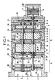
- FIG. 1 schematically represents a molecular vacuum pump according to the invention.
- FIG. 2 is a diagram illustrating the circulation of the fluid from one stage to another in the high pressure zone of the pump.
- Figure 3 is a variant of Figure 1 where the high pressure part of the pump is of another type.
- Figure 4 shows the pump of Figure 1 or 3 seen at the end from the low pressure side.
- Figure 5 shows a finned rotor disc and a finned stator diaphragm in their respective positions.
- a molecular vacuum pump which comprises a stator 1 with a suction inlet 2 and a discharge outlet 3. Inside the stator is located a rotor assembly with two rotors with two axes 4 and 5 parallel and rotating in opposite directions.
- the axis 4 is rotated by a drive motor 20 comprising a stator 6 and a rotor 7 integral with the axis 4.
- the axis 5 is rotated in opposite directions by a gear comprising two pinions 8 and 9 .
- the pump is divided into two zones: a first zone A located on the suction side and a second zone B which follows zone A.
- Zone A plays the role of secondary pump and is of the turbomolecular type and zone B plays the role of primary pump and is of the Roots type.
- zone B of the pump is of the screw type while the zone A is identical to that of FIG. 1.
- zone B of the Roots pump type, comprises three stages 10, 11, 12 separated by partitions 13, 14.
- Each Roots stage is entirely conventional and of course comprises two rotary pistons 15 and 16.
- the axes 4, 5 carry sealing labyrinths of the dynamic joint type 17.
- Bearings 18 mounted in walls end of zone B support the assembly of the two rotors.
- the suction in the first stage 10, after the discharge of the turbomolecular pump, is done by an internal conduit 19 and the discharge at the outlet of the third and last stage 12 by a conduit 21 leading to the discharge orifice 3.
- the passage from the first stage 10 to the second stage 11 and from the second stage 11 to the third stage 12 is done respectively by internal conduits 22 and 23.
- FIG. 2 is a diagram which illustrates two stages 10 and 11 of zone B.
- the synchronization gear constituted by the pinions 8, 9 is for example a dry gear. Otherwise, the gear chamber 24 is isolated from the motor 20 and the last stage 12 by seals.
- zone B is constituted by a screw pump also with three stages 10, 11, 12. Each stage, comprises two screw rotors 25 and 26, the inlet and outlet being here axial.
- Zone A is identical in the two figures 1 and 3.
- the pump is of the turbomolecular type with vanes with two rotors consisting of vanes 27 for the first rotor on axis 4 and vanes 28 for the second rotor on axis 5.
- the discs 27 and 28 are axially offset, because the distance between the two axes 4 and 5 does not allow them to be placed in the same plane. In fact, this distance corresponds to approximately the radial length of a fin of a disc more than the value of the diameter of the hub on which these fins are.
- stator 1 Downstream of each disc 27 or 28, the stator 1 is provided with a stator diaphragm, 29 on the side of the axis 4 and 30 on the side of the axis 5, these diaphragms carry fins.
- Each diaphragm 29 is located in the same plane as a disc rotor 28 and each diaphragm 30 is located in the same plane as a rotor disc 27.
- These diaphragms 29 and 30 do not form complete discs but are interrupted by the value of a sector corresponding to the rotor space common to the two stators in the part located between axes 4 and 5 as can be seen in FIG. 5.
- the ends of the fins of the diaphragms 29 and 30 are integral with a ring 31 (32 for the diaphragms 30) allowing their fixing in the stator 1 .
- a molecular pump is thus obtained capable of reaching very high secondary voids and driving back into the atmosphere, having only one drive motor and making it possible to have large flow rates in a small footprint, the flow rate being close flow which would be given by two identical pumps, but all of which would of course have a much larger volume.
Abstract
Description
Pour atteindre des vides à des pressions inférieures à 1.10⁻² mbar tout en refoulant à la pression atmosphérique, on utilise actuellement un groupe de pompage comprenant une pompe primaire refoulant à l'atmosphère et une pompe secondaire refoulant à la pression d'aspiration de la pompe primaire.
C'est également le cas de certains procédés industriels où la pression de l'enceinte, dans laquelle est effectué ledit procédé, peut n'être pas aussi basse mais atteindre quelques mbar mais où il est nécessaire d'extraire, en maintenant cette pression, un certain débit de gaz de procédé, or à cette pression les pompes primaires ont un débit très faible et on utilise donc également un groupe de pompage comprenant une pompe secondaire et une pompe primaire. Chaque pompe, primaire et secondaire, possède son propre moteur d'entraînement.To reach voids at pressures below 1.10⁻² mbar while pumping at atmospheric pressure, a pumping unit is currently used comprising a primary pump delivering to the atmosphere and a secondary pump delivering at the suction pressure of the primary pump.
This is also the case for certain industrial processes where the pressure of the enclosure, in which said process is carried out, may not be as low but reach a few mbar but where it is necessary to extract, while maintaining this pressure, a certain flow of process gas, or at this pressure the primary pumps have a very low flow and therefore a pumping group is also used comprising a secondary pump and a primary pump. Each pump, primary and secondary, has its own drive motor.
La présente invention a pour but de proposer un ensemble de pompage unique et à un seul moteur d'entraînement capable de refouler à l'atmosphère et d'atteindre à l'aspiration des vides limites très élevés jusqu'à 10⁻¹⁰ mbar.The present invention aims to provide a unique pumping assembly and a single drive motor capable of delivering to the atmosphere and reaching very high vacuum limits up to 10⁻¹⁰ mbar.
L'invention a ainsi pour objet une pompe permettant d'atteindre un vide moléculaire, comprenant un stator et un ensemble rotorique comportant deux rotors, à axes parallèles, tournant en sens inverse, le stator comportant une entrée d'aspiration et une sortie de refoulement, caractérisée en ce qu'elle se divise en une première zone située du côté de l'aspiration, suivie d'une seconde zone, ladite première zone étant du type turbo- moléculaire à deux rotors, ladite seconde zone étant du type à deux pistons rotatifs ou à vis, à deux axes parallèles, l'un des axes étant entraîné par un moteur et l'autre par l'intermédiaire de moyens de transmission.The subject of the invention is therefore a pump making it possible to reach a molecular vacuum, comprising a stator and a rotor assembly comprising two rotors, with parallel axes, rotating in opposite directions, the stator comprising a suction inlet and a discharge outlet , characterized in that it divides into a first zone situated on the suction side, followed by a second zone, said first zone being of the turbo-molecular type with two rotors, said second zone being of the type with two pistons rotary or screw, with two parallel axes, one of the axes being driven by a motor and the other by means of transmission means.
Selon une réalisation préférée de l'invention, chaque axe comporte, dans la zone à pompe du type turbomoléculaire, une suite de disques à ailettes, la distance séparant les deux axes correspondant environ à la longueur radiale d'une ailette plus le diamètre du moyeu qui la porte, les disques d'un axe étant décalés axialement par rapport aux disques de l'autre axe, le stator étant muni, en aval de chaque disque rotorique des deux rotors, d'un diaphragme à ailettes statoriques, de telle sorte que chaque diaphragme qui succède à un disque porté par un axe se trouve dans le même plan qu'un disque rotorique porté par l'autre axe, ledit diaphragme étant interrompu sur un secteur correspondant à l'espace rotorique commun aux deux stators, situé entre les deux axes.According to a preferred embodiment of the invention, each axis comprises, in the pump zone of the turbomolecular type, a series of fin discs, the distance separating the two axes corresponding approximately to the radial length of a fin plus the diameter of the hub which carries it, the discs of one axis being offset axially with respect to the discs of the other axis, the stator being provided, downstream of each rotor disc of the two rotors, of a diaphragm with stator fins, so that each diaphragm which succeeds a disc carried by one axis is in the same plane as a rotor disc carried by the other axis, said diaphragm being interrupted on a sector corresponding to the rotor space common to the two stators, located between the two axes.
On va maintenant donner la description d'un exemple de mise en oeuvre de l'invention en se référant au dessin annexé dans lequel :We will now give the description of an example of implementation of the invention with reference to the appended drawing in which:
La figure 1 représente schématiquement une pompe à vide moléculaire selon l'invention.FIG. 1 schematically represents a molecular vacuum pump according to the invention.
La figure 2 est un schéma illustrant la circulation du fluide d'un étage à l'autre dans la zone haute pression de la pompe.FIG. 2 is a diagram illustrating the circulation of the fluid from one stage to another in the high pressure zone of the pump.
La figure 3 est une variante de la figure 1 où la partie haute pression de la pompe est d'un autre type.Figure 3 is a variant of Figure 1 where the high pressure part of the pump is of another type.
La figure 4 montre la pompe de la figure 1 ou 3 vue en bout du côté basse pression.Figure 4 shows the pump of Figure 1 or 3 seen at the end from the low pressure side.
La figure 5 représente un disque rotorique à ailettes et un diaphragme statorique à ailettes dans leur position respective.Figure 5 shows a finned rotor disc and a finned stator diaphragm in their respective positions.
En se référant à la figure 1, on voit une pompe à vide moléculaire qui comprend un stator 1 avec une entrée d'aspiration 2 et une sortie de refoulement 3. A l'intérieur du stator est situé un ensemble rotorique à deux rotors à deux axes 4 et 5 parallèles et tournant en sens inverse. L'axe 4 est entraîné en rotation par un moteur d'entraînement 20 comprenant un stator 6 et un rotor 7 solidaire de l'axe 4. L'axe 5 est entraîné en rotation en sens inverse par un engrenage comportant deux pignons 8 et 9.Referring to Figure 1, there is shown a molecular vacuum pump which comprises a
La pompe est divisée en deux zones : une première zone A située du côté de l'aspiration et une seconde zone B qui suit la zone A.The pump is divided into two zones: a first zone A located on the suction side and a second zone B which follows zone A.
La zone A joue le rôle de pompe secondaire et est du type turbomoléculaire et la zone B joue le rôle de pompe primaire et est du type Roots. Dans la réalisation représentée figure 3, la zone B de la pompe est du type à vis tandis que la zone A est identique à celle de la figure 1.Zone A plays the role of secondary pump and is of the turbomolecular type and zone B plays the role of primary pump and is of the Roots type. In the embodiment shown in FIG. 3, the zone B of the pump is of the screw type while the zone A is identical to that of FIG. 1.
Sur cette figure 1, la zone B, de type pompe Roots, comprend trois étages 10, 11, 12 séparés par des cloisons 13, 14. Chaque étage Roots est tout à fait classique et comprend bien entendu deux pistons rotatifs 15 et 16.In this FIG. 1, zone B, of the Roots pump type, comprises three
Au passage des cloisons 13, 14, ainsi qu'au passage de la cloison 40 séparant la zone A de la zone B, les axes 4, 5 portent des labyrinthes d'étanchéité du type joint dynamique 17. Des roulements 18 montés dans des parois d'extrémité de la zone B supportent l'ensemble des deux rotors.When the
L'aspiration dans le premier étage 10, après le refoulement de la pompe turbomoléculaire, se fait par un conduit interne 19 et le refoulement à la sortie du troisième et dernier étage 12 par un conduit 21 aboutissant à l'orifice de refoulement 3. Le passage du premier étage 10 au second étage 11 et du second étage 11 au troisième étage 12 se fait respectivement par des conduits internes 22 et 23.The suction in the
La figure 2 est un schéma qui illustre deux étages 10 et 11 de la zone B.FIG. 2 is a diagram which illustrates two
L'engrenage de synchronisation constitué par les pignons 8, 9 est par exemple un engrenage sec. Dans le cas contraire, la chambre d'engrenage 24 est isolée du moteur 20 et du dernier étage 12 par des joints d'étanchéité.The synchronization gear constituted by the
Dans la figure 3, la zone B est constituée par une pompe à vis également à trois étages 10, 11, 12. Chaque étage, comporte deux rotors à vis 25 et 26, l'admission et le refoulement étant ici axiaux.In FIG. 3, zone B is constituted by a screw pump also with three
La zone A est identique dans les deux figures 1 et 3.Zone A is identical in the two figures 1 and 3.
Dans cette zone A, la pompe est du type turbomoléculaire à ailettes à deux rotors constitués de disques à ailettes 27 pour le premier rotor sur l'axe 4 et de disques à ailettes 28 pour le second rotor sur l'axe 5.In this zone A, the pump is of the turbomolecular type with vanes with two rotors consisting of
Comme on le voit sur les figures 1 et 3, les disques 27 et 28 sont décalés axialement, car la distance séparant les deux axes 4 et 5 ne permet pas de les mettre dans le même plan. En effet, cette distance correspond à environ la longueur radiale d'une ailette d'un disque plus à la valeur du diamètre du moyeu sur lequel sont ces ailettes.As seen in Figures 1 and 3, the
En aval de chaque disque 27 ou 28, le stator 1 est muni d'un diaphragme statorique, 29 du côté de l'axe 4 et 30 du côté de l'axe 5, ces diaphragmes portent des ailettes.Downstream of each
Chaque diaphragme 29 est situé dans le même plan qu'un disque rotorique 28 et chaque diaphragme 30 est situé dans le même plan qu'un disque rotorique 27. Ces diaphragmes 29 et 30 ne forment pas des disques complets mais sont interrompus de la valeur d'un secteur correspondant à l'espace rotorique commun aux deux stators dans la partie située entre les axes 4 et 5 comme on le voit bien sur la figure 5. Les extrémités des ailettes des diaphragmes 29 et 30 sont solidaires d'un anneau 31 (32 pour les diaphragmes 30) permettant leur fixation dans le stator 1.Each
On obtient ainsi une pompe moléculaire capable d'atteindre des vides secondaires très élevés et refoulant à l'atmosphère, n'ayant qu'un seul moteur d'entraînement et permettant d'avoir de gros débits sous un faible encombrement, le débit étant voisin du débit qui serait donné par deux pompes identiques, mais dont l'ensemble aurait bien entendu un volume beaucoup plus vaste.A molecular pump is thus obtained capable of reaching very high secondary voids and driving back into the atmosphere, having only one drive motor and making it possible to have large flow rates in a small footprint, the flow rate being close flow which would be given by two identical pumps, but all of which would of course have a much larger volume.
Claims (2)
Priority Applications (1)
| Application Number | Priority Date | Filing Date | Title |
|---|---|---|---|
| AT9090125589T ATE105378T1 (en) | 1989-12-28 | 1990-12-27 | COMBINED TURBOMOLECULAR PUMP WITH TWO SHAFT AND ATMOSPHERIC OUTLET. |
Applications Claiming Priority (2)
| Application Number | Priority Date | Filing Date | Title |
|---|---|---|---|
| FR8917343A FR2656658B1 (en) | 1989-12-28 | 1989-12-28 | MIXED TURBOMOLECULAR VACUUM PUMP, WITH TWO ROTATION SHAFTS AND WITH ATMOSPHERIC PRESSURE DISCHARGE. |
| FR8917343 | 1989-12-28 |
Publications (2)
| Publication Number | Publication Date |
|---|---|
| EP0435291A1 true EP0435291A1 (en) | 1991-07-03 |
| EP0435291B1 EP0435291B1 (en) | 1994-05-04 |
Family
ID=9389082
Family Applications (1)
| Application Number | Title | Priority Date | Filing Date |
|---|---|---|---|
| EP90125589A Expired - Lifetime EP0435291B1 (en) | 1989-12-28 | 1990-12-27 | Combined turbomolecular vacuum pump with two shafts and discharge at atmospheric pressure |
Country Status (8)
| Country | Link |
|---|---|
| US (1) | US5118251A (en) |
| EP (1) | EP0435291B1 (en) |
| JP (1) | JPH04209980A (en) |
| AT (1) | ATE105378T1 (en) |
| DE (1) | DE69008683T2 (en) |
| ES (1) | ES2053071T3 (en) |
| FR (1) | FR2656658B1 (en) |
| RU (1) | RU1776333C (en) |
Cited By (9)
| Publication number | Priority date | Publication date | Assignee | Title |
|---|---|---|---|---|
| EP0472933A2 (en) * | 1990-08-01 | 1992-03-04 | Matsushita Electric Industrial Co., Ltd. | Fluid rotating apparatus |
| EP0585911A1 (en) * | 1992-09-03 | 1994-03-09 | Matsushita Electric Industrial Co., Ltd. | Two stage primary dry pump |
| US5302089A (en) * | 1991-10-08 | 1994-04-12 | Matsushita Electric Industrial Co., Ltd. | Fluid rotating apparatus |
| US5352097A (en) * | 1992-01-23 | 1994-10-04 | Matsushita Electric Industrial Co., Ltd. | Vacuum pump |
| US5354179A (en) * | 1990-08-01 | 1994-10-11 | Matsushita Electric Industrial Co., Ltd. | Fluid rotating apparatus |
| US5449276A (en) * | 1992-01-29 | 1995-09-12 | Matsushita Electric Industrial Co., Ltd. | Two stage vacuum pump having different diameter interengaging rotors |
| US5478210A (en) * | 1992-01-31 | 1995-12-26 | Matsushita Electric Industrial Co., Ltd. | Multi-stage vacuum pump |
| EP0691475A3 (en) * | 1990-08-01 | 1997-03-26 | Matsushita Electric Ind Co Ltd | Fluid rotating apparatus |
| EP0931939A3 (en) * | 1997-12-24 | 2000-08-30 | VARIAN S.p.A. | Vacuum pump |
Families Citing this family (26)
| Publication number | Priority date | Publication date | Assignee | Title |
|---|---|---|---|---|
| JPH05209589A (en) * | 1992-01-31 | 1993-08-20 | Matsushita Electric Ind Co Ltd | Hydraulic rotating device |
| DE9202764U1 (en) * | 1992-03-02 | 1992-05-07 | Siemens Ag, 8000 Muenchen, De | |
| US5267837A (en) * | 1992-09-23 | 1993-12-07 | Mowli John C | Two-stage pumping apparatus with non-meshing first stage augers |
| DE4242406C2 (en) * | 1992-12-08 | 2002-10-31 | Grasso Gmbh Refrigeration Tech | Arrangement in a screw compressor |
| US5363740A (en) * | 1993-07-16 | 1994-11-15 | Pneumo Abex Corporation | Fluid motor/pump with scavenged case |
| TW267271B (en) * | 1994-04-21 | 1996-01-01 | Ebara Corp | |
| DE19930952A1 (en) * | 1999-07-05 | 2001-01-11 | Pfeiffer Vacuum Gmbh | Vacuum pump |
| US6508631B1 (en) | 1999-11-18 | 2003-01-21 | Mks Instruments, Inc. | Radial flow turbomolecular vacuum pump |
| DE10019066A1 (en) * | 2000-04-18 | 2001-10-25 | Leybold Vakuum Gmbh | Vacuum pump with two cooperating rotors has drive shaft with drive pulley engaging directly with take-off hear on rotor shaft to form transmission stage |
| FR2807951B1 (en) * | 2000-04-20 | 2003-05-16 | Cit Alcatel | METHOD AND SYSTEM FOR PUMPING SEMICONDUCTOR EQUIPMENT TRANSFER CHAMBERS |
| EP1234982B1 (en) * | 2001-02-22 | 2003-12-03 | VARIAN S.p.A. | Vacuum pump |
| KR100408153B1 (en) * | 2001-08-14 | 2003-12-01 | 주식회사 우성진공 | Dry vacuum pump |
| DE10149366A1 (en) * | 2001-10-06 | 2003-04-17 | Leybold Vakuum Gmbh | Axial friction vacuum pump has two concentric rotor components with drives, rotating in opposite directions to improve relative speed of pumping structures |
| JP2003343469A (en) * | 2002-03-20 | 2003-12-03 | Toyota Industries Corp | Vacuum pump |
| US6672828B2 (en) | 2002-06-03 | 2004-01-06 | Varian S.P.A. | Vacuum pump |
| NL1022785C2 (en) * | 2003-02-26 | 2004-08-30 | Tendris Solutions Bv | Pump or turbine, drive that includes such a pump or turbine and outboard motor. |
| FR2854933B1 (en) * | 2003-05-13 | 2005-08-05 | Cit Alcatel | MOLECULAR, TURBOMOLECULAR OR HYBRID PUMP WITH INTEGRATED VALVE |
| US20050214108A1 (en) * | 2004-03-26 | 2005-09-29 | Edwin Hayes | Multi-stage dry vacuum pump for high vacuum applications |
| DE102004038677B4 (en) * | 2004-08-10 | 2016-11-24 | Pfeiffer Vacuum Gmbh | vacuum pump |
| US20070020115A1 (en) * | 2005-07-01 | 2007-01-25 | The Boc Group, Inc. | Integrated pump apparatus for semiconductor processing |
| WO2007078573A2 (en) * | 2005-12-22 | 2007-07-12 | Thermo Finnigan Llc | Apparatus and method for pumping in an ion optical device |
| DE102007012408A1 (en) * | 2007-03-15 | 2008-09-18 | Aerodyn Engineering Gmbh | Wind turbines with load-transmitting components |
| DE102008024764A1 (en) * | 2008-05-23 | 2009-11-26 | Oerlikon Leybold Vacuum Gmbh | Multi-stage vacuum pump |
| DE202011104491U1 (en) | 2011-08-17 | 2012-11-20 | Oerlikon Leybold Vacuum Gmbh | Roots |
| JP6616611B2 (en) * | 2015-07-23 | 2019-12-04 | エドワーズ株式会社 | Exhaust system |
| CN108252927A (en) * | 2017-12-11 | 2018-07-06 | 安徽颐博思泵业有限责任公司 | A kind of horizontal type multi-stage pump |
Citations (5)
| Publication number | Priority date | Publication date | Assignee | Title |
|---|---|---|---|---|
| GB202295A (en) * | 1922-08-12 | 1924-06-05 | Bbc Brown Boveri & Cie | Improvements in multi-stage centrifugal compressors |
| FR1397614A (en) * | 1964-05-14 | 1965-04-30 | Neu Sa | Improvement in compressors |
| EP0256234A2 (en) * | 1986-06-12 | 1988-02-24 | Hitachi, Ltd. | Vacuum generating system |
| DE3826710A1 (en) * | 1987-08-07 | 1989-02-16 | Japan Atomic Energy Res Inst | Vacuum pump |
| EP0340685A2 (en) * | 1988-04-30 | 1989-11-08 | Nippon Ferrofluidics Corporation | Composite vacuum pump |
Family Cites Families (7)
| Publication number | Priority date | Publication date | Assignee | Title |
|---|---|---|---|---|
| DE2833954A1 (en) * | 1978-08-03 | 1980-02-21 | Rudolf Peschke | Friction impeller pump for gas or liq. - has rotors with circumferential annular grooves in mutual engagement and connected to inlet and outlet ports in housing |
| JPS61145394A (en) * | 1984-12-18 | 1986-07-03 | Tokuda Seisakusho Ltd | Molecular pump |
| DE3613344A1 (en) * | 1986-04-19 | 1987-10-22 | Pfeiffer Vakuumtechnik | TURBOMOLECULAR VACUUM PUMP FOR HIGHER PRESSURE |
| JPS6375386A (en) * | 1986-09-18 | 1988-04-05 | Mitsubishi Heavy Ind Ltd | Hybrid vacuum pump |
| JPH0759956B2 (en) * | 1986-09-19 | 1995-06-28 | 三菱重工業株式会社 | Vacuum pump |
| JPH07111195B2 (en) * | 1986-12-09 | 1995-11-29 | ダイキン工業株式会社 | Compound vacuum pump |
| JPS63147989A (en) * | 1986-12-09 | 1988-06-20 | Daikin Ind Ltd | Combination vacuum pump |
-
1989
- 1989-12-28 FR FR8917343A patent/FR2656658B1/en not_active Expired - Fee Related
-
1990
- 1990-12-25 JP JP2418241A patent/JPH04209980A/en active Pending
- 1990-12-27 DE DE69008683T patent/DE69008683T2/en not_active Expired - Fee Related
- 1990-12-27 AT AT9090125589T patent/ATE105378T1/en active
- 1990-12-27 EP EP90125589A patent/EP0435291B1/en not_active Expired - Lifetime
- 1990-12-27 ES ES90125589T patent/ES2053071T3/en not_active Expired - Lifetime
- 1990-12-27 US US07/634,623 patent/US5118251A/en not_active Expired - Fee Related
- 1990-12-27 RU SU904894002A patent/RU1776333C/en active
Patent Citations (5)
| Publication number | Priority date | Publication date | Assignee | Title |
|---|---|---|---|---|
| GB202295A (en) * | 1922-08-12 | 1924-06-05 | Bbc Brown Boveri & Cie | Improvements in multi-stage centrifugal compressors |
| FR1397614A (en) * | 1964-05-14 | 1965-04-30 | Neu Sa | Improvement in compressors |
| EP0256234A2 (en) * | 1986-06-12 | 1988-02-24 | Hitachi, Ltd. | Vacuum generating system |
| DE3826710A1 (en) * | 1987-08-07 | 1989-02-16 | Japan Atomic Energy Res Inst | Vacuum pump |
| EP0340685A2 (en) * | 1988-04-30 | 1989-11-08 | Nippon Ferrofluidics Corporation | Composite vacuum pump |
Cited By (15)
| Publication number | Priority date | Publication date | Assignee | Title |
|---|---|---|---|---|
| EP0472933A2 (en) * | 1990-08-01 | 1992-03-04 | Matsushita Electric Industrial Co., Ltd. | Fluid rotating apparatus |
| EP0472933A3 (en) * | 1990-08-01 | 1992-09-16 | Matsushita Electric Industrial Co., Ltd. | Fluid rotating apparatus |
| US5197861A (en) * | 1990-08-01 | 1993-03-30 | Matsushita Electric Industrial Co., Ltd. | Fluid rotating apparatus |
| EP0691475A3 (en) * | 1990-08-01 | 1997-03-26 | Matsushita Electric Ind Co Ltd | Fluid rotating apparatus |
| US5354179A (en) * | 1990-08-01 | 1994-10-11 | Matsushita Electric Industrial Co., Ltd. | Fluid rotating apparatus |
| US5302089A (en) * | 1991-10-08 | 1994-04-12 | Matsushita Electric Industrial Co., Ltd. | Fluid rotating apparatus |
| US5352097A (en) * | 1992-01-23 | 1994-10-04 | Matsushita Electric Industrial Co., Ltd. | Vacuum pump |
| US5445502A (en) * | 1992-01-23 | 1995-08-29 | Matsushita Electric Industrial Co., Ltd. | Vacuum pump having parallel kinetic pump inlet section |
| US5449276A (en) * | 1992-01-29 | 1995-09-12 | Matsushita Electric Industrial Co., Ltd. | Two stage vacuum pump having different diameter interengaging rotors |
| US5478210A (en) * | 1992-01-31 | 1995-12-26 | Matsushita Electric Industrial Co., Ltd. | Multi-stage vacuum pump |
| US5564907A (en) * | 1992-09-03 | 1996-10-15 | Matsushita Electric Industrial Co., Ltd. | Evacuating apparatus |
| EP0585911A1 (en) * | 1992-09-03 | 1994-03-09 | Matsushita Electric Industrial Co., Ltd. | Two stage primary dry pump |
| US5709537A (en) * | 1992-09-03 | 1998-01-20 | Matsushita Electric Industrial Co., Ltd. | Evacuating apparatus |
| US5951266A (en) * | 1992-09-03 | 1999-09-14 | Matsushita Electric Industrial Co., Ltd. | Evacuating apparatus having interengaging rotors with threads having a decreasing pitch at the exhaust side |
| EP0931939A3 (en) * | 1997-12-24 | 2000-08-30 | VARIAN S.p.A. | Vacuum pump |
Also Published As
| Publication number | Publication date |
|---|---|
| DE69008683D1 (en) | 1994-06-09 |
| JPH04209980A (en) | 1992-07-31 |
| FR2656658A1 (en) | 1991-07-05 |
| RU1776333C (en) | 1992-11-15 |
| EP0435291B1 (en) | 1994-05-04 |
| DE69008683T2 (en) | 1994-08-25 |
| ES2053071T3 (en) | 1994-07-16 |
| US5118251A (en) | 1992-06-02 |
| ATE105378T1 (en) | 1994-05-15 |
| FR2656658B1 (en) | 1993-01-29 |
Similar Documents
| Publication | Publication Date | Title |
|---|---|---|
| EP0435291B1 (en) | Combined turbomolecular vacuum pump with two shafts and discharge at atmospheric pressure | |
| JP3993666B2 (en) | Improved vacuum pump | |
| EP0173601B1 (en) | Perfectly dry and closed vacuum pump with rectilinear movement for alternating compression | |
| FR2559847A1 (en) | VOLUME MACHINE FOR COMPRESSING A FLUID | |
| EP3921515B1 (en) | Multistage pump housing and multistage gas pump | |
| WO2004094833A1 (en) | Centrifugal motor-compressor unit | |
| FR2556054A1 (en) | DIFFUSER FOR CENTRIFUGAL COMPRESSOR | |
| FR2787147A1 (en) | REGENERATION PUMP WITH EXTENDED RANGE OF OPERATION | |
| EP1510697B1 (en) | Vacuum pump | |
| FR2598179A1 (en) | COOLING AIR TRANSFER DEVICE FOR A TURBINE | |
| FR2627238A1 (en) | WAVE AIR COMPRESSOR | |
| NL8602052A (en) | HIGH VACUUM PUMP. | |
| EP0457240B1 (en) | Turbomachinery stage with reduced secondary losses | |
| JP2007510853A (en) | Multi-stage friction vacuum pump | |
| FR2629877A1 (en) | VACUUM MOLECULAR PUMP | |
| FR2552501A1 (en) | Multistage centrifugal compressor | |
| EP0490773A1 (en) | Multistage pump especially intended for pumping a multiphase fluid | |
| FR2463865A1 (en) | TWO-STAGE CENTRIFUGAL COMPRESSOR | |
| JP2002526720A (en) | Friction vacuum pump with stator and rotor | |
| FR3011583A1 (en) | JET TRUMP FOR DEPRESSURIZING LUBRICATING ENCLOSURES OF A COAXIAL INDEPENDENT INJECTOR TURBOMACHINE | |
| EP0143684B1 (en) | Multi-stage series compressor | |
| FR2611818A1 (en) | Molecular rotary vacuum pump of the Gaëde channel type | |
| EP3891399A1 (en) | Pumping unit | |
| FR2601084A1 (en) | CENTRIFUGAL PUMP FOR DELIVERY OF GAS-CONTAINING FLUIDS | |
| SU1707257A1 (en) | Double-stage turbomolecular vacuum pump |
Legal Events
| Date | Code | Title | Description |
|---|---|---|---|
| PUAI | Public reference made under article 153(3) epc to a published international application that has entered the european phase |
Free format text: ORIGINAL CODE: 0009012 |
|
| AK | Designated contracting states |
Kind code of ref document: A1 Designated state(s): AT BE CH DE DK ES FR GB GR IT LI LU NL SE |
|
| 17P | Request for examination filed |
Effective date: 19911230 |
|
| 17Q | First examination report despatched |
Effective date: 19930722 |
|
| GRAA | (expected) grant |
Free format text: ORIGINAL CODE: 0009210 |
|
| AK | Designated contracting states |
Kind code of ref document: B1 Designated state(s): AT BE CH DE DK ES FR GB GR IT LI LU NL SE |
|
| PG25 | Lapsed in a contracting state [announced via postgrant information from national office to epo] |
Ref country code: SE Free format text: THE PATENT HAS BEEN ANNULLED BY A DECISION OF A NATIONAL AUTHORITY Effective date: 19940504 Ref country code: GR Free format text: LAPSE BECAUSE OF FAILURE TO SUBMIT A TRANSLATION OF THE DESCRIPTION OR TO PAY THE FEE WITHIN THE PRESCRIBED TIME-LIMIT Effective date: 19940504 Ref country code: DK Effective date: 19940504 Ref country code: AT Effective date: 19940504 |
|
| REF | Corresponds to: |
Ref document number: 105378 Country of ref document: AT Date of ref document: 19940515 Kind code of ref document: T |
|
| REF | Corresponds to: |
Ref document number: 69008683 Country of ref document: DE Date of ref document: 19940609 |
|
| GBT | Gb: translation of ep patent filed (gb section 77(6)(a)/1977) |
Effective date: 19940517 |
|
| REG | Reference to a national code |
Ref country code: ES Ref legal event code: FG2A Ref document number: 2053071 Country of ref document: ES Kind code of ref document: T3 |
|
| ITF | It: translation for a ep patent filed |
Owner name: JACOBACCI CASETTA & PERANI S.P.A. |
|
| PG25 | Lapsed in a contracting state [announced via postgrant information from national office to epo] |
Ref country code: LU Free format text: LAPSE BECAUSE OF NON-PAYMENT OF DUE FEES Effective date: 19941231 Ref country code: BE Effective date: 19941231 |
|
| PGFP | Annual fee paid to national office [announced via postgrant information from national office to epo] |
Ref country code: NL Payment date: 19941231 Year of fee payment: 5 |
|
| PLBE | No opposition filed within time limit |
Free format text: ORIGINAL CODE: 0009261 |
|
| STAA | Information on the status of an ep patent application or granted ep patent |
Free format text: STATUS: NO OPPOSITION FILED WITHIN TIME LIMIT |
|
| 26N | No opposition filed | ||
| BERE | Be: lapsed |
Owner name: ALCATEL CIT Effective date: 19941231 |
|
| PGFP | Annual fee paid to national office [announced via postgrant information from national office to epo] |
Ref country code: ES Payment date: 19950906 Year of fee payment: 6 |
|
| PGFP | Annual fee paid to national office [announced via postgrant information from national office to epo] |
Ref country code: DE Payment date: 19950918 Year of fee payment: 6 |
|
| PGFP | Annual fee paid to national office [announced via postgrant information from national office to epo] |
Ref country code: FR Payment date: 19950927 Year of fee payment: 6 |
|
| PGFP | Annual fee paid to national office [announced via postgrant information from national office to epo] |
Ref country code: GB Payment date: 19951016 Year of fee payment: 6 |
|
| PGFP | Annual fee paid to national office [announced via postgrant information from national office to epo] |
Ref country code: CH Payment date: 19951231 Year of fee payment: 6 |
|
| PG25 | Lapsed in a contracting state [announced via postgrant information from national office to epo] |
Ref country code: NL Effective date: 19960701 |
|
| NLV4 | Nl: lapsed or anulled due to non-payment of the annual fee |
Effective date: 19960701 |
|
| PG25 | Lapsed in a contracting state [announced via postgrant information from national office to epo] |
Ref country code: GB Effective date: 19961227 |
|
| PG25 | Lapsed in a contracting state [announced via postgrant information from national office to epo] |
Ref country code: ES Free format text: LAPSE BECAUSE OF THE APPLICANT RENOUNCES Effective date: 19961228 |
|
| PG25 | Lapsed in a contracting state [announced via postgrant information from national office to epo] |
Ref country code: LI Effective date: 19961231 Ref country code: CH Effective date: 19961231 |
|
| REG | Reference to a national code |
Ref country code: CH Ref legal event code: PL |
|
| GBPC | Gb: european patent ceased through non-payment of renewal fee |
Effective date: 19961227 |
|
| PG25 | Lapsed in a contracting state [announced via postgrant information from national office to epo] |
Ref country code: FR Effective date: 19970829 |
|
| PG25 | Lapsed in a contracting state [announced via postgrant information from national office to epo] |
Ref country code: DE Effective date: 19970902 |
|
| REG | Reference to a national code |
Ref country code: FR Ref legal event code: ST |
|
| REG | Reference to a national code |
Ref country code: ES Ref legal event code: FD2A Effective date: 20010402 |
|
| PG25 | Lapsed in a contracting state [announced via postgrant information from national office to epo] |
Ref country code: IT Free format text: LAPSE BECAUSE OF NON-PAYMENT OF DUE FEES Effective date: 20051227 |