EP0433528B1 - Regelvorrichtung mit zwei durchflussgesteuerten Ausgängen - Google Patents
Regelvorrichtung mit zwei durchflussgesteuerten Ausgängen Download PDFInfo
- Publication number
- EP0433528B1 EP0433528B1 EP90100687A EP90100687A EP0433528B1 EP 0433528 B1 EP0433528 B1 EP 0433528B1 EP 90100687 A EP90100687 A EP 90100687A EP 90100687 A EP90100687 A EP 90100687A EP 0433528 B1 EP0433528 B1 EP 0433528B1
- Authority
- EP
- European Patent Office
- Prior art keywords
- valve
- gas
- control device
- flow rate
- flow
- Prior art date
- Legal status (The legal status is an assumption and is not a legal conclusion. Google has not performed a legal analysis and makes no representation as to the accuracy of the status listed.)
- Expired - Lifetime
Links
- 238000010411 cooking Methods 0.000 claims description 2
- 230000002093 peripheral effect Effects 0.000 claims 1
- 238000002485 combustion reaction Methods 0.000 abstract 1
- 230000001105 regulatory effect Effects 0.000 description 10
- 230000001276 controlling effect Effects 0.000 description 3
Images

Classifications
-
- F—MECHANICAL ENGINEERING; LIGHTING; HEATING; WEAPONS; BLASTING
- F23—COMBUSTION APPARATUS; COMBUSTION PROCESSES
- F23N—REGULATING OR CONTROLLING COMBUSTION
- F23N5/00—Systems for controlling combustion
- F23N5/02—Systems for controlling combustion using devices responsive to thermal changes or to thermal expansion of a medium
- F23N5/10—Systems for controlling combustion using devices responsive to thermal changes or to thermal expansion of a medium using thermocouples
- F23N5/107—Systems for controlling combustion using devices responsive to thermal changes or to thermal expansion of a medium using thermocouples using mechanical means, e.g. safety valves
-
- F—MECHANICAL ENGINEERING; LIGHTING; HEATING; WEAPONS; BLASTING
- F23—COMBUSTION APPARATUS; COMBUSTION PROCESSES
- F23N—REGULATING OR CONTROLLING COMBUSTION
- F23N5/00—Systems for controlling combustion
- F23N5/02—Systems for controlling combustion using devices responsive to thermal changes or to thermal expansion of a medium
- F23N5/06—Systems for controlling combustion using devices responsive to thermal changes or to thermal expansion of a medium using bellows; using diaphragms
- F23N5/067—Systems for controlling combustion using devices responsive to thermal changes or to thermal expansion of a medium using bellows; using diaphragms using mechanical means
-
- G—PHYSICS
- G05—CONTROLLING; REGULATING
- G05D—SYSTEMS FOR CONTROLLING OR REGULATING NON-ELECTRIC VARIABLES
- G05D23/00—Control of temperature
- G05D23/01—Control of temperature without auxiliary power
- G05D23/12—Control of temperature without auxiliary power with sensing element responsive to pressure or volume changes in a confined fluid
- G05D23/125—Control of temperature without auxiliary power with sensing element responsive to pressure or volume changes in a confined fluid the sensing element being placed outside a regulating fluid flow
- G05D23/126—Control of temperature without auxiliary power with sensing element responsive to pressure or volume changes in a confined fluid the sensing element being placed outside a regulating fluid flow using a capillary tube
- G05D23/127—Control of temperature without auxiliary power with sensing element responsive to pressure or volume changes in a confined fluid the sensing element being placed outside a regulating fluid flow using a capillary tube to control a gaseous fluid circulation
- G05D23/128—Control of temperature without auxiliary power with sensing element responsive to pressure or volume changes in a confined fluid the sensing element being placed outside a regulating fluid flow using a capillary tube to control a gaseous fluid circulation the fluid being combustible
-
- F—MECHANICAL ENGINEERING; LIGHTING; HEATING; WEAPONS; BLASTING
- F23—COMBUSTION APPARATUS; COMBUSTION PROCESSES
- F23N—REGULATING OR CONTROLLING COMBUSTION
- F23N2235/00—Valves, nozzles or pumps
- F23N2235/12—Fuel valves
-
- F—MECHANICAL ENGINEERING; LIGHTING; HEATING; WEAPONS; BLASTING
- F23—COMBUSTION APPARATUS; COMBUSTION PROCESSES
- F23N—REGULATING OR CONTROLLING COMBUSTION
- F23N2235/00—Valves, nozzles or pumps
- F23N2235/12—Fuel valves
- F23N2235/18—Groups of two or more valves
-
- F—MECHANICAL ENGINEERING; LIGHTING; HEATING; WEAPONS; BLASTING
- F23—COMBUSTION APPARATUS; COMBUSTION PROCESSES
- F23N—REGULATING OR CONTROLLING COMBUSTION
- F23N2235/00—Valves, nozzles or pumps
- F23N2235/12—Fuel valves
- F23N2235/24—Valve details
-
- F—MECHANICAL ENGINEERING; LIGHTING; HEATING; WEAPONS; BLASTING
- F23—COMBUSTION APPARATUS; COMBUSTION PROCESSES
- F23N—REGULATING OR CONTROLLING COMBUSTION
- F23N5/00—Systems for controlling combustion
- F23N5/02—Systems for controlling combustion using devices responsive to thermal changes or to thermal expansion of a medium
- F23N5/10—Systems for controlling combustion using devices responsive to thermal changes or to thermal expansion of a medium using thermocouples
Definitions
- the invention relates to a control device for controlling the gas supply to a gas burner with two hob areas, which are fed via two separate gas inlets from the respectively assigned two gas outlets of the control device, with a first valve located after the gas inlet of the control device, which controls the flow and is operated by hand.
- a first valve located after the gas inlet of the control device, which controls the flow and is operated by hand.
- a second valve regulating the flow rate, the setting of which is changed by a second thermal sensor, the flow rate being adjustable by hand using the handle of the first valve.
- Such a device is known for example from US-A-2 807 423.
- thermally controlled regulating devices for controlling the gas supply are known. In all of these thermally controlled regulating devices, it is not possible to combine the flow rate of two gas outlets which are provided separately and separately from one another simultaneously via one valve actuator To determine control device, at the same time variable flow rates are possible through intermediate positions of the actuator, since in known control devices only the flow rate of a gas outlet is always controlled via a valve actuator of the control device.
- Thermally controlled regulating devices with two gas outlets which are separated independently of one another are also known, but the flow rate for the second gas outlet is only achieved by completely releasing the shut-off device.
- the object of the invention is to improve a thermally controlled control device in such a way that at least two gas outlets which are provided separately and independently of one another can be controlled in terms of flow at the same time together via a valve actuator and a single control device, variable flow settings being possible at the same time through intermediate positions of the actuator.
- This object is achieved in that the gas flows through a single line from the gas inlet to the first valve and from there to the second valve, that behind the second valve the gas flow branches to the two gas outlets and that the branched off behind the second valve to the second
- the gas outlet leading line is guided over the valve actuator of the first valve and the flow rate can be adjusted by the latter using a second control device.
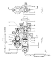
- the thermally controlled control device (first valve 2, 5, 11, 12 for controlling the gas supply to a gas consumption device I, II, in particular a gas appliance) has two shut-off devices 2, 5 arranged one behind the other in the line in the control device, one of which 5 as a thermally controlled one Shut-off device only blocks or completely releases the gas supply and the other, as a control device, determines the flow rate of two gas outlets A1, A2 which are provided separately from one another by means of intermediate positions of actuator 2.
- Valve actuators 2.5 of both shut-off devices are actuated by a common adjusting spindle 3.
- Valve actuator 5 of the shut-off device lies coaxial to the spindle axis 3 and the valve actuator 2 of the control device outside the spindle axis.
- the valve actuator 5 of the thermoelectric ignition fuse T1 is opened and thus allows a gas flow via an axially arranged bore 11 in the actuator 2, further via a first radially extending groove 12 arranged on the outermost cone of the actuator 2, which is connected to the axially arranged bore 11 of the actuator 2, further via a first existing in the housing 1 Supply bore 6 to the open valve actuator 7 of the control device T2 and further to the output A1, which is arranged on the housing 1, and can thus reach a gas inlet 1 of the hob area I shown in FIG.
- the amount of gas flowing into the distribution chamber 14 through the opened valve actuator 7 of the control device T2 is first returned via a second supply bore 10 arranged in the housing 1 until the actuator 2 is shut off.
- the amount of gas arriving through the supply bore 10 is passed through a second groove 13 radially arranged on the outer conical surface of the actuator 2 to the outlet A2 of the housing 1 passed on and can thus reach the gas inlet 2 of the hob area II shown in FIG.
- the amount of gas that now reaches the hob areas I and II through the outputs A1 and A2 of the housing 1 is regulated by the valve actuator 7 of the thermocouple control device T2 in such a way that a regulated amount of gas always exits the hob I and II in FIG and thus a desired temperature can be achieved when cooking.
- the gas quantity of the outputs A1 and A2 is increased by the valve actuator 7 of the control device T 2 and by an axial stroke movement of the control bushing 15, which via a screw gear 16 the adjusting spindle 3 is controlled so that different desired temperatures are possible on the two cooktops I and II, a maximum temperature being reached in item 2 and a minimum temperature being in item 3.
- valve actuator 7 of the control device T2 By actuating the actuator 2 via the adjusting spindle 3, there is a flow to the valve actuator 7 of the control device T2, the flow rate regulated by the valve actuator 7 of the control device T2 opening into a distribution chamber 14 inside the housing, from where in each case one supply bore exits the regulated one Flow rate to the first and second gas outlet A1 allows. While the regulated flow rate of the first gas outlet A1 leads directly to the burner, the regulated flow rate for the second gas outlet A2 is returned to the actuator 2 through a provided housing supply bore 10 and can only flow to the second gas outlet A2 in an intended switching position of the actuator 2.
Landscapes
- Engineering & Computer Science (AREA)
- Chemical & Material Sciences (AREA)
- Combustion & Propulsion (AREA)
- Mechanical Engineering (AREA)
- General Engineering & Computer Science (AREA)
- Physics & Mathematics (AREA)
- Fluid Mechanics (AREA)
- General Physics & Mathematics (AREA)
- Automation & Control Theory (AREA)
- Feeding And Controlling Fuel (AREA)
- Selective Calling Equipment (AREA)
- Preparation Of Compounds By Using Micro-Organisms (AREA)
- Massaging Devices (AREA)
- Flow Control (AREA)
Applications Claiming Priority (2)
| Application Number | Priority Date | Filing Date | Title |
|---|---|---|---|
| DE3941879 | 1989-12-19 | ||
| DE3941879A DE3941879C1 (enExample) | 1989-12-19 | 1989-12-19 |
Publications (2)
| Publication Number | Publication Date |
|---|---|
| EP0433528A1 EP0433528A1 (de) | 1991-06-26 |
| EP0433528B1 true EP0433528B1 (de) | 1995-03-15 |
Family
ID=6395783
Family Applications (1)
| Application Number | Title | Priority Date | Filing Date |
|---|---|---|---|
| EP90100687A Expired - Lifetime EP0433528B1 (de) | 1989-12-19 | 1990-01-13 | Regelvorrichtung mit zwei durchflussgesteuerten Ausgängen |
Country Status (5)
| Country | Link |
|---|---|
| EP (1) | EP0433528B1 (enExample) |
| AT (1) | ATE119987T1 (enExample) |
| DE (2) | DE3941879C1 (enExample) |
| DK (1) | DK0433528T3 (enExample) |
| ES (1) | ES2068924T3 (enExample) |
Families Citing this family (5)
| Publication number | Priority date | Publication date | Assignee | Title |
|---|---|---|---|---|
| IT1264955B1 (it) * | 1993-07-20 | 1996-10-17 | Sit La Precisa Spa | Azionatore per bruciatore a gas con sicurezza di fiamma ed elettrovalvola di regolazione. |
| DE4411906C1 (de) * | 1994-04-07 | 1995-05-18 | Elektro Gas Armaturen | Vorrichtung zur Erzeugung einer linearen Schubbewegung, insbesondere als Thermosteuerung einer Gasbrennstelle, sowie Verfahren zu deren Herstellung |
| IT1272322B (it) * | 1994-07-08 | 1997-06-16 | Balestra Micromecc Libero | "dispositivo adattatore per la modifica della applicazione di termocoppie da innesto filettato a innesto tipo faston su gruppi magnetici standard di valvole o rubinetti valvolati per gas" |
| DE9413047U1 (de) | 1994-08-12 | 1994-11-03 | Elektro- Und Gas-Armaturen-Fabrik Gmbh, 58119 Hagen | Vorrichtung zur Regelung von Steuervorgängen, insbesondere als Thermosteuerung einer Gasbrennstelle |
| GB2469091A (en) * | 2009-04-01 | 2010-10-06 | Diamond H Controls Ltd | Thermostatic control device for gas appliances |
Family Cites Families (8)
| Publication number | Priority date | Publication date | Assignee | Title |
|---|---|---|---|---|
| DE647300C (de) * | 1936-05-13 | 1937-07-01 | Junkers & Co | Mehrwege-Sicherheits-Gashahn |
| US2807423A (en) * | 1955-01-19 | 1957-09-24 | Dole Valve Co | Gas oven thermostatic valve |
| US3146945A (en) * | 1962-02-27 | 1964-09-01 | Robertshaw Controls Co | Thermostatic control for range burners |
| DE1529095A1 (de) * | 1964-11-09 | 1969-12-04 | Robertshaw Controls Co | Thermostatisch gesteuerter Brennmittelregler |
| US3288366A (en) * | 1964-12-23 | 1966-11-29 | Aurora Corp | Thermostatic gas regulator for baking and broiling |
| NL6613224A (enExample) * | 1966-09-20 | 1968-03-21 | ||
| DE2556982C3 (de) * | 1975-12-18 | 1979-03-08 | Fa. Otto Egelhof, 7012 Fellbach | Temperaturregler für gasbeheizte Geräte |
| DE8902031U1 (de) * | 1989-02-21 | 1989-05-03 | VARA S.n.c. di Pintossi Angelo e Pintossi Franco, Lumezzane S. Sebastiano | Thermostatisch gesteuerte Hahnvorrichtung insbesondere, zur Anwendung in Öfen und Herden zum Kochen und Backen von Speisen |
-
1989
- 1989-12-19 DE DE3941879A patent/DE3941879C1/de not_active Expired - Fee Related
-
1990
- 1990-01-13 ES ES90100687T patent/ES2068924T3/es not_active Expired - Lifetime
- 1990-01-13 AT AT90100687T patent/ATE119987T1/de not_active IP Right Cessation
- 1990-01-13 DE DE59008714T patent/DE59008714D1/de not_active Expired - Fee Related
- 1990-01-13 DK DK90100687.4T patent/DK0433528T3/da active
- 1990-01-13 EP EP90100687A patent/EP0433528B1/de not_active Expired - Lifetime
Also Published As
| Publication number | Publication date |
|---|---|
| EP0433528A1 (de) | 1991-06-26 |
| DK0433528T3 (da) | 1995-07-24 |
| ATE119987T1 (de) | 1995-04-15 |
| DE3941879C1 (enExample) | 1991-06-13 |
| ES2068924T3 (es) | 1995-05-01 |
| DE59008714D1 (de) | 1995-04-20 |
Similar Documents
| Publication | Publication Date | Title |
|---|---|---|
| EP0818655B1 (de) | Verfahren und Vorrichtung zum Steuern der Flammengrösse gasbetriebener Koch- oder Backgeräte | |
| DE2343861C2 (de) | Brenner für Öfen der Metallverarbeitung | |
| EP1130177A2 (de) | Wasserauslaufventilanordnung | |
| EP0356621A1 (de) | Dreiwege-Ventil | |
| EP0433528B1 (de) | Regelvorrichtung mit zwei durchflussgesteuerten Ausgängen | |
| DE2941543C2 (de) | Vorrichtung zur Steuerung der Gaszufuhr | |
| WO1991008532A1 (de) | Sanitäre mischbatterie | |
| EP2993402B1 (de) | Gasventileinrichtung für ein gasgerät und gasgerät | |
| DE2312305C2 (de) | Einrichtung zum Beeinflussen der Leistung eines gasbeheizten Durchlauf-Wassererhitzers | |
| DE944225C (de) | Temperaturregler fuer Gasbackoefen, Gasheizungen u. dgl. | |
| DE3223108A1 (de) | Oelbrenneranordnung fuer feldkochherde | |
| EP2846094A2 (de) | Gasventileinrichtung und Gasgerät mit einer Gasventileinrichtung | |
| DE3544583A1 (de) | Drehschalter fuer gasherde | |
| DE60005851T2 (de) | Eine ventileinheit zur regelung der gasdurchflussmenge in abhängkeit der wasserdurchflussmenge, insbesondere für wassererhitzer | |
| DE102020102434A1 (de) | Mischwasserarmatur mit kompaktem Thermostatventil | |
| EP0926437A1 (de) | Gasbrenneranordnung für Kochstellen | |
| EP1353126B1 (de) | Hydraulisch geregelte Gasarmatur | |
| DE10322217A1 (de) | Einstelleinrichtung für ein Gaskochgerät und Gaskochgerät | |
| DE19534909A1 (de) | Gerät zum Erwärmen von Heizungswasser und Bereiten von Brauchwasser | |
| DE19920112B4 (de) | Brenner | |
| DE1429094C (de) | Sicherheitsventil | |
| DE2748743C2 (de) | Gasheizgerät | |
| DE2659456A1 (de) | Gasbeheizter durchlauf-wassererhitzer | |
| DE19533729A1 (de) | Gerät zum Erwärmen von Heizungswasser und Bereiten von Brauchwasser | |
| DE3445476A1 (de) | Druckgesteuertes mischventil |
Legal Events
| Date | Code | Title | Description |
|---|---|---|---|
| PUAI | Public reference made under article 153(3) epc to a published international application that has entered the european phase |
Free format text: ORIGINAL CODE: 0009012 |
|
| 17P | Request for examination filed |
Effective date: 19910429 |
|
| AK | Designated contracting states |
Kind code of ref document: A1 Designated state(s): AT BE CH DE DK ES FR GB GR IT LI LU NL SE |
|
| 17Q | First examination report despatched |
Effective date: 19921029 |
|
| GRAA | (expected) grant |
Free format text: ORIGINAL CODE: 0009210 |
|
| AK | Designated contracting states |
Kind code of ref document: B1 Designated state(s): AT BE CH DE DK ES FR GB GR IT LI LU NL SE |
|
| PG25 | Lapsed in a contracting state [announced via postgrant information from national office to epo] |
Ref country code: GR Free format text: LAPSE BECAUSE OF FAILURE TO SUBMIT A TRANSLATION OF THE DESCRIPTION OR TO PAY THE FEE WITHIN THE PRESCRIBED TIME-LIMIT Effective date: 19950315 |
|
| REF | Corresponds to: |
Ref document number: 119987 Country of ref document: AT Date of ref document: 19950415 Kind code of ref document: T |
|
| REF | Corresponds to: |
Ref document number: 59008714 Country of ref document: DE Date of ref document: 19950420 |
|
| REG | Reference to a national code |
Ref country code: ES Ref legal event code: FG2A Ref document number: 2068924 Country of ref document: ES Kind code of ref document: T3 |
|
| ITF | It: translation for a ep patent filed | ||
| GBT | Gb: translation of ep patent filed (gb section 77(6)(a)/1977) |
Effective date: 19950419 |
|
| ET | Fr: translation filed | ||
| PG25 | Lapsed in a contracting state [announced via postgrant information from national office to epo] |
Ref country code: SE Effective date: 19950615 |
|
| REG | Reference to a national code |
Ref country code: DK Ref legal event code: T3 |
|
| PG25 | Lapsed in a contracting state [announced via postgrant information from national office to epo] |
Ref country code: GB Effective date: 19960113 Ref country code: DK Effective date: 19960113 Ref country code: AT Effective date: 19960113 |
|
| REG | Reference to a national code |
Ref country code: DK Ref legal event code: EBP |
|
| PG25 | Lapsed in a contracting state [announced via postgrant information from national office to epo] |
Ref country code: ES Free format text: LAPSE BECAUSE OF NON-PAYMENT OF DUE FEES Effective date: 19960115 |
|
| PLBE | No opposition filed within time limit |
Free format text: ORIGINAL CODE: 0009261 |
|
| STAA | Information on the status of an ep patent application or granted ep patent |
Free format text: STATUS: NO OPPOSITION FILED WITHIN TIME LIMIT |
|
| PG25 | Lapsed in a contracting state [announced via postgrant information from national office to epo] |
Ref country code: LU Free format text: LAPSE BECAUSE OF NON-PAYMENT OF DUE FEES Effective date: 19960131 Ref country code: LI Effective date: 19960131 Ref country code: CH Effective date: 19960131 Ref country code: BE Effective date: 19960131 |
|
| 26N | No opposition filed | ||
| BERE | Be: lapsed |
Owner name: PAUL ISPHORDING METALLWERKE G.M.B.H. & CO. K.G. Effective date: 19960131 |
|
| PG25 | Lapsed in a contracting state [announced via postgrant information from national office to epo] |
Ref country code: NL Effective date: 19960801 |
|
| GBPC | Gb: european patent ceased through non-payment of renewal fee |
Effective date: 19960113 |
|
| REG | Reference to a national code |
Ref country code: CH Ref legal event code: PL |
|
| PG25 | Lapsed in a contracting state [announced via postgrant information from national office to epo] |
Ref country code: FR Effective date: 19960930 |
|
| NLV4 | Nl: lapsed or anulled due to non-payment of the annual fee |
Effective date: 19960801 |
|
| PG25 | Lapsed in a contracting state [announced via postgrant information from national office to epo] |
Ref country code: DE Effective date: 19961001 |
|
| REG | Reference to a national code |
Ref country code: FR Ref legal event code: ST |
|
| REG | Reference to a national code |
Ref country code: ES Ref legal event code: FD2A Effective date: 19990301 |
|
| PG25 | Lapsed in a contracting state [announced via postgrant information from national office to epo] |
Ref country code: IT Free format text: LAPSE BECAUSE OF NON-PAYMENT OF DUE FEES;WARNING: LAPSES OF ITALIAN PATENTS WITH EFFECTIVE DATE BEFORE 2007 MAY HAVE OCCURRED AT ANY TIME BEFORE 2007. THE CORRECT EFFECTIVE DATE MAY BE DIFFERENT FROM THE ONE RECORDED. Effective date: 20050113 |