EP0433528B1 - Control device with two flow controlled outlets - Google Patents
Control device with two flow controlled outlets Download PDFInfo
- Publication number
- EP0433528B1 EP0433528B1 EP90100687A EP90100687A EP0433528B1 EP 0433528 B1 EP0433528 B1 EP 0433528B1 EP 90100687 A EP90100687 A EP 90100687A EP 90100687 A EP90100687 A EP 90100687A EP 0433528 B1 EP0433528 B1 EP 0433528B1
- Authority
- EP
- European Patent Office
- Prior art keywords
- valve
- gas
- control device
- flow rate
- flow
- Prior art date
- Legal status (The legal status is an assumption and is not a legal conclusion. Google has not performed a legal analysis and makes no representation as to the accuracy of the status listed.)
- Expired - Lifetime
Links
Images

Classifications
-
- F—MECHANICAL ENGINEERING; LIGHTING; HEATING; WEAPONS; BLASTING
- F23—COMBUSTION APPARATUS; COMBUSTION PROCESSES
- F23N—REGULATING OR CONTROLLING COMBUSTION
- F23N5/00—Systems for controlling combustion
- F23N5/02—Systems for controlling combustion using devices responsive to thermal changes or to thermal expansion of a medium
- F23N5/10—Systems for controlling combustion using devices responsive to thermal changes or to thermal expansion of a medium using thermocouples
- F23N5/107—Systems for controlling combustion using devices responsive to thermal changes or to thermal expansion of a medium using thermocouples using mechanical means, e.g. safety valves
-
- F—MECHANICAL ENGINEERING; LIGHTING; HEATING; WEAPONS; BLASTING
- F23—COMBUSTION APPARATUS; COMBUSTION PROCESSES
- F23N—REGULATING OR CONTROLLING COMBUSTION
- F23N5/00—Systems for controlling combustion
- F23N5/02—Systems for controlling combustion using devices responsive to thermal changes or to thermal expansion of a medium
- F23N5/06—Systems for controlling combustion using devices responsive to thermal changes or to thermal expansion of a medium using bellows; using diaphragms
- F23N5/067—Systems for controlling combustion using devices responsive to thermal changes or to thermal expansion of a medium using bellows; using diaphragms using mechanical means
-
- G—PHYSICS
- G05—CONTROLLING; REGULATING
- G05D—SYSTEMS FOR CONTROLLING OR REGULATING NON-ELECTRIC VARIABLES
- G05D23/00—Control of temperature
- G05D23/01—Control of temperature without auxiliary power
- G05D23/12—Control of temperature without auxiliary power with sensing element responsive to pressure or volume changes in a confined fluid
- G05D23/125—Control of temperature without auxiliary power with sensing element responsive to pressure or volume changes in a confined fluid the sensing element being placed outside a regulating fluid flow
- G05D23/126—Control of temperature without auxiliary power with sensing element responsive to pressure or volume changes in a confined fluid the sensing element being placed outside a regulating fluid flow using a capillary tube
- G05D23/127—Control of temperature without auxiliary power with sensing element responsive to pressure or volume changes in a confined fluid the sensing element being placed outside a regulating fluid flow using a capillary tube to control a gaseous fluid circulation
- G05D23/128—Control of temperature without auxiliary power with sensing element responsive to pressure or volume changes in a confined fluid the sensing element being placed outside a regulating fluid flow using a capillary tube to control a gaseous fluid circulation the fluid being combustible
-
- F—MECHANICAL ENGINEERING; LIGHTING; HEATING; WEAPONS; BLASTING
- F23—COMBUSTION APPARATUS; COMBUSTION PROCESSES
- F23N—REGULATING OR CONTROLLING COMBUSTION
- F23N2235/00—Valves, nozzles or pumps
- F23N2235/12—Fuel valves
-
- F—MECHANICAL ENGINEERING; LIGHTING; HEATING; WEAPONS; BLASTING
- F23—COMBUSTION APPARATUS; COMBUSTION PROCESSES
- F23N—REGULATING OR CONTROLLING COMBUSTION
- F23N2235/00—Valves, nozzles or pumps
- F23N2235/12—Fuel valves
- F23N2235/18—Groups of two or more valves
-
- F—MECHANICAL ENGINEERING; LIGHTING; HEATING; WEAPONS; BLASTING
- F23—COMBUSTION APPARATUS; COMBUSTION PROCESSES
- F23N—REGULATING OR CONTROLLING COMBUSTION
- F23N2235/00—Valves, nozzles or pumps
- F23N2235/12—Fuel valves
- F23N2235/24—Valve details
-
- F—MECHANICAL ENGINEERING; LIGHTING; HEATING; WEAPONS; BLASTING
- F23—COMBUSTION APPARATUS; COMBUSTION PROCESSES
- F23N—REGULATING OR CONTROLLING COMBUSTION
- F23N5/00—Systems for controlling combustion
- F23N5/02—Systems for controlling combustion using devices responsive to thermal changes or to thermal expansion of a medium
- F23N5/10—Systems for controlling combustion using devices responsive to thermal changes or to thermal expansion of a medium using thermocouples
Landscapes
- Engineering & Computer Science (AREA)
- Chemical & Material Sciences (AREA)
- Combustion & Propulsion (AREA)
- Mechanical Engineering (AREA)
- General Engineering & Computer Science (AREA)
- Physics & Mathematics (AREA)
- Fluid Mechanics (AREA)
- General Physics & Mathematics (AREA)
- Automation & Control Theory (AREA)
- Feeding And Controlling Fuel (AREA)
- Massaging Devices (AREA)
- Flow Control (AREA)
- Selective Calling Equipment (AREA)
- Preparation Of Compounds By Using Micro-Organisms (AREA)
Abstract
Description
Die Erfindung betrifft eine Steuervorrichtung zum Steuern der Gaszufuhr einer Gasbrennstelle mit zwei Kochfeldbereichen, die über zwei getrennte Gaseingänge von den jeweils zugeordneten beiden Gasausgängen der Steuervorrichtung gespeist werden, mit einem nach dem Gaseingang der Steuervorrichtung liegenden, den Durchfluß steuernden und von Hand betätigten ersten Ventil, dessen Ventilstellglied durch eine thermoelektrische Zündsicherung nur öffnet, wenn eine Flamme an der Gasbrennstelle vorhanden ist, mit einem die Durchflußmenge regelnden zweiten Ventil, dessen Einstellung durch einen zweiten Thermofühler verändert wird, wobei die Durchflußmenge von Hand durch den Handgriff des ersten Ventils einstellbar ist. Eine solche Vorrichtung ist beispielsweise aus US-A- 2 807 423 bekannt.The invention relates to a control device for controlling the gas supply to a gas burner with two hob areas, which are fed via two separate gas inlets from the respectively assigned two gas outlets of the control device, with a first valve located after the gas inlet of the control device, which controls the flow and is operated by hand. whose valve actuator opens by means of a thermoelectric ignition fuse only when there is a flame at the gas burning point, with a second valve regulating the flow rate, the setting of which is changed by a second thermal sensor, the flow rate being adjustable by hand using the handle of the first valve. Such a device is known for example from US-A-2 807 423.
Es sind verschiedene thermisch gesteuerte Regelvorrichtungen zum Steuern der Gaszufuhr bekannt. Bei allen diesen thermisch gesteuerten Regelvorrichtungen ist es nicht möglich, die Durchflußmenge von zwei unabhängig voneinander getrennt vorgesehenen Gasabgängen gleichzeitig zusammen über ein Ventilstellglied mit einer einzigen Steuervorrichtung zu bestimmen, wobei gleichzeitg durch Zwischenstellungen des Stellgliedes variable Durchflußmengen möglich sind, da bei bekannten Regelvorrichtungen immer nur die Durchflußmenge eines Gasabgangs über ein Ventilstellglied der Steuervorrichtung gesteuert wird.Various thermally controlled regulating devices for controlling the gas supply are known. In all of these thermally controlled regulating devices, it is not possible to combine the flow rate of two gas outlets which are provided separately and separately from one another simultaneously via one valve actuator To determine control device, at the same time variable flow rates are possible through intermediate positions of the actuator, since in known control devices only the flow rate of a gas outlet is always controlled via a valve actuator of the control device.
Es sind auch thermisch gesteuerte Regelvorrichtungen mit zwei unabhängig voneinander getrennten Gasabgängen bekannt, wobei die Durchflußmenge für den zweiten Gasabgang jedoch nur durch vollständige Freigabe der Absperrvorrichtung erfolgt.Thermally controlled regulating devices with two gas outlets which are separated independently of one another are also known, but the flow rate for the second gas outlet is only achieved by completely releasing the shut-off device.
Aufgabe der Erfindung ist es, eine thermisch gesteuerte Regelvorrichtung derart zu verbessern, daß mindestens zwei unabhängig voneinander getrennt vorgesehene Gasabgänge gleichzeitig zusammen über ein Ventilstellglied und eine einzige Steuervorrichtung durchflußmäßig gesteuert werden können, wobei gleichzeitig durch Zwischenstellungen des Stellgliedes variable Durchflußeinstellungen möglich sind.The object of the invention is to improve a thermally controlled control device in such a way that at least two gas outlets which are provided separately and independently of one another can be controlled in terms of flow at the same time together via a valve actuator and a single control device, variable flow settings being possible at the same time through intermediate positions of the actuator.
Diese Aufgabe wird erfindungsgemäß dadurch gelöst, daß das Gas über eine einzige Leitung vom Gaseingang zum ersten Ventil und von dort zum zweiten Ventil strömt, daß hinter dem zweiten Ventil der Gasstrom zu den beiden Gasausgängen verzweigt und daß die hinter dem zweiten Ventil abgezweigte, zum zweiten Gasausgang führende Leitung über das Ventilstellglied des ersten Ventils geführt und von diesem mit einer zweiten Steuereinrichtung in der Durchflußmenge einstellbar ist.This object is achieved in that the gas flows through a single line from the gas inlet to the first valve and from there to the second valve, that behind the second valve the gas flow branches to the two gas outlets and that the branched off behind the second valve to the second The gas outlet leading line is guided over the valve actuator of the first valve and the flow rate can be adjusted by the latter using a second control device.
Eine vorteilhafte Ausgestaltung der Erfindung ist im Unteranspruch aufgeführt.An advantageous embodiment of the invention is listed in the subclaim.
Eine Ausführungsart der Erfindung wird in den schematisch dargestellten Zeichnungen gezeigt und im folgenden näher beschrieben. Es zeigen:
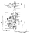
Figur 1 + 2- einen Schnitte durch die erfindungsgemäße Vorrichtung mit dargestellter Steuervorrichtung und dem Stellglied;
Figur 3- eine schematische Darstellung des Betätigungsablaufes der Regelvorrichtung;
Figur 4- eine schematische Darstellung eines Kochfeldes mit zwei Kochfeldbereichen I und II.
- Figure 1 + 2
- a section through the inventive device with the control device shown and the actuator;
- Figure 3
- a schematic representation of the operating sequence of the control device;
- Figure 4
- is a schematic representation of a hob with two hob areas I and II.
Die thermisch gesteuerte Regelvorrichtung (erstes Ventil 2,5,11,12 zum Steuern der Gaszufuhr einer Gasverbrauchseinrichtung I,II, insbesondere eines Gasgerätes, weist zwei in der Regelvorrichtung hintereinander in der Leitung angeordneten Absperrorgane 2,5 auf, von denen eines 5 als thermogesteuerte Absperrvorrichtung die Gaszufuhr nur absperrt oder vollständig freigibt und das andere als Steuervorrichtung durch Zwischenstellungen des Stellgliedes 2 die Durchflußmenge zweier getrennt voneinander vorgesehenen Gasabgänge A1,A2 bestimmt. Die Ventilstellglieder 2,5 beider Absperrorgane werden durch eine gemeinsame Stellspindel 3 betätigt. Das Ventilstellglied 5 der Absperrvorrichtung liegt koaxial zur Spindelachse 3 und das Ventilstellglied 2 der Steuervorrichtung außerhalb der Spindelachse.The thermally controlled control device (
Durch Betätigung des im Gehäuse 1 gelagerten Stellgliedes 2 über eine Stellspindel 3 auf die in Figur 3 dargestellte Pos. 1 entgegen dem Uhrzeigersinn und gleichzeitiges Eindrücken eines im Stellglied 2 geführten Stößels 4 wird das Ventilstellglied 5 der thermoelektrischen Zündsicherung T1 geöffnet und erlaubt so einen Gasstrom über eine achsial angeordnete Bohrung 11 im Stellglied 2, weiter über eine am äußersten Kegelmantel des Stellgliedes 2 angeordnete erste radial verlaufende Nut 12, die mit der achsial angeordneten Bohrung 11 des Stellgliedes 2 in Verbindung steht, weiter über eine erste im Gehäuse 1 vorhandene Versorgungsbohrung 6 zum geöffneten Ventilstellglied 7 der Steuervorrichtung T2 und weiter zum Ausgang A1, der am Gehäuse 1 angeordnet ist, und kann so zu einem in Figur 4 dargestellten Gaseingang 1 des Kochfeldbereiches I gelangen. Die durch das geöffnete Ventilstellglied 7 der Steuervorrichtung T2 in die Verteilerkammer 14 einströmende Gasmenge wird zunächst über eine zweite im Gehäuse 1 angeordnete Versorgungsbohrung 10 bis zur Absperrung des Stellgliedes 2 zurückgeführt.
Bei einer weiteren Drehung des Stellgliedes 2 übr eine Stellspindel 3 auf die in Figur 3 dargestellte Pos. 2 entgegen dem Uhrzeigersinn wird die durch die Versorgungsbohrung 10 ankommende Gasmenge durch eine am äußeren Kegelmantel des Stellgliedes 2 radial angeordnete zweite Nut 13 zum Ausgang A2 des Gehäuses 1 weitergeleitet und kann so zu dem in Figur 4 dargestellten Gaseingang 2 des Kochfeldbereiches II gelangen.By actuating the
Upon further rotation of the
Die Gasmenge, die nun durch die Ausgänge A1 und A2 des Gehäuses 1 zu den Kochfeldbereichen I und II gelangt, wird durch das Ventilstellglied 7 der Thermofühler-Steuervorrichtung T2 so geregelt, daß an den Kochfeldern I und II der Figur 4 immer eine geregelte Gasmenge austritt und somit eine gewünschte Temperatur beim Kochen erzielt werden kann.The amount of gas that now reaches the hob areas I and II through the outputs A1 and A2 of the
Bei einer weiteren Drehung des Stellgliedes 2 über die Stellspindel 3 zwischen Pos. 2 und Pos. 3 wird die Gasmenge der Ausgänge A1 und A2 durch das Ventilstellglied 7 der Steuervorrichtung T 2 und durch eine achsiale Hubbewegung der Regelbuchse 15, die über ein Schraubengetriebe 16 von der Stellspindel 3 gesteuert wird, so geregelt, daß verschiedene gewünschte Temperaturen an den beiden Kochfeldern I und II möglich sind, wobei in Pos. 2 eine Maximum- und in Pos. 3 eine Minimum-Temperatur erreicht wird.With a further rotation of the
Somit erfolgt durch Betätigen des Stellgliedes 2 über die Stellspindel 3 ein Durchfluß zum Ventilstellglied 7 der Steuervorrichtung T2, wobei die durch das Ventilstellglied 7 der Steuervorrichtung T2 geregelte Durchflußmenge in einer Verteilerkammer 14 innerhalb des Gehäuses mündet, von wo aus jeweils eine Versorgungsbohrung den Austritt der geregelten Durchflußmenge zum ersten und zum zweiten Gasabgang A1 zuläßt. Während die geregelte Durchflußmenge des ersten Gasabgangs A1 direkt zum Brenner führt, wird die geregelte Durchflußmenge für den zweiten Gasabgang A2 durch eine vorgesehene Gehäuse-Versorgungsbohrung 10 zum Stellglied 2 zurückgeführt und kann nur in einer vorgesehenen Schaltstellung des Stellgliedes 2 zum zweiten Gasabgang A2 fließen.Thus, by actuating the
Claims (2)
- A control device for controlling the gas supply of a gas burner having two cooking area zones (I, II) each supplied via two separate gas inlets from the two associated gas outlets (A1, A2) of the control device, having: a first valve (2, 5, 11, 12) which is disposed downstream of the gas inlet of the control device and which controls the flow and is manually actuated and whose valve adjusting member (2) opens via a thermoelectric safety pilot (T1) only when a flame is present at the gas burner; and a second valve (7, 14, 15) which controls the flow rate and whose adjustment is changed by a second thermosensor (T2), the flow rate being manually adjustable via the handle (3) of the first valve (2, 5, 11, 12), characterized in that the gas flows via a single line (6) from the gas inlet to the first valve (2, 5, 11, 12) and from there to the second valve (7, 14, 15); downstream of the second valve the gas flow to the two gas outlets (A1, A2) branches, and the line (10) branched-off downstream of the second valve (7, 14, 15) and leading to the second gas outlet (A2) extends via the valve adjusting member (2) of the first valve and is adjustable thereby as regards flow rate via a second control device (13).
- A control device according to claim 1, characterized in that the valve adjusting member (2) of the first valve has an axial bore (11) and an outer groove connected thereto (12) to control the total gas supply, and is formed with a partial peripheral groove (13) to control the line (10) leading to the second gas outlet.
Applications Claiming Priority (2)
| Application Number | Priority Date | Filing Date | Title |
|---|---|---|---|
| DE3941879 | 1989-12-19 | ||
| DE3941879A DE3941879C1 (en) | 1989-12-19 | 1989-12-19 |
Publications (2)
| Publication Number | Publication Date |
|---|---|
| EP0433528A1 EP0433528A1 (en) | 1991-06-26 |
| EP0433528B1 true EP0433528B1 (en) | 1995-03-15 |
Family
ID=6395783
Family Applications (1)
| Application Number | Title | Priority Date | Filing Date |
|---|---|---|---|
| EP90100687A Expired - Lifetime EP0433528B1 (en) | 1989-12-19 | 1990-01-13 | Control device with two flow controlled outlets |
Country Status (5)
| Country | Link |
|---|---|
| EP (1) | EP0433528B1 (en) |
| AT (1) | ATE119987T1 (en) |
| DE (2) | DE3941879C1 (en) |
| DK (1) | DK0433528T3 (en) |
| ES (1) | ES2068924T3 (en) |
Families Citing this family (5)
| Publication number | Priority date | Publication date | Assignee | Title |
|---|---|---|---|---|
| IT1264955B1 (en) * | 1993-07-20 | 1996-10-17 | Sit La Precisa Spa | ACTUATOR FOR GAS BURNER WITH FLAME SAFETY AND ADJUSTMENT SOLENOID VALVE. |
| DE4411906C1 (en) * | 1994-04-07 | 1995-05-18 | Elektro Gas Armaturen | Generation of linear thrust movement for temp. control of gas burner |
| IT1272322B (en) * | 1994-07-08 | 1997-06-16 | Balestra Micromecc Libero | "ADAPTER FOR MODIFYING THE APPLICATION OF THERMOCOUPLES FROM THREADED CONNECTION TO FASTON TYPE COUPLING ON STANDARD MAGNETIC UNITS OF VALVES OR VALVE VALVES FOR GAS" |
| DE9413047U1 (en) | 1994-08-12 | 1994-11-03 | Elektro Gas Armaturen | Device for regulating control processes, in particular as thermal control of a gas burning point |
| GB2469091A (en) * | 2009-04-01 | 2010-10-06 | Diamond H Controls Ltd | Thermostatic control device for gas appliances |
Family Cites Families (8)
| Publication number | Priority date | Publication date | Assignee | Title |
|---|---|---|---|---|
| DE647300C (en) * | 1936-05-13 | 1937-07-01 | Junkers & Co | Multi-way safety gas tap |
| US2807423A (en) * | 1955-01-19 | 1957-09-24 | Dole Valve Co | Gas oven thermostatic valve |
| US3146945A (en) * | 1962-02-27 | 1964-09-01 | Robertshaw Controls Co | Thermostatic control for range burners |
| GB1122067A (en) * | 1964-11-09 | 1968-07-31 | Robertshaw Controls Co | Thermostatic control device for controlling a flow of gas |
| US3288366A (en) * | 1964-12-23 | 1966-11-29 | Aurora Corp | Thermostatic gas regulator for baking and broiling |
| NL6613224A (en) * | 1966-09-20 | 1968-03-21 | ||
| DE2556982C3 (en) * | 1975-12-18 | 1979-03-08 | Fa. Otto Egelhof, 7012 Fellbach | Temperature controller for gas-heated devices |
| DE8902031U1 (en) * | 1989-02-21 | 1989-05-03 | Vara S.N.C. Di Pintossi Angelo E Pintossi Franco, Lumezzane S. Sebastiano, It |
-
1989
- 1989-12-19 DE DE3941879A patent/DE3941879C1/de not_active Expired - Fee Related
-
1990
- 1990-01-13 EP EP90100687A patent/EP0433528B1/en not_active Expired - Lifetime
- 1990-01-13 DE DE59008714T patent/DE59008714D1/en not_active Expired - Fee Related
- 1990-01-13 DK DK90100687.4T patent/DK0433528T3/en active
- 1990-01-13 AT AT90100687T patent/ATE119987T1/en not_active IP Right Cessation
- 1990-01-13 ES ES90100687T patent/ES2068924T3/en not_active Expired - Lifetime
Also Published As
| Publication number | Publication date |
|---|---|
| DK0433528T3 (en) | 1995-07-24 |
| DE3941879C1 (en) | 1991-06-13 |
| EP0433528A1 (en) | 1991-06-26 |
| DE59008714D1 (en) | 1995-04-20 |
| ES2068924T3 (en) | 1995-05-01 |
| ATE119987T1 (en) | 1995-04-15 |
Similar Documents
| Publication | Publication Date | Title |
|---|---|---|
| EP0818655B1 (en) | Method and device for controlling the size of the flame of a gas cooking apparatus | |
| DE2343861C2 (en) | Burners for metalworking furnaces | |
| EP2171325B1 (en) | Adjusting device | |
| EP1130177A2 (en) | Water outlet valve assembly | |
| EP0242675A2 (en) | Mixing valve | |
| DE19841927A1 (en) | Device for returning an exhaust gas flow to the intake manifold of an internal combustion engine | |
| EP0433528B1 (en) | Control device with two flow controlled outlets | |
| EP1330953B1 (en) | Burner system with multiple heat transfer systems and cooking device having such burner system | |
| DE102005023757B4 (en) | Mixer tap for cold and hot water | |
| DE2941543C2 (en) | Device for controlling the gas supply | |
| WO1991008532A1 (en) | Tap-water mixer unit | |
| EP2993402B1 (en) | Gas valve device for a gas appliance and gas appliance | |
| EP2846094A2 (en) | Gas valve device and gas appliance with a gas valve device | |
| DE944225C (en) | Temperature regulator for gas ovens, gas heaters and like | |
| DE3223108A1 (en) | Oil burner arrangement for field ranges | |
| DE3544583A1 (en) | ROTARY SWITCH FOR GAS STOVES | |
| DE60005851T2 (en) | A VALVE UNIT FOR CONTROLLING THE GAS FLOW RATE IN RELATION TO THE WATER FLOW RATE, IN PARTICULAR FOR WATER HEATERS | |
| DE4031207C2 (en) | Water mixing valve | |
| EP0926437A1 (en) | Gas burner arrangement for cooking hobs | |
| EP1353126B1 (en) | Hydraulically controlled gas fitting | |
| DE19534909A1 (en) | Water heating and preparing device | |
| DE19920112B4 (en) | burner | |
| EP0252252A2 (en) | Domestic hot water heater | |
| DE1429094C (en) | Safety valve | |
| DE2659456A1 (en) | GAS-HEATED CURRENT WATER HEATER |
Legal Events
| Date | Code | Title | Description |
|---|---|---|---|
| PUAI | Public reference made under article 153(3) epc to a published international application that has entered the european phase |
Free format text: ORIGINAL CODE: 0009012 |
|
| 17P | Request for examination filed |
Effective date: 19910429 |
|
| AK | Designated contracting states |
Kind code of ref document: A1 Designated state(s): AT BE CH DE DK ES FR GB GR IT LI LU NL SE |
|
| 17Q | First examination report despatched |
Effective date: 19921029 |
|
| GRAA | (expected) grant |
Free format text: ORIGINAL CODE: 0009210 |
|
| AK | Designated contracting states |
Kind code of ref document: B1 Designated state(s): AT BE CH DE DK ES FR GB GR IT LI LU NL SE |
|
| PG25 | Lapsed in a contracting state [announced via postgrant information from national office to epo] |
Ref country code: GR Free format text: LAPSE BECAUSE OF FAILURE TO SUBMIT A TRANSLATION OF THE DESCRIPTION OR TO PAY THE FEE WITHIN THE PRESCRIBED TIME-LIMIT Effective date: 19950315 |
|
| REF | Corresponds to: |
Ref document number: 119987 Country of ref document: AT Date of ref document: 19950415 Kind code of ref document: T |
|
| REF | Corresponds to: |
Ref document number: 59008714 Country of ref document: DE Date of ref document: 19950420 |
|
| REG | Reference to a national code |
Ref country code: ES Ref legal event code: FG2A Ref document number: 2068924 Country of ref document: ES Kind code of ref document: T3 |
|
| ITF | It: translation for a ep patent filed |
Owner name: SOCIETA' ITALIANA BREVETTI S.P.A. |
|
| GBT | Gb: translation of ep patent filed (gb section 77(6)(a)/1977) |
Effective date: 19950419 |
|
| ET | Fr: translation filed | ||
| PG25 | Lapsed in a contracting state [announced via postgrant information from national office to epo] |
Ref country code: SE Effective date: 19950615 |
|
| REG | Reference to a national code |
Ref country code: DK Ref legal event code: T3 |
|
| PG25 | Lapsed in a contracting state [announced via postgrant information from national office to epo] |
Ref country code: GB Effective date: 19960113 Ref country code: DK Effective date: 19960113 Ref country code: AT Effective date: 19960113 |
|
| REG | Reference to a national code |
Ref country code: DK Ref legal event code: EBP |
|
| PG25 | Lapsed in a contracting state [announced via postgrant information from national office to epo] |
Ref country code: ES Free format text: LAPSE BECAUSE OF NON-PAYMENT OF DUE FEES Effective date: 19960115 |
|
| PLBE | No opposition filed within time limit |
Free format text: ORIGINAL CODE: 0009261 |
|
| STAA | Information on the status of an ep patent application or granted ep patent |
Free format text: STATUS: NO OPPOSITION FILED WITHIN TIME LIMIT |
|
| PG25 | Lapsed in a contracting state [announced via postgrant information from national office to epo] |
Ref country code: LU Free format text: LAPSE BECAUSE OF NON-PAYMENT OF DUE FEES Effective date: 19960131 Ref country code: LI Effective date: 19960131 Ref country code: CH Effective date: 19960131 Ref country code: BE Effective date: 19960131 |
|
| 26N | No opposition filed | ||
| BERE | Be: lapsed |
Owner name: PAUL ISPHORDING METALLWERKE G.M.B.H. & CO. K.G. Effective date: 19960131 |
|
| PG25 | Lapsed in a contracting state [announced via postgrant information from national office to epo] |
Ref country code: NL Effective date: 19960801 |
|
| GBPC | Gb: european patent ceased through non-payment of renewal fee |
Effective date: 19960113 |
|
| REG | Reference to a national code |
Ref country code: CH Ref legal event code: PL |
|
| PG25 | Lapsed in a contracting state [announced via postgrant information from national office to epo] |
Ref country code: FR Effective date: 19960930 |
|
| NLV4 | Nl: lapsed or anulled due to non-payment of the annual fee |
Effective date: 19960801 |
|
| PG25 | Lapsed in a contracting state [announced via postgrant information from national office to epo] |
Ref country code: DE Effective date: 19961001 |
|
| REG | Reference to a national code |
Ref country code: FR Ref legal event code: ST |
|
| REG | Reference to a national code |
Ref country code: ES Ref legal event code: FD2A Effective date: 19990301 |
|
| PG25 | Lapsed in a contracting state [announced via postgrant information from national office to epo] |
Ref country code: IT Free format text: LAPSE BECAUSE OF NON-PAYMENT OF DUE FEES;WARNING: LAPSES OF ITALIAN PATENTS WITH EFFECTIVE DATE BEFORE 2007 MAY HAVE OCCURRED AT ANY TIME BEFORE 2007. THE CORRECT EFFECTIVE DATE MAY BE DIFFERENT FROM THE ONE RECORDED. Effective date: 20050113 |