EP0433076B1 - Automatische Aufrollvorrichtung für Endlospapier - Google Patents
Automatische Aufrollvorrichtung für Endlospapier Download PDFInfo
- Publication number
- EP0433076B1 EP0433076B1 EP90313621A EP90313621A EP0433076B1 EP 0433076 B1 EP0433076 B1 EP 0433076B1 EP 90313621 A EP90313621 A EP 90313621A EP 90313621 A EP90313621 A EP 90313621A EP 0433076 B1 EP0433076 B1 EP 0433076B1
- Authority
- EP
- European Patent Office
- Prior art keywords
- take
- shaft
- spool
- guide
- paper
- Prior art date
- Legal status (The legal status is an assumption and is not a legal conclusion. Google has not performed a legal analysis and makes no representation as to the accuracy of the status listed.)
- Expired - Lifetime
Links
- 238000004804 winding Methods 0.000 claims description 5
- 238000000926 separation method Methods 0.000 description 4
- 230000008878 coupling Effects 0.000 description 2
- 238000010168 coupling process Methods 0.000 description 2
- 238000005859 coupling reaction Methods 0.000 description 2
- 230000008602 contraction Effects 0.000 description 1
- 230000004048 modification Effects 0.000 description 1
- 238000012986 modification Methods 0.000 description 1
- 230000002093 peripheral effect Effects 0.000 description 1
Images


Classifications
-
- B—PERFORMING OPERATIONS; TRANSPORTING
- B65—CONVEYING; PACKING; STORING; HANDLING THIN OR FILAMENTARY MATERIAL
- B65H—HANDLING THIN OR FILAMENTARY MATERIAL, e.g. SHEETS, WEBS, CABLES
- B65H75/00—Storing webs, tapes, or filamentary material, e.g. on reels
- B65H75/02—Cores, formers, supports, or holders for coiled, wound, or folded material, e.g. reels, spindles, bobbins, cop tubes, cans, mandrels or chucks
- B65H75/18—Constructional details
- B65H75/22—Constructional details collapsible; with removable parts
- B65H75/2245—Constructional details collapsible; with removable parts connecting flange to hub
-
- B—PERFORMING OPERATIONS; TRANSPORTING
- B65—CONVEYING; PACKING; STORING; HANDLING THIN OR FILAMENTARY MATERIAL
- B65H—HANDLING THIN OR FILAMENTARY MATERIAL, e.g. SHEETS, WEBS, CABLES
- B65H18/00—Winding webs
- B65H18/08—Web-winding mechanisms
- B65H18/10—Mechanisms in which power is applied to web-roll spindle
-
- G—PHYSICS
- G07—CHECKING-DEVICES
- G07G—REGISTERING THE RECEIPT OF CASH, VALUABLES, OR TOKENS
- G07G5/00—Receipt-giving machines
-
- B—PERFORMING OPERATIONS; TRANSPORTING
- B65—CONVEYING; PACKING; STORING; HANDLING THIN OR FILAMENTARY MATERIAL
- B65H—HANDLING THIN OR FILAMENTARY MATERIAL, e.g. SHEETS, WEBS, CABLES
- B65H2301/00—Handling processes for sheets or webs
- B65H2301/40—Type of handling process
- B65H2301/41—Winding, unwinding
- B65H2301/413—Supporting web roll
- B65H2301/4136—Mounting arrangements not otherwise provided for
- B65H2301/41368—Mounting arrangements not otherwise provided for one or two lateral flanges covering part of or entire web diameter
Definitions
- the present invention relates to an automatic take-up device for automatically winding and taking up a continuous sheet of paper on which transaction results are printed.
- a conventional automatic take-up device is shown in Fig. 5.
- a continuous sheet of paper A is guided upward (as viewed in Fig. 5) along a first guide plate D of a guide arm B to a guide module roller E which is also part of the guide arm B.
- the continuous sheet of paper A is conveyed from the guide module roller E to first guide module C.
- This take-up device includes a second guide arm F which is constructed similarly to the guide arm B.
- the first guide module C and a second guide module K are biased towards a take-up shaft G by springs H and I, respectively.
- the continuous sheet of paper A is conveyed by the clockwise rotation (as viewed in Fig.
- a flange member (not shown) which secures the paper roll to the take-up shaft G is detached from an end G-1 of the take-up shaft G.
- the guide arms B and F are extended upper-leftward and lower-rightward, as viewed in Fig. 5, respectively.
- the taken-up paper roll is then pulled off of the end of the take-up shaft G.
- the conventional device has a number of drawbacks. Because it is necessary to provide the first and second guide arms B and F in two positions on the diagonal line centering on the take-up shaft G, the take-up device of the prior art necessarily uses an undesirable amount of space. In addition, when the take-up roll is detached from the take-up shaft G, it sometimes occurs that the most outer peripheral part of the paper roll gets caught, for example, on the guide module roller E or on the first and the second guide plates D and J. In order to prevent the above, the first and the second guide modules C and K must be simultaneously extended sufficiently upper-leftward and lower-rightward (as viewed in Fig. 5) in order to remove the paper roll from the take-up shaft G.
- removing the paper roll from take-up shaft G is cumbersome and time consuming. Also, removing the paper roll from the take-up shaft G is performed in an ATM (automated teller machine), for example, by pulling out a printer in the ATM which printer includes the take-up device. It is very hard for a service person to remove the paper roll from the take-up device because the ATM's are often placed in a narrow area, such as adjacent to a wall in a bank.
- ATM automated teller machine
- An object of the present invention is to provide an automatic take-up device which is relatively small in size and which is capable of winding a continuous sheet of paper in a roll which is large in outer diameter when taken up around a take-up spool in the automatic take-up device.
- Another object of this invention is to provide means for permitting the roll of continuous sheet of paper to be removed from the take-up spool and the automatic take-up device with ease.
- an automatic take-up device for winding a continuous sheet of paper onto a paper roll take-up spool mounted in a housing, said device including guide means extending at least partly around said spool and arranged to cooperate with said spool for guiding said continuous sheet of paper around said spool, characterized in that said guide means includes a series of guide elements, each guide element of the series being pivotally connected to the or each adjacent guide element and being biased towards said spool so as to be maintained in operation in contact with the paper roll.
- An advantage of this invention is that the structure only requires one guide module, thereby permitting a relatively small-sized device to take up a relatively large paper roll.
- Yet another advantage of the automatic take-up device is that such device provides a take-up spool which can be easily removed from the automatic take-up device and which is designed to permit the paper roll to be easily removed from the take-up spool.
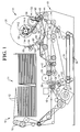
- Fig. 1 shows an automated teller machine, hereinafter designated ATM 10, in which the present invention may be used.
- Fig. 1 shows a two-ply continuous serial slip, hereinafter referred to as serial paper 12, which is stored in a paper supply area 14.
- the serial paper 12 is guided over a pin-feed tractor 16 and then is conveyed over various conventional rollers and pulleys, shown in Fig. 1, to a printer station 18.
- the printer station 18 the results of a transaction or settlement are printed in a designated position (not shown) on the serial paper 12.
- the serial paper 12 is guided onto a separation roller 20 after passing a conveyor roller 22.
- the separation roller 20 rotates in a counterclockwise direction (as viewed in Fig. 1) and causes the two plys of serial paper 12 to be separated into a serial receipt paper 24 and a serial journal paper 26.
- the serial receipt paper 24 is guided by a guide plate 28 and conveyed onto a conveyor roller 30 and then to a cutter 32.
- the serial receipt paper 24 is cut off in a designated position by the cutter 32 to form a receipt (not shown) which is then conveyed onto a conveyor roller 34 after being pinched between a conveyor belt 36 and a conveyor belt 38.
- the receipt is conveyed through a plurality of belts and rollers, as shown in Fig. 1, after passing through the conveyor roller 34 until it ultimately is issued to a customer through a port 40.
- the serial journal paper 26 which is separated by the separation roller 20 is conveyed to an imprint station 42.
- a customer card (not shown) is inserted by the customer through the port 40 and is conveyed to the imprint station 42 whereupon embossed characters or other customer data (not shown) on the card are imprinted onto the serial journal paper 26.
- various gears, belts and pulleys cooperate to move the serial journal paper 26 from the separation roller 20 to a guide roller 48.
- the serial journal paper 26 is guided over the guide roller 48 and conveyed between conveyor rollers 44 and 46 to an automatic take-up device 50.
- Fig. 2 is a fragmentary perspective view of the take-up device 50.
- the take-up device 50 includes a housing 52, a take-up spool 54 and an articulated guide module 56.
- the housing 52 includes a first side wall 52-1 which is positioned in parallel with a second side wall 52-2. The first and the second side walls 52-1 and 52-2 are secured together by various shafts as shown.
- the take-up spool 54 is rotated clockwise (as viewed in Fig. 2) by a drive motor (not shown) when the serial journal paper 26 (Fig. 1) is being rolled or taken up.
- the rate or speed of rotation of the take-up spool 54 varies with the speed at which the serial journal paper 26 is being fed thereto.
- the guide module 56 comprises a first guide plate 58 for guiding the serial journal paper 26 to the take-up spool 54.
- a second guide plate 60 is pivotably connected between the first guide plate 58 and a third guide plate 62.
- the third guide plate 62 is also pivotably connected to a fourth guide plate 64 which in turn is coupled to a fifth guide plate 66, as illustrated in Fig. 3.
- the fifth guide plate 66 has a cross section (not shown) which becomes gradually thinner towards an end 66-1 thereof. This permits the serial journal paper 26 (Fig. 1) to be easily guided to the take-up spool 54.
- a first shaft 68 is passed through holes or hinges 69 in the guide plates 58 and 60, thereby coupling the first guide plate 58 to the second guide plate 60.
- a second shaft 70 is passed through holes in the guide plates 60 and 62, thereby coupling the second guide plate 60 to the third guide plate 62.
- the third and the fourth guide plates 62 and 64 and the fourth and the fifth guide plates 64 and 66 are coupled together in a similar fashion by a third shaft 72 and a fourth shaft 74, respectively, as shown in Fig. 3.
- the shafts 68, 70, 72, and 74 have guide rollers 76, 78, 80, and 82, respectively, mounted as shown.
- the guide rollers 76, 78, 80 and 82 facilitate guiding the serial journal paper 26 around the take-up spool 54.
- a plurality of springs 84 are attached to each shaft 68, 70, 72, and 74 such that the guide plates 58, 60, 62, 64 and 66 are normally biased around the take-up spool 54, as shown in Fig. 1.
- the shafts 68, 70, 72 and 74 each have a pair of clips 86 at their ends to secure the guide plates 58, 60, 62, 64, and 66 in place.
- the guide plates 58, 60, 62, 64, and 66 each have a pair of pawls 88 to keep the guide plates from extending in a counterclockwise direction (as viewed in Figs. 1, 2 and 3).
- An end 58-1 of the first guide plate 58 is connected to the second guide plate 60, and another end 58-2 is pivotally attached onto a shaft 90 (Figs. 1 and 2).
- Shaft parts 92 and 94 (Fig. 3) protrude from opposite sides of the first guide plate 58, as illustrated in Fig. 3.
- Tension springs 96 and 98 are spanned between the shaft parts 92 and 94, respectively, and associated studs (not shown) located on the first and the second side walls 52-1 (Fig. 2) and 52-2 of the housing 52.
- the guide module 56 (Fig. 3) is always biased toward the take-up spool 54 by the tension springs 96 and 98 when the take-up spool 54 is mounted in the housing 52.
- a knob 100 (Fig. 3) is provided on an end 74-1 of the shaft 74.
- the knob 100 may be set in a knob receptor member 102 (Figs. 1 and 2) which is provided on the second side wall 52-2, thereby causing the guide module 56 to be extended to an open position, as shown in phantom outline in Fig. 1. This facilitates removing the rolled serial journal paper 26 from the automatic take-up device 50.
- the take-up spool 54 consists of a first flange member 104 and a second flange member 106.
- the first flange member 104 comprises a shaft 108, a gear 110, a flange 112, a take-up shaft 114 and a guide shaft 116.
- the take-up shaft 114 (Fig. 4) consists of parts 114-1, 114-2 and 114-3 having spaces therebetween as best shown in Fig. 1.
- An elastic friction member 118 extends slightly beyond the circumferential surface of the parts 114-1, 114-2 and 114-3 of the take-up shaft 114.
- the second flange member 106 comprises a flange 120, which has a pair of slots or holes 122 and 124.
- the hole 122 cooperates with the part 114-2 to couple the first and the second flange members 104 and 106 together.
- the hole 124 also cooperates with a similar part (not shown) as part 114-2 on the underside (as viewed in Fig. 4) of the take-up shaft 114.
- a tapered core shaft 126 having a tapered end 126-1 is also secured to the flange 120, as shown in Fig. 4, and a guide shaft (not shown) is secured to the opposite side (as viewed in Fig. 4) of the flange 120.
- the tapered core shaft 126 cooperates with a tapered opening (not shown) at an end 114-4 of the take-up shaft 114.
- the guide shaft (not shown) on flange 120 and the guide shaft 116 enable the take-up spool 54 to be rotatably mounted in bearings (not shown) in a pair of slots 53-1 (Fig. 2) and 53-2 located in side walls 52-1 and 52-2, respectively.
- the second flange member 106 (Fig. 4) is detached from the first flange member 104 when it is desired to remove the serial journal paper 26 from the take-up shaft 114.
- the shaft 108 is dismounted or pulled away from an opening 126-2 of the tapered core shaft 126, the parts 114-1, 114-2 and 114-3 become compressed towards each other by the force of the elastic friction member 118, thereby causing the outer diameter of the take-up shaft 114 to become reduced. This facilitates removing the roll of serial journal paper 26 from the take-up shaft 114.
- the tapered end 126-1 of the tapered core shaft 126 is inserted into the opening (not shown) at the end 114-4.
- the tapered core shaft 114 causes the parts 114-1, 114-2 and 114-3 to expand away from each other as the tapered end 126-1 is inserted into the end 114-4, thereby causing the outer diameter of the take-up shaft 114 to increase.
- the second flange member 106 becomes secured to the first flange member 104.
- the take-up spool 54 is first rotatably mounted in the slots 53-1 and 53-2 (Fig. 2) of side walls 52-1 and 52-2, respectively.
- the knob 100 (Fig. 3) of the guide module 56 is detached from the knob receptor member 102 (Figs. 1 and 2).
- the first guide plate 58 swings (Fig. 3) about the take-up shaft 114 by the actions of the springs 96 and 98 (Fig. 3) until the first guide plate 58 comes into contact with the take-up shaft 114 (Fig. 4).
- the guide plates 60, 62, 64 and 66 are biased to wrap around the take-up shaft 114 by the force of the springs 84, as best illustrated in Figs. 1 and 2.
- the serial journal paper 26 (Fig. 1) on which transaction data (not shown) has been printed at the printer station 18 is conveyed from the paper supply area 14 to the conveyor rollers 44 and 46.
- the conveyor rollers 44 and 46 convey the serial journal paper 26 along the first guide plate 58 (Fig. 3) until the leading edge (not shown) of the serial journal paper 26 contacts the guide roller 76 (Fig. 3) which is provided at the end 58-1 of the first guide plate 58.
- the guide roller 76 engages the serial journal paper 26 against the take-up shaft 114 of the take-up spool 54. As the take-up spool 54 rotates clockwise (as viewed in Fig. 1), the guide roller 76 is rotated counterclockwise.
- serial journal paper 26 This causes the serial journal paper 26 to be conveyed clockwise along the other guide plates 60, 62, 64, and 66 until the serial journal paper 26 is wound along the outer periphery of the take-up shaft 114.
- the slippage or idling of the serial journal paper 26 thus wound around the take-up shaft 114 is prevented by the elastic friction member 118 (Fig. 4).
- the serial journal paper 26 is wound around the outer periphery of the take-up shaft 114 as the take-up spool 54 is rotated by the drive motor (not shown).
- the serial journal paper 26 is taken up on the take-up spool 54 after the completion of each transaction, and the diameter of the rolled serial journal paper 26 gradually increases. As the diameter of the roll of serial journal paper 26 increases, the guide module 56 gradually expands to an open position, as best illustrated in phantom outline in Fig. 1. When the diameter of the rolled serial journal paper 26 reaches a predetermined size, as shown in phantom in Fig. 1, a sensor (not shown) is activated to notify an operator that the roll of serial journal paper 26 needs to be detached. Next, the detachment of the rolled serial journal paper 26 will be described.
- the knob 100 (Fig. 3) of the guide module 56 which is extended along the outside of the rolled serial journal paper 26, is lifted up in a counterclockwise direction (as viewed in Figs. 1 and 2).
- the knob 100 is fitted and secured into the knob receptor member 102 (Figs. 1 and 2).
- the take-up spool 54 can now be lifted upward (as viewed in Fig. 2) away from the slots 53-1 and 53-2 in the side walls 52-1 and 52-2, respectively.
- the second flange member 106 (Fig. 4) can be pulled in the axial direction away from the first flange member 104, thereby separating the first and the second flange members 104 and 106.
- the outer diameter of the take-up shaft 114 becomes reduced by the contraction of the elastic friction member 118 as the tapered core shaft 126 is pulled away from the take-up shaft 114, thereby facilitating removal of the rolled serial journal paper 26 from the take-up shaft 114.
- the first and the second flange members 104 and 106 can be reunited in the manner described earlier herein.
- the take-up spool 54 can again be positioned in the slots 53-1 and 53-2 of the side walls 52-1 and 52-2, respectively, where the spool 54 can take-up another roll of serial journal paper 26.
Landscapes
- Physics & Mathematics (AREA)
- General Physics & Mathematics (AREA)
- Replacement Of Web Rolls (AREA)
- Unwinding Webs (AREA)
- Handling Of Continuous Sheets Of Paper (AREA)
- Winding Of Webs (AREA)
- Registering, Tensioning, Guiding Webs, And Rollers Therefor (AREA)
Claims (7)
- Automatische Aufrollvorrichtung (50) zum Aufwickeln eines Papierstreifens auf eine Papierrollen-Aufrollspule (54), die sich in einem Gehäuse (52) befindet, wobei die genannte Aufrollvorrichtung aus einer Führung (56) besteht, und die so angeordnet ist, daß sie mit der genannten Spule (54) zusammenwirkt, um den genannten endlosen Papierstreifen um die genannte Spule (54) zu führen, dadurch gekennzeichnet, daß das genannte Führungsmittel (56) mehrere Führungselemente (58 - 66) enthält, die sich mindestens teilweise um die genannte Spule erstrecken, wobei jedes Führungselement der Serie schwenkbar mit dem oder mit jedem benachbarten Führungselement verbunden und zur genannten Spule (54) gefedert ist, so daß es in Betrieb mit der Papierrolle in Kontakt bleibt.
- Automatische Aufrollvorrichtung nach Anspruch 1, dadurch gekennzeichnet, daß jedes der genannten Führungselemente (58 - 66) eine Klinke (88) einschließt um zu vermeiden, daß die Führungselemente in einer zur genannten Spule (54) entgegengesetzten Richtung um einen unerwünschten Wert gedreht werden.
- Automatische Aufrollvorrichtung nach einem der vorstehenden Ansprüche, dadurch gekennzeichnet, daß ein erstes Führungselement (58) von mehreren schwenkbar mit dem genannten Gehäuse verbunden und zur genannten Aufrollspule (54) durch Federungsmittel (96, 98) gefedert ist, die am genannten ersten Führungselement und am genannten Gehäuse befestigt sind.
- Automatische Aufrollvorrichtung nach Anspruch 3, dadurch gekennzeichnet, daß das erste Führungselement (58) länger als die anderen Führungselemente (60, 62, 64, 66) der Reihe ist.
- Automatische Aufrollvorrichtung nach Anspruch 3 oder 4, dadurch gekennzeichnet, daß ein Führungselement (60, 62, 64, 66) außer dem genannten ersten Führungselement (58) zur genannten Spule hin durch ein entsprechendes Federungsmittel (84) auf einer Welle (74) angeordnet ist, die das Führungselement mit einem benachbarten Führungselement in der genannten Serie verbindet.
- Automatische Aufrollvorrichtung nach einem der vorstehenden Ansprüche, dadurch gekennzeichnet, daß die genannte Spule (54) aus einer Aufrollwelle (114) besteht, deren erstes Ende an einem ersten Flanschteil (104) befestigt ist und mit einem zweiten Ende (108), wobei ein zweiter Flanschteil (106) eine Welle mit konischem Kern (126) aufweist, die an diesem befestigt ist, wobei die genannte Welle mit dem konischen Kern mit dem genannten zweiten Ende (108) der genannten Aufrollwelle zusammenwirkt, um den ersten und zweiten Flanschteil miteinander zu verbinden.
- Automatische Aufrollvorrichtung nach Anspruch 6, dadurch gekennzeichnet, daß die genannte Aufrollwelle (114) aus einem ersten Teil (114-1), einem zweiten Teil (114-2) und einem dritten Teil (114-3) besteht, wobei die genannte Aufrollwelle (114) ferner einen elastischen Friktionsteil (118) enthält, der daran befestigt ist, um den genannten ersten, zweiten und dritten Teil um die genannte Welle mit konischem Kern (126) zu drücken, wenn der genannte erste Flanschteil (104) am genannten zweiten Flanschteil (106) befestigt ist und um ferner den Außendurchmesser der genannten Aufrollwelle (114) zu verkleinern, wenn der genannte erste Flanschteil (104) vom genannten zweiten Flanschteil (106) gelöst wird, so daß die genannte Papierrolle von der genannten Aufrollwelle (114) entfernt werden kann.
Applications Claiming Priority (2)
| Application Number | Priority Date | Filing Date | Title |
|---|---|---|---|
| JP324180/89 | 1989-12-15 | ||
| JP1324180A JP2736338B2 (ja) | 1989-12-15 | 1989-12-15 | 連続用紙の自動巻取装置 |
Publications (3)
| Publication Number | Publication Date |
|---|---|
| EP0433076A2 EP0433076A2 (de) | 1991-06-19 |
| EP0433076A3 EP0433076A3 (en) | 1992-01-29 |
| EP0433076B1 true EP0433076B1 (de) | 1994-06-01 |
Family
ID=18162979
Family Applications (1)
| Application Number | Title | Priority Date | Filing Date |
|---|---|---|---|
| EP90313621A Expired - Lifetime EP0433076B1 (de) | 1989-12-15 | 1990-12-14 | Automatische Aufrollvorrichtung für Endlospapier |
Country Status (4)
| Country | Link |
|---|---|
| US (1) | US5238198A (de) |
| EP (1) | EP0433076B1 (de) |
| JP (1) | JP2736338B2 (de) |
| DE (1) | DE69009415T2 (de) |
Families Citing this family (18)
| Publication number | Priority date | Publication date | Assignee | Title |
|---|---|---|---|---|
| US5370049A (en) * | 1992-07-10 | 1994-12-06 | Tohoku Richo Co., Ltd. | Thermal printer |
| CA2135421C (en) * | 1993-11-12 | 2000-09-12 | Motoaki Murakami | Continuous film take-up apparatus |
| CA2145819C (en) * | 1994-03-30 | 1999-03-09 | Motoaki Murakami | Continuous film take-up apparatus |
| US5533691A (en) * | 1994-08-18 | 1996-07-09 | Minnesota Mining And Manufacturing Company | Mandrel with twist lock apparatus |
| US5725321A (en) * | 1995-12-07 | 1998-03-10 | Interbold | Journal printer paper feed fault detection system for automated teller machine |
| EP0785080B1 (de) * | 1996-01-19 | 2001-11-28 | Seiko Epson Corporation | Druckgerät mit mehreren Druckeinrichtungen |
| FR2835514B1 (fr) * | 2002-02-05 | 2004-04-02 | Imagus | Dispositif pour l'enroulement et/ou le deroulement d'un film a vitesse constante |
| US7300220B1 (en) * | 2005-01-25 | 2007-11-27 | Unisys Corporation | Hand-separable ribbon spool assembly |
| TWM369245U (en) * | 2009-02-12 | 2009-11-21 | Hiti Digital Inc | Interlocked roll type apparatus |
| JP2011110813A (ja) * | 2009-11-27 | 2011-06-09 | Seiko Epson Corp | 記録装置、及び、記録装置の記録媒体供給構造 |
| JP5822333B2 (ja) * | 2010-06-21 | 2015-11-24 | 株式会社セイコーアイ・インフォテック | 画像形成装置 |
| CN102433663A (zh) * | 2011-09-14 | 2012-05-02 | 吴江市隆泰喷织厂 | 耳丝盘头组的紧固机构 |
| CN102321943A (zh) * | 2011-09-14 | 2012-01-18 | 吴江市隆泰喷织厂 | 耳丝盘头组 |
| CN103009828B (zh) * | 2012-12-04 | 2015-10-21 | 新达通科技股份有限公司 | 一种日志打印机自动定位收纸轴结构 |
| DE202014010142U1 (de) * | 2014-12-22 | 2016-03-27 | Poly-Clip System Gmbh & Co. Kg | Clipspule |
| CN113620127B (zh) * | 2021-10-12 | 2021-12-31 | 江苏宏远新材料科技有限公司 | 一种用于聚氨酯薄膜生产的薄膜自动收卷装置 |
| CN116676804B (zh) * | 2023-05-29 | 2024-08-30 | 江苏太得隆智能装备有限公司 | 一种长网多缸装饰纸造纸机 |
| CN118545582B (zh) * | 2024-07-29 | 2024-11-08 | 惠博新材料股份有限公司 | 一种镀锌板卷固定装置 |
Family Cites Families (21)
| Publication number | Priority date | Publication date | Assignee | Title |
|---|---|---|---|---|
| US1631432A (en) * | 1926-12-27 | 1927-06-07 | Braden Steel & Winch Company | Take-up reel |
| US2943807A (en) * | 1955-04-15 | 1960-07-05 | Continental Steel Corp | Spool mechanism |
| US2839258A (en) * | 1955-11-02 | 1958-06-17 | Delbert G Jacobson | Wire winding spool mechanism |
| US3395870A (en) * | 1966-06-16 | 1968-08-06 | Ncr Co | Automatic tape wind up means |
| US3393790A (en) * | 1966-07-29 | 1968-07-23 | Columbia Ribbon & Carbon | Ribbon spools |
| CA989799A (en) * | 1972-09-05 | 1976-05-25 | Walmsleys (Bury) Limited | Chucks |
| DE2345259A1 (de) * | 1973-09-07 | 1975-03-20 | Agfa Gevaert Ag | Automatische bandanwickelvorrichtung |
| US4117988A (en) * | 1976-04-21 | 1978-10-03 | Bedford Industries, Inc. | Reel adapter for tie material and method of using the same |
| DE2638697C3 (de) * | 1976-08-27 | 1979-09-20 | Maria 8122 Penzberg Walter | Tageslichtkassette für einen lichtempfindlichen Streifen |
| US4059211A (en) * | 1977-01-21 | 1977-11-22 | Eastman Kodak Company | Web material storage device |
| CH640065A5 (de) * | 1978-02-27 | 1983-12-15 | Agfa Gevaert Ag | Aufwickelvorrichtung fuer bandfoermiges, fotografisches material. |
| US4244535A (en) * | 1979-06-04 | 1981-01-13 | Polaroid Corporation | Separable film spool and method of loading film cassette therewith |
| US4396164A (en) * | 1980-04-11 | 1983-08-02 | Minolta Camera Kabushiki Kaisha | Easy loading mechanism for cameras |
| JPS57205731A (en) * | 1981-06-12 | 1982-12-16 | Konishiroku Photo Ind Co Ltd | Winder for photographic paper |
| DE3221221C2 (de) * | 1982-06-04 | 1987-01-22 | Agfa-Gevaert Ag, 5090 Leverkusen | Vorrichtung zum Aufwickeln von Bändern, insbesondere fotografischen Schichtträgern in Bandform |
| GB2156781B (en) * | 1984-04-07 | 1987-06-10 | Burroughs Corp | Demountable two-part reel |
| KR910000613B1 (ko) * | 1986-05-14 | 1991-01-28 | 린테크 가부시끼가이샤 | 전자부품이 장치된 기록용 테이프의 감기방법과 그 장치 |
| JPH0665575B2 (ja) * | 1987-09-01 | 1994-08-24 | 沖電気工業株式会社 | 伝票発行装置 |
| DE3729747A1 (de) * | 1987-09-04 | 1989-03-23 | Esselte Meto Int Gmbh | Dorn zum aufwickeln von bandfoermigem material |
| US4893765A (en) * | 1987-11-02 | 1990-01-16 | Randolph Glenn E | Friction core holder |
| DE3932934A1 (de) * | 1989-10-03 | 1991-04-11 | Hoechst Ag | Verfahren und vorrichtung zum wickeln einer folienbahn |
-
1989
- 1989-12-15 JP JP1324180A patent/JP2736338B2/ja not_active Expired - Lifetime
-
1990
- 1990-12-13 US US07/627,165 patent/US5238198A/en not_active Expired - Fee Related
- 1990-12-14 DE DE69009415T patent/DE69009415T2/de not_active Expired - Fee Related
- 1990-12-14 EP EP90313621A patent/EP0433076B1/de not_active Expired - Lifetime
Also Published As
| Publication number | Publication date |
|---|---|
| US5238198A (en) | 1993-08-24 |
| DE69009415T2 (de) | 1995-01-26 |
| EP0433076A2 (de) | 1991-06-19 |
| DE69009415D1 (de) | 1994-07-07 |
| JP2736338B2 (ja) | 1998-04-02 |
| JPH03186551A (ja) | 1991-08-14 |
| EP0433076A3 (en) | 1992-01-29 |
Similar Documents
| Publication | Publication Date | Title |
|---|---|---|
| EP0433076A2 (de) | Automatische Aufrollvorrichtung für Endlospapier | |
| US4629136A (en) | Demountable two-part reel | |
| DE3442814A1 (de) | Automatische papiertransportvorrichtung | |
| JPS63299957A (ja) | プリンタの紙送り装置 | |
| JPH0136434B2 (de) | ||
| JPH021679B2 (de) | ||
| US4353543A (en) | Sorter connection apparatus | |
| JPS6183073A (ja) | 印字装置の用紙送り方法 | |
| EP1661837B1 (de) | Bogenausgabesystem | |
| EP0712729A2 (de) | Blattzuführeinheit | |
| US5046713A (en) | Document imprinting device | |
| JP2547978B2 (ja) | シート材給送装置 | |
| JPS6139570Y2 (de) | ||
| KR100365326B1 (ko) | 현금자동지급기저널프린트부유니트의기록지자동로딩방법및그장치 | |
| JPS63246266A (ja) | プリンタ | |
| JP3993312B2 (ja) | 印字装置のシート回収装置 | |
| US2622898A (en) | Tamperproof pocket autographic register | |
| JPH03111372A (ja) | シート集積装置 | |
| JPH0225800Y2 (de) | ||
| US4136614A (en) | Letterpress printing press | |
| WO1997022477A1 (en) | Device for the automatic loading of a paper roll in a printing device and relative printing device | |
| JP4750292B2 (ja) | 発券装置 | |
| JPH0360319B2 (de) | ||
| JP2001001486A (ja) | 製版装置 | |
| JP2842563B2 (ja) | 用紙搬送装置 |
Legal Events
| Date | Code | Title | Description |
|---|---|---|---|
| PUAI | Public reference made under article 153(3) epc to a published international application that has entered the european phase |
Free format text: ORIGINAL CODE: 0009012 |
|
| AK | Designated contracting states |
Kind code of ref document: A2 Designated state(s): DE GB |
|
| PUAL | Search report despatched |
Free format text: ORIGINAL CODE: 0009013 |
|
| AK | Designated contracting states |
Kind code of ref document: A3 Designated state(s): DE GB |
|
| RHK1 | Main classification (correction) |
Ipc: B65H 18/00 |
|
| 17P | Request for examination filed |
Effective date: 19920629 |
|
| 17Q | First examination report despatched |
Effective date: 19931110 |
|
| GRAA | (expected) grant |
Free format text: ORIGINAL CODE: 0009210 |
|
| RAP1 | Party data changed (applicant data changed or rights of an application transferred) |
Owner name: NCR INTERNATIONAL INC. |
|
| AK | Designated contracting states |
Kind code of ref document: B1 Designated state(s): DE GB |
|
| REF | Corresponds to: |
Ref document number: 69009415 Country of ref document: DE Date of ref document: 19940707 |
|
| PLBE | No opposition filed within time limit |
Free format text: ORIGINAL CODE: 0009261 |
|
| STAA | Information on the status of an ep patent application or granted ep patent |
Free format text: STATUS: NO OPPOSITION FILED WITHIN TIME LIMIT |
|
| 26N | No opposition filed | ||
| PGFP | Annual fee paid to national office [announced via postgrant information from national office to epo] |
Ref country code: GB Payment date: 20000914 Year of fee payment: 11 |
|
| PGFP | Annual fee paid to national office [announced via postgrant information from national office to epo] |
Ref country code: DE Payment date: 20001221 Year of fee payment: 11 |
|
| PG25 | Lapsed in a contracting state [announced via postgrant information from national office to epo] |
Ref country code: GB Free format text: LAPSE BECAUSE OF NON-PAYMENT OF DUE FEES Effective date: 20011214 |
|
| REG | Reference to a national code |
Ref country code: GB Ref legal event code: IF02 |
|
| PG25 | Lapsed in a contracting state [announced via postgrant information from national office to epo] |
Ref country code: DE Free format text: LAPSE BECAUSE OF NON-PAYMENT OF DUE FEES Effective date: 20020702 |
|
| GBPC | Gb: european patent ceased through non-payment of renewal fee |
Effective date: 20011214 |