EP0431280B1 - Wickelmaschine für bandförmiges Material, insbesondere für einen beim Besäumen von Bändern anfallenden Saumstreifen - Google Patents
Wickelmaschine für bandförmiges Material, insbesondere für einen beim Besäumen von Bändern anfallenden Saumstreifen Download PDFInfo
- Publication number
- EP0431280B1 EP0431280B1 EP90119361A EP90119361A EP0431280B1 EP 0431280 B1 EP0431280 B1 EP 0431280B1 EP 90119361 A EP90119361 A EP 90119361A EP 90119361 A EP90119361 A EP 90119361A EP 0431280 B1 EP0431280 B1 EP 0431280B1
- Authority
- EP
- European Patent Office
- Prior art keywords
- shaft
- hollow shaft
- winding
- drive
- winding machine
- Prior art date
- Legal status (The legal status is an assumption and is not a legal conclusion. Google has not performed a legal analysis and makes no representation as to the accuracy of the status listed.)
- Expired - Lifetime
Links
Images
Classifications
-
- B—PERFORMING OPERATIONS; TRANSPORTING
- B21—MECHANICAL METAL-WORKING WITHOUT ESSENTIALLY REMOVING MATERIAL; PUNCHING METAL
- B21C—MANUFACTURE OF METAL SHEETS, WIRE, RODS, TUBES, PROFILES OR LIKE SEMI-MANUFACTURED PRODUCTS OTHERWISE THAN BY ROLLING; AUXILIARY OPERATIONS USED IN CONNECTION WITH METAL-WORKING WITHOUT ESSENTIALLY REMOVING MATERIAL
- B21C47/00—Winding-up, coiling or winding-off metal wire, metal band or other flexible metal material characterised by features relevant to metal processing only
- B21C47/28—Drums or other coil-holders
-
- B—PERFORMING OPERATIONS; TRANSPORTING
- B23—MACHINE TOOLS; METAL-WORKING NOT OTHERWISE PROVIDED FOR
- B23D—PLANING; SLOTTING; SHEARING; BROACHING; SAWING; FILING; SCRAPING; LIKE OPERATIONS FOR WORKING METAL BY REMOVING MATERIAL, NOT OTHERWISE PROVIDED FOR
- B23D21/00—Machines or devices for shearing or cutting tubes
- B23D21/04—Tube-severing machines with rotating tool-carrier
-
- B—PERFORMING OPERATIONS; TRANSPORTING
- B65—CONVEYING; PACKING; STORING; HANDLING THIN OR FILAMENTARY MATERIAL
- B65H—HANDLING THIN OR FILAMENTARY MATERIAL, e.g. SHEETS, WEBS, CABLES
- B65H18/00—Winding webs
- B65H18/08—Web-winding mechanisms
- B65H18/10—Mechanisms in which power is applied to web-roll spindle
-
- B—PERFORMING OPERATIONS; TRANSPORTING
- B65—CONVEYING; PACKING; STORING; HANDLING THIN OR FILAMENTARY MATERIAL
- B65H—HANDLING THIN OR FILAMENTARY MATERIAL, e.g. SHEETS, WEBS, CABLES
- B65H2301/00—Handling processes for sheets or webs
- B65H2301/40—Type of handling process
- B65H2301/41—Winding, unwinding
- B65H2301/413—Supporting web roll
- B65H2301/4134—Both ends type arrangement
- B65H2301/41342—Both ends type arrangement shaft transversing the roll
-
- B—PERFORMING OPERATIONS; TRANSPORTING
- B65—CONVEYING; PACKING; STORING; HANDLING THIN OR FILAMENTARY MATERIAL
- B65H—HANDLING THIN OR FILAMENTARY MATERIAL, e.g. SHEETS, WEBS, CABLES
- B65H2301/00—Handling processes for sheets or webs
- B65H2301/40—Type of handling process
- B65H2301/41—Winding, unwinding
- B65H2301/413—Supporting web roll
- B65H2301/4136—Mounting arrangements not otherwise provided for
- B65H2301/41368—Mounting arrangements not otherwise provided for one or two lateral flanges covering part of or entire web diameter
-
- B—PERFORMING OPERATIONS; TRANSPORTING
- B65—CONVEYING; PACKING; STORING; HANDLING THIN OR FILAMENTARY MATERIAL
- B65H—HANDLING THIN OR FILAMENTARY MATERIAL, e.g. SHEETS, WEBS, CABLES
- B65H2701/00—Handled material; Storage means
- B65H2701/10—Handled articles or webs
- B65H2701/17—Nature of material
- B65H2701/173—Metal
-
- B—PERFORMING OPERATIONS; TRANSPORTING
- B65—CONVEYING; PACKING; STORING; HANDLING THIN OR FILAMENTARY MATERIAL
- B65H—HANDLING THIN OR FILAMENTARY MATERIAL, e.g. SHEETS, WEBS, CABLES
- B65H2701/00—Handled material; Storage means
- B65H2701/10—Handled articles or webs
- B65H2701/18—Form of handled article or web
- B65H2701/184—Wound packages
- B65H2701/1846—Parts concerned
Definitions
- the invention relates to a winding machine for band-shaped material according to the preamble of claim 1.
- Such a winding machine is known from DE-C-1 097 937.
- the side window facing away from the hollow shaft is connected to the axially displaceable winding shaft via a positive plug-in coupling.
- a winding machine has the advantage that the wound-up hem scrap can be ejected simply by pulling the winding shaft out of the area between the side windows. Assembly work on the side windows is therefore not necessary.
- this advantage is offset by the disadvantage that the coupling between the winding shaft and the side disc remote from the hollow shaft is subject to high wear, because, particularly in winding machines with a large disc diameter, the inertial mass of the side disc to be accelerated and braked via the coupling is great.
- This known winding machine consists of an axially adjustable, driven winding shaft and driven side disks rotatably mounted in lateral bearing blocks.
- the winding shaft is axially displaceable in an axially fixed hollow shaft and is coupled to the hollow shaft via a clutch for transmitting the torque.
- the side disks are driven as a result of the friction of the sleeve elements connected to the side disks with the driven winding shaft.
- this frictional drive has the disadvantage of high wear, in particular due to the transmission of the very high initial torque during winding and when the winding shaft is stopped, due to the inertia mass of the large diameter side discs.
- the invention has for its object to provide a winding machine of the type mentioned and described in more detail above, in which the drive synchronism between the winding shaft and the two side plates is guaranteed in the long run.
- the other side disk facing away from the hollow shaft is driven in a form-fitting manner. Because of the positive drive, the manufacturing effort is greater, but in the long run the effort is lower due to the lack of maintenance due to the significantly lower wear in the winding machine according to the invention.
- a positive coupling for transmitting a torque is provided between the winding shaft in the operating position and the other side disc.
- the torque is transmitted in parallel.
- the direct drive can be comparatively weak. It only needs for the torque difference, which in the case of the conventional clutch, which was provided exclusively between the winding shaft and the other side disc, led to its premature wear due to overload, and at two separate drives to be designed for speed synchronization.
- the common drive for the hollow shaft and the other side plate has a drive shaft arranged parallel to the winding shaft, which is connected via drive elements on the one hand to the hollow shaft and on the other hand to the other side plate.
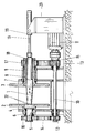
- the drawing schematically shows in axial section a winding machine for the hem scrap resulting from trimming scissors of the tapes.
- the winding machine has a conical winding shaft 1 and two side disks 2, 3 arranged on both ends of the winding shaft 1.
- the side window 2 is fastened to a flange 4 of a drive shaft 5 which is rotatably but axially immovably mounted in a bearing block 6.
- the side window 3 is fastened to a flange 7 of a hollow shaft 8 serving as a drive shaft, which is rotatably but axially fixed in a bearing block 9.
- a drive shaft 10 is mounted parallel to the winding shaft 1, which is driven by a drive motor 11 and which has drive elements 12, 13, drive belts 14, 15 and drive rollers 16, 17 on it via drive elements
- Drive shaft 5 and the hollow shaft 8 is drivingly connected to the side windows 2,3.
- the conical winding shaft 1 is via an intermediate piece 18 in the hollow shaft 8 with a cylinder piston unit 19 Adjusting device, which is held in a stand 20, axially displaceably mounted in the hollow shaft 8, so that it can be completely pulled out of the area between the side windows 2, 3.
- a positive coupling in the form of a feather key is provided between the hollow shaft 8 and the winding shaft 1.
- the winding shaft 1 is therefore also taken along.
- the winding shaft 1 On its end face, the winding shaft 1 has claws 22 which engage in a form-fitting manner in corresponding recesses in the flange 4.
Landscapes
- Engineering & Computer Science (AREA)
- Mechanical Engineering (AREA)
- Winding Of Webs (AREA)
- Winding, Rewinding, Material Storage Devices (AREA)
- Controlling Rewinding, Feeding, Winding, Or Abnormalities Of Webs (AREA)
- Package Frames And Binding Bands (AREA)
Description
- Die Erfindung bezieht sich auf eine Wickelmaschine für bandförmiges Material gemäß Oberbegriff des Anspruches 1.
- Eine derartige Wickelmaschine ist aus der DE-C-1 097 937 bekannt.
- Bei einer aus der Praxis bekannten Wickelmaschine ist die der Hohlwelle abgewandte Seitenscheibe über eine formschlüssige Steckkupplung mit der axial verschiebbaren Wickelwelle verbunden. Eine solche Wickelmaschine hat den Vorteil, daß sich der aufgewickelte Saumschrott allein durch Herausziehen der Wickelwelle aus dem Bereich zwischen den Seitenscheiben auswerfen läßt. Montagearbeiten an den Seitenscheiben sind also nicht erforderlich. Wie sich beim praktischen Betrieb herausgestellt hat, steht diesem Vorteil der Nachteil gegenüber, daß die Kupplung zwischen der Wickelwelle und der der Hohlwelle abgelegenen Seitenscheibe einem hohen Verschleiß unterliegt, weil insbesondere bei Wickelmaschinen mit großem Scheibendurchmesser die Trägheitsmasse der über die Kupplung zu beschleunigenden und abzubremsenden Seitenscheibe groß ist. Aber nicht nur die Kupplung, sondern auch die Seitenscheibe selbst unterliegt einem hohen Verschleiß, denn nach dem Anwickeln wird das Drehmoment im wesentlichen zwischen der Seitenscheibe und den Seitenkanten des aufzuwickelnden Bandes übertragen. Ist die Kupplung nicht mehr wirksam, kommt es zu einer Reibung zwischen der Seitenscheibe und den Kanten des aufgewickelten Saumschrottes und damit zu einem Verschleiß.
- Eine andere Wickelmaschine für bandförmiges Schrottmaterial ist in der DE-PS 10 97 937 beschrieben. Diese bekannte Wickelmaschine besteht aus einer axial verstellbaren, angetriebenen Wickelwelle und in seitlichen Lagerböcken drehbar gelagerten, angetriebenen Seitenscheiben. Bei dieser gattungsgemäßen Wickelmaschine ist die Wickelwelle in einer axial fixierten Hohlwelle axial verschiebbar und mit der Hohlwelle über eine Kupplung zur Übertragung des Drehmomentes gekuppelt. Hierbei erfolgt der Antrieb der Seitenscheiben infolge der Reibung der mit den Seitenscheiben verbundenen Muffenelemente mit der angetriebenen Wickelwelle. Dieser reibschlüssige Antrieb hat jedoch den Nachteil eines hohen Verschleißes, insbesondere durch die Übertragung des sehr hohen Anfangs-Drehmoments beim Anwickeln und beim Stillsetzen der Wickelwelle, bedingt durch die Trägheitsmasse der einen großen Durchmesser aufweisenden Seitenscheiben.
- Der Erfindung liegt die Aufgabe zugrunde, eine Wickelmaschine der eingangs genannten und zuvor näher beschriebenen Art zu schaffen, bei der der antriebsmäßige Gleichlauf zwischen der Wickelwelle und den beiden Seitenscheiben auf Dauer gewährleistet ist.
- Diese Aufgabe wird erfindungsgemäß dadurch gelöst, daß die der Hohlwelle abgewandte andere Seitenscheibe über einen weiteren Antriebszug entweder unmittelbar mit dem die Hohlwelle antreibenden Antrieb oder einem weiteren Antrieb drehstarr verbunden ist.
- Bei der erfindungsgemäßen Wickelmaschine erfolgt also der Antrieb der der Hohlwelle abgewandten anderen Seitenscheibe formschlüssig. Wegen des formschlüssigen Antriebes ist zwar der Herstellungsaufwand größer, auf die Dauer gesehen ist der Aufwand aber wegen des wegfallenden Instandhaltungsaufwandes durch den bei der erfindungsgemäßen Wickelmaschine deutlich geringeren Verschleiß geringer.
- Besonders vorteilhaft ist es, wenn zusätzlich zwischen der in Betriebsstellung befindlichen Wickelwelle und der anderen Seitenscheibe eine, insbesondere formschlüssige Kupplung zur Übertragung eines Drehmomentes vorgesehen ist. Bei dieser Ausgestaltung erfolgt also die Übertragung des Drehmomentes parallel. Das bedeutet, daß der direkte Antrieb vergleichsweise schwach dimensioniert sein kann. Er braucht lediglich für die Drehmomentdifferenz, die bei der herkömmlichen, ausschließlich zwischen der Wickelwelle und der anderen Seitenscheibe vorgesehenen Kupplung zu deren frühzeitigem Verschleiß wegen Überlastung führte, und bei zwei separaten Antrieben für die Drehzahlsynchronisation ausgelegt zu sein.
- Nach einer weiteren Ausgestaltung der Erfindung weist der gemeinsame Antrieb für die Hohlwelle und die andere Seitenscheibe eine parallel zur Wickelwelle angeordnete Antriebswelle auf, die über Antriebselemente einerseits mit der Hohlwelle und andererseits mit der anderen Seitenscheibe antriebsmäßig verbunden ist.
- Im folgenden wird die Erfindung anhand einer ein Ausführungsbeispiel darstellenden Zeichnung näher erläutert.
- Die Zeichnung zeigt im Axialschnitt schematisch eine Wickelmaschine für den bei Besäumscheren der Bänder anfallenden Saumschrott.
- Die Wickelmaschine weist eine konische Wickelwelle 1 und zwei an beiden Enden der Wickelwelle 1 angeordnete Seitenscheiben 2,3 auf. Die Seitenscheibe 2 ist auf einem Flansch 4 einer Antriebswelle 5 befestigt, die in einem Lagerbock 6 drehbar aber axial unverschieblich gelagert ist. Die Seitenscheibe 3 ist an einem Flansch 7 einer als Antriebswelle dienenden Hohlwelle 8 befestigt, die drehbar aber axial fest in einem Lagerbock 9 gelagert ist. In den Lagerböcken 6,9 ist eine parallel zur Wickelwelle 1 angeordnete Antriebswelle 10 gelagert, die von einem Antriebsmotor 11 angetrieben ist und die über Antriebselemente, und zwar auf ihr sitzende Treibrollen 12,13, Treibriemen 14,15 und Treibrollen 16,17 auf der Antriebswelle 5 und der Hohlwelle 8 antriebsmäßig mit den Seitenscheiben 2,3 verbunden ist.
- Die konische Wickelwelle 1 ist über ein Zwischenstück 18 in der Hohlwelle 8 mit einer Zylinderkolbeneinheit 19 als Stellvorrichtung, die in einem Ständer 20 gehalten ist, axial verschiebbar in der Hohlwelle 8 gelagert, so daß sie aus dem Bereich zwischen den Seitenscheiben 2,3 völlig herausziehbar ist. Zwischen der Hohlwelle 8 und der Wickelwelle 1 ist eine formschlüssige Kupplung in Form einer Paßfeder vorgesehen. Bei Antrieb der Hohlwelle 8 wird deshalb auch die Wickelwelle 1 mitgenommen. An ihrer Stirnseite weist die Wickelwelle 1 Klauen 22 auf, die formschlüssig in entsprechende Ausnehmungen des Flansches 4 eingreifen. Auf diese Art und Weise wird erreicht, daß ein Drehmoment vom Antrieb 11 nicht nur unmittelbar über die Antriebswelle 10 auf die Seitenscheibe 2, sondern auch mittelbar über die Hohlwelle 8 und die Wickelwelle 1 auf die Seitenscheibe 3 übertragen wird. Bei der Dimensionierung der beiden parallelen Antriebe kann diese Aufteilung des zu übertragenden Drehmomentes mit dem Ziel berücksichtigt werden, daß der direkte Antrieb über die Antriebswelle 10 möglichst klein gehalten wird, daß aber die Kupplung zwischen der Wickelwelle 1 und der Seitenscheibe 2 nicht überlastet wird.
Claims (3)
- Wickelmaschine für bandförmiges Material, insbesondere für einen beim Besäumen von Bindern anfallenden Saumstreifen, bestehend aus einer axial verstellbaren, angetriebenen Wickelwelle (1) und in seitlichen Lagerböcken (6,9) drehbar gelagerten, angetriebenen Seitenscheiben (2,3), wobei die Wickelwelle (1), die in einer unmittelbar angetriebenen, in einem der seitlichen Lagerböcke (9) gelagerten, axial fixierten Hohlwelle (8) über eine, insbesondere formschlüssige Kupplung zur Übertragung des Drehmomentes gekuppelt ist, aus dem Bereich zwischen den Seitenscheiben (2,3) herausziehbar ist, und wobei die der Hohlwelle (8) benachbarte eine Seitenscheibe (3) auf der Hohlwelle (8) fixiert ist,
dadurch gekennzeichnet , daß die der Hohlwelle (8) abgewandte andere Seitenscheibe (2) über einen weiteren Antriebszug entweder unmittelbar mit dem die Hohlwelle (8) antreibenden Antrieb (11) oder einem weiteren Antrieb drehstarr verbunden ist. - Wickelmaschine nach Anspruch 1,
dadurch gekennzeichnet , daß zwischen der in Betriebsstellung befindlichen Wickelwelle (1) und der anderen Seitenscheibe (2) eine, insbesondere formschlüssige Kupplung zur Übertragung des Drehmomentes vorgesehen ist. - Wickelmaschine nach Anspruch 1 oder 2,
dadurch gekennzeichnet , daß der gemeinsame Antrieb (11) für die Hohlwelle (8) und die andere Seitenscheibe (2) eine parallel zur Wickelwelle angeordnete Antriebswelle (10) aufweist, die über Antriebselemente (12-17) einerseits mit der Hohlwelle (8) und andererseits mit der anderen Seitenscheibe (2) antriebsmäßig verbunden ist.
Priority Applications (1)
| Application Number | Priority Date | Filing Date | Title |
|---|---|---|---|
| AT90119361T ATE89531T1 (de) | 1989-11-15 | 1990-10-09 | Wickelmaschine fuer bandfoermiges material, insbesondere fuer einen beim besaeumen von baendern anfallenden saumstreifen. |
Applications Claiming Priority (2)
| Application Number | Priority Date | Filing Date | Title |
|---|---|---|---|
| DE3937992A DE3937992C1 (de) | 1989-11-15 | 1989-11-15 | |
| DE3937992 | 1989-11-15 |
Publications (2)
| Publication Number | Publication Date |
|---|---|
| EP0431280A1 EP0431280A1 (de) | 1991-06-12 |
| EP0431280B1 true EP0431280B1 (de) | 1993-05-19 |
Family
ID=6393586
Family Applications (1)
| Application Number | Title | Priority Date | Filing Date |
|---|---|---|---|
| EP90119361A Expired - Lifetime EP0431280B1 (de) | 1989-11-15 | 1990-10-09 | Wickelmaschine für bandförmiges Material, insbesondere für einen beim Besäumen von Bändern anfallenden Saumstreifen |
Country Status (7)
| Country | Link |
|---|---|
| US (1) | US5110063A (de) |
| EP (1) | EP0431280B1 (de) |
| JP (1) | JPH03184620A (de) |
| AT (1) | ATE89531T1 (de) |
| DE (2) | DE3937992C1 (de) |
| ES (1) | ES2042171T3 (de) |
| RU (1) | RU2050997C1 (de) |
Families Citing this family (25)
| Publication number | Priority date | Publication date | Assignee | Title |
|---|---|---|---|---|
| JPH054763A (ja) * | 1990-12-21 | 1993-01-14 | Yoshida Kogyo Kk <Ykk> | テープ状体の収納箱内への巻取り方法と装置 |
| US6161604A (en) * | 1995-04-24 | 2000-12-19 | Heidelberger Druckmaschinen Ag | Web-up apparatus and method |
| GB2324079B (en) * | 1995-04-24 | 1999-03-31 | Heidelberger Druckmasch Ag | Web-fed printing press with web-up apparatus and method |
| JP4194510B2 (ja) * | 2004-03-10 | 2008-12-10 | 株式会社西村製作所 | 巻取装置 |
| CN101181726B (zh) * | 2007-12-14 | 2010-06-02 | 中冶南方工程技术有限公司 | 酸洗机组切边废料卷取装置 |
| CN101181725B (zh) * | 2007-12-14 | 2010-06-09 | 中冶南方工程技术有限公司 | 废边卷取机 |
| JP5441608B2 (ja) * | 2009-10-14 | 2014-03-12 | 日新製鋼株式会社 | スクラップ回収装置 |
| CN101875455B (zh) * | 2010-03-18 | 2012-07-04 | 无锡平盛科技有限公司 | 工字轮收线机上的主轴部件 |
| CN102485622A (zh) * | 2010-12-02 | 2012-06-06 | 张家港华明机械有限公司 | 一种收卷装置 |
| CN102390756B (zh) * | 2011-06-30 | 2012-12-19 | 河南恒星科技股份有限公司 | 工字轮气动顶紧装置 |
| CN102500643A (zh) * | 2011-09-30 | 2012-06-20 | 山东电力设备有限公司 | 硅钢边料收卷机 |
| CN102615104B (zh) * | 2012-03-30 | 2015-04-08 | 郑州市华驰薄板科技有限公司 | 冷轧带钢废边卷取机 |
| CN103071701B (zh) * | 2013-02-19 | 2015-07-15 | 中冶赛迪工程技术股份有限公司 | 废边卷取机 |
| DE102013216375A1 (de) | 2013-08-19 | 2015-02-19 | Sms Siemag Ag | Saumwickler für bandförmiges Material |
| CN105984753B (zh) * | 2015-02-27 | 2019-09-13 | 上海电缆研究所有限公司 | 放带盘恒张力控制装置 |
| MX391946B (es) * | 2015-05-05 | 2025-03-21 | Amut Spa | Maquina y metodo para producir bobinas de pelicula extensible. |
| CN105692278A (zh) * | 2016-03-10 | 2016-06-22 | 四川雅豪房地产开发有限公司 | 一种用于建材打包捆扎钢带的生产装置 |
| CN105817496A (zh) * | 2016-03-17 | 2016-08-03 | 苏州金钜松机电有限公司 | 一种微调伸线机收线盘 |
| CN105598207A (zh) * | 2016-03-17 | 2016-05-25 | 苏州金钜松机电有限公司 | 一种易于拆卸的伸线机收线盘 |
| CN106276364A (zh) * | 2016-10-19 | 2017-01-04 | 贵州恒瑞辰科技股份有限公司 | 一种卷纸轴抽出机构 |
| CN106829584A (zh) * | 2017-03-21 | 2017-06-13 | 安徽众源新材料股份有限公司 | 一种铜带保护层回收装置及其回收再利用方法 |
| CN109719159A (zh) * | 2019-01-15 | 2019-05-07 | 吴贝尔 | 一种带张力卷取的冷轧带钢废边卷取机 |
| CN110125354A (zh) * | 2019-05-24 | 2019-08-16 | 天津中晟泰新能源科技有限公司 | 一种非晶带材喷制收卷装置 |
| CN110586686B (zh) * | 2019-09-23 | 2024-05-31 | 河南明睿达机械制造有限公司 | 一种单边焊管收料设备 |
| CN110817524B (zh) * | 2019-12-09 | 2024-07-12 | 国投曹妃甸港口有限公司 | 一种使用方便的废旧输送带卷取机 |
Family Cites Families (8)
| Publication number | Priority date | Publication date | Assignee | Title |
|---|---|---|---|---|
| US2066377A (en) * | 1935-10-17 | 1937-01-05 | Wean Engineering Co Inc | Coil holder |
| US2420936A (en) * | 1944-12-06 | 1947-05-20 | Floyd E Davis | Flying coiler |
| US2829845A (en) * | 1955-04-15 | 1958-04-08 | Continental Steel Corp | Coil winding apparatus |
| US2968448A (en) * | 1957-10-29 | 1961-01-17 | David A Drum | Pinless lap winder |
| GB882728A (en) * | 1958-07-24 | 1961-11-15 | Head Wrightson & Co Ltd | Improvements in scrap metal balling machines |
| US3132820A (en) * | 1961-01-13 | 1964-05-12 | Richard F Toll | Bulk roof stock recoiler |
| US4105172A (en) * | 1977-03-11 | 1978-08-08 | Mesta Machine Company | Tension reel for strip coiling |
| DE2844882A1 (de) * | 1978-10-14 | 1980-04-30 | Schloemann Siemag Ag | Haspelvorrichtung zum aufwickeln von saumstreifen |
-
1989
- 1989-11-15 DE DE3937992A patent/DE3937992C1/de not_active Expired - Lifetime
-
1990
- 1990-10-09 DE DE9090119361T patent/DE59001494D1/de not_active Expired - Fee Related
- 1990-10-09 ES ES199090119361T patent/ES2042171T3/es not_active Expired - Lifetime
- 1990-10-09 AT AT90119361T patent/ATE89531T1/de not_active IP Right Cessation
- 1990-10-09 EP EP90119361A patent/EP0431280B1/de not_active Expired - Lifetime
- 1990-10-17 US US07/599,339 patent/US5110063A/en not_active Expired - Fee Related
- 1990-11-14 JP JP2306343A patent/JPH03184620A/ja active Pending
- 1990-11-14 RU SU904831620A patent/RU2050997C1/ru active
Also Published As
| Publication number | Publication date |
|---|---|
| DE3937992C1 (de) | 1991-02-21 |
| ATE89531T1 (de) | 1993-06-15 |
| JPH03184620A (ja) | 1991-08-12 |
| EP0431280A1 (de) | 1991-06-12 |
| US5110063A (en) | 1992-05-05 |
| RU2050997C1 (ru) | 1995-12-27 |
| DE59001494D1 (de) | 1993-06-24 |
| ES2042171T3 (es) | 1993-12-01 |
Similar Documents
| Publication | Publication Date | Title |
|---|---|---|
| EP0431280B1 (de) | Wickelmaschine für bandförmiges Material, insbesondere für einen beim Besäumen von Bändern anfallenden Saumstreifen | |
| CH645431A5 (de) | Lamellenjalousie mit senkrecht angeordneten lamellen. | |
| DE2522446B2 (de) | Sicherungsrutschkupplung für Handbohrmaschine | |
| CH636319A5 (de) | Haspel zum abwickeln von baendern oder straengen. | |
| EP0191730B1 (de) | Türantrieb zum vollautomatischen Öffnen und Schliessen einer Türe | |
| EP0036645B2 (de) | Kupplungs- und Bremsvorrichtung für Pressen, Stanzen u.dgl. | |
| DE2711752A1 (de) | Kupplungsvorrichtung, insbesondere zur steuerung des garnspulenantriebs bei textilmaschinen | |
| DE4407416C2 (de) | Sicherungsvorrichtung gegen den Absturz von motorisch auf- und abbewegbaren Objekten | |
| EP0638376B1 (de) | Vorrichtung zum steuerbaren Befetten von Werkstücken mit über einen Riementrieb und eine Antriebswelle von einem Motor gedrehten Befettungswalzen | |
| DE69821561T2 (de) | Seilwinde mit versetztem Antrieb | |
| DE938603C (de) | Drehbohrmaschine, insbesondere Gesteinsdrehbohrmaschine | |
| DE3641654C2 (de) | ||
| DE2853460A1 (de) | Wickelvorrichtung | |
| DE68902405T2 (de) | Verzoegerungsvorrichtung fuer getriebeschaltung. | |
| DE2743982A1 (de) | Vorrichtung zum bewegen von fensterscheiben, schiebedaechern u.dgl. von kraftfahrzeugen | |
| DE102007011280B4 (de) | Fliehkraftkupplung | |
| DE1042311B (de) | Vorrichtung fuer Antriebe, insbesondere Stellantriebe fuer Drosselklappen, Ventile, Schleusen u. dgl. | |
| DE4425576A1 (de) | Werkzeugmaschine | |
| DE1506473B1 (de) | Fangvorrichtung fuer Bau- und aehnliche Aufzuege | |
| DE1480686C (de) | Fliehkraftkupplung, insbesondere für Kraftfahrzeuge | |
| EP0131225B1 (de) | Antriebsvorrichtung für Jalousien oder dergleichen | |
| DE2818411A1 (de) | Antriebseinrichtung fuer eine vorrichtung zum kontinuierlichen recken von baendern und draehten | |
| DE3137517C2 (de) | Antrieb für ein Magnetbandgerät | |
| DE2554991A1 (de) | Antriebseinrichtung fuer die lamellen einer jalousie | |
| DE3008521A1 (de) | Fraesmaschine zum einfraesen von ausnehmungen in profilstuecke fuer tuer- oder fensterrahmen |
Legal Events
| Date | Code | Title | Description |
|---|---|---|---|
| PUAI | Public reference made under article 153(3) epc to a published international application that has entered the european phase |
Free format text: ORIGINAL CODE: 0009012 |
|
| AK | Designated contracting states |
Kind code of ref document: A1 Designated state(s): AT BE DE ES FR GB IT NL SE |
|
| 17P | Request for examination filed |
Effective date: 19910810 |
|
| 17Q | First examination report despatched |
Effective date: 19911007 |
|
| GRAA | (expected) grant |
Free format text: ORIGINAL CODE: 0009210 |
|
| AK | Designated contracting states |
Kind code of ref document: B1 Designated state(s): AT BE DE ES FR GB IT NL SE |
|
| PG25 | Lapsed in a contracting state [announced via postgrant information from national office to epo] |
Ref country code: SE Effective date: 19930519 Ref country code: NL Effective date: 19930519 |
|
| REF | Corresponds to: |
Ref document number: 89531 Country of ref document: AT Date of ref document: 19930615 Kind code of ref document: T |
|
| GBT | Gb: translation of ep patent filed (gb section 77(6)(a)/1977) |
Effective date: 19930514 |
|
| ET | Fr: translation filed | ||
| REF | Corresponds to: |
Ref document number: 59001494 Country of ref document: DE Date of ref document: 19930624 |
|
| ITF | It: translation for a ep patent filed | ||
| PGFP | Annual fee paid to national office [announced via postgrant information from national office to epo] |
Ref country code: AT Payment date: 19931001 Year of fee payment: 4 |
|
| NLV1 | Nl: lapsed or annulled due to failure to fulfill the requirements of art. 29p and 29m of the patents act | ||
| REG | Reference to a national code |
Ref country code: ES Ref legal event code: FG2A Ref document number: 2042171 Country of ref document: ES Kind code of ref document: T3 |
|
| PLBE | No opposition filed within time limit |
Free format text: ORIGINAL CODE: 0009261 |
|
| STAA | Information on the status of an ep patent application or granted ep patent |
Free format text: STATUS: NO OPPOSITION FILED WITHIN TIME LIMIT |
|
| 26N | No opposition filed | ||
| PG25 | Lapsed in a contracting state [announced via postgrant information from national office to epo] |
Ref country code: AT Effective date: 19941009 |
|
| PGFP | Annual fee paid to national office [announced via postgrant information from national office to epo] |
Ref country code: FR Payment date: 19951017 Year of fee payment: 6 |
|
| PGFP | Annual fee paid to national office [announced via postgrant information from national office to epo] |
Ref country code: GB Payment date: 19951019 Year of fee payment: 6 |
|
| PGFP | Annual fee paid to national office [announced via postgrant information from national office to epo] |
Ref country code: ES Payment date: 19951031 Year of fee payment: 6 |
|
| PGFP | Annual fee paid to national office [announced via postgrant information from national office to epo] |
Ref country code: BE Payment date: 19951129 Year of fee payment: 6 |
|
| PG25 | Lapsed in a contracting state [announced via postgrant information from national office to epo] |
Ref country code: GB Effective date: 19961009 |
|
| PG25 | Lapsed in a contracting state [announced via postgrant information from national office to epo] |
Ref country code: ES Free format text: LAPSE BECAUSE OF THE APPLICANT RENOUNCES Effective date: 19961010 |
|
| PG25 | Lapsed in a contracting state [announced via postgrant information from national office to epo] |
Ref country code: BE Effective date: 19961031 |
|
| BERE | Be: lapsed |
Owner name: SUNDWIGER EISENHUTTE MASCHINENFABRIK G.M.B.H. & C Effective date: 19961031 |
|
| GBPC | Gb: european patent ceased through non-payment of renewal fee |
Effective date: 19961009 |
|
| PG25 | Lapsed in a contracting state [announced via postgrant information from national office to epo] |
Ref country code: FR Effective date: 19970630 |
|
| REG | Reference to a national code |
Ref country code: FR Ref legal event code: ST |
|
| REG | Reference to a national code |
Ref country code: ES Ref legal event code: FD2A Effective date: 19991007 |
|
| PGFP | Annual fee paid to national office [announced via postgrant information from national office to epo] |
Ref country code: DE Payment date: 20031208 Year of fee payment: 14 |
|
| PG25 | Lapsed in a contracting state [announced via postgrant information from national office to epo] |
Ref country code: DE Free format text: LAPSE BECAUSE OF NON-PAYMENT OF DUE FEES Effective date: 20050503 |
|
| PG25 | Lapsed in a contracting state [announced via postgrant information from national office to epo] |
Ref country code: IT Free format text: LAPSE BECAUSE OF NON-PAYMENT OF DUE FEES;WARNING: LAPSES OF ITALIAN PATENTS WITH EFFECTIVE DATE BEFORE 2007 MAY HAVE OCCURRED AT ANY TIME BEFORE 2007. THE CORRECT EFFECTIVE DATE MAY BE DIFFERENT FROM THE ONE RECORDED. Effective date: 20051009 |