US5110063A - Coiling machine for strip-shaped material, more particularly for an edge strip formed in the trimming of steel strips - Google Patents
Coiling machine for strip-shaped material, more particularly for an edge strip formed in the trimming of steel strips Download PDFInfo
- Publication number
- US5110063A US5110063A US07/599,339 US59933990A US5110063A US 5110063 A US5110063 A US 5110063A US 59933990 A US59933990 A US 59933990A US 5110063 A US5110063 A US 5110063A
- Authority
- US
- United States
- Prior art keywords
- shaft
- coiling
- hollow shaft
- side discs
- strip
- Prior art date
- Legal status (The legal status is an assumption and is not a legal conclusion. Google has not performed a legal analysis and makes no representation as to the accuracy of the status listed.)
- Expired - Fee Related
Links
Images
Classifications
-
- B—PERFORMING OPERATIONS; TRANSPORTING
- B21—MECHANICAL METAL-WORKING WITHOUT ESSENTIALLY REMOVING MATERIAL; PUNCHING METAL
- B21C—MANUFACTURE OF METAL SHEETS, WIRE, RODS, TUBES OR PROFILES, OTHERWISE THAN BY ROLLING; AUXILIARY OPERATIONS USED IN CONNECTION WITH METAL-WORKING WITHOUT ESSENTIALLY REMOVING MATERIAL
- B21C47/00—Winding-up, coiling or winding-off metal wire, metal band or other flexible metal material characterised by features relevant to metal processing only
- B21C47/28—Drums or other coil-holders
-
- B—PERFORMING OPERATIONS; TRANSPORTING
- B23—MACHINE TOOLS; METAL-WORKING NOT OTHERWISE PROVIDED FOR
- B23D—PLANING; SLOTTING; SHEARING; BROACHING; SAWING; FILING; SCRAPING; LIKE OPERATIONS FOR WORKING METAL BY REMOVING MATERIAL, NOT OTHERWISE PROVIDED FOR
- B23D21/00—Machines or devices for shearing or cutting tubes
- B23D21/04—Tube-severing machines with rotating tool-carrier
-
- B—PERFORMING OPERATIONS; TRANSPORTING
- B65—CONVEYING; PACKING; STORING; HANDLING THIN OR FILAMENTARY MATERIAL
- B65H—HANDLING THIN OR FILAMENTARY MATERIAL, e.g. SHEETS, WEBS, CABLES
- B65H18/00—Winding webs
- B65H18/08—Web-winding mechanisms
- B65H18/10—Mechanisms in which power is applied to web-roll spindle
-
- B—PERFORMING OPERATIONS; TRANSPORTING
- B65—CONVEYING; PACKING; STORING; HANDLING THIN OR FILAMENTARY MATERIAL
- B65H—HANDLING THIN OR FILAMENTARY MATERIAL, e.g. SHEETS, WEBS, CABLES
- B65H2301/00—Handling processes for sheets or webs
- B65H2301/40—Type of handling process
- B65H2301/41—Winding, unwinding
- B65H2301/413—Supporting web roll
- B65H2301/4134—Both ends type arrangement
- B65H2301/41342—Both ends type arrangement shaft transversing the roll
-
- B—PERFORMING OPERATIONS; TRANSPORTING
- B65—CONVEYING; PACKING; STORING; HANDLING THIN OR FILAMENTARY MATERIAL
- B65H—HANDLING THIN OR FILAMENTARY MATERIAL, e.g. SHEETS, WEBS, CABLES
- B65H2301/00—Handling processes for sheets or webs
- B65H2301/40—Type of handling process
- B65H2301/41—Winding, unwinding
- B65H2301/413—Supporting web roll
- B65H2301/4136—Mounting arrangements not otherwise provided for
- B65H2301/41368—Mounting arrangements not otherwise provided for one or two lateral flanges covering part of or entire web diameter
-
- B—PERFORMING OPERATIONS; TRANSPORTING
- B65—CONVEYING; PACKING; STORING; HANDLING THIN OR FILAMENTARY MATERIAL
- B65H—HANDLING THIN OR FILAMENTARY MATERIAL, e.g. SHEETS, WEBS, CABLES
- B65H2701/00—Handled material; Storage means
- B65H2701/10—Handled articles or webs
- B65H2701/17—Nature of material
- B65H2701/173—Metal
-
- B—PERFORMING OPERATIONS; TRANSPORTING
- B65—CONVEYING; PACKING; STORING; HANDLING THIN OR FILAMENTARY MATERIAL
- B65H—HANDLING THIN OR FILAMENTARY MATERIAL, e.g. SHEETS, WEBS, CABLES
- B65H2701/00—Handled material; Storage means
- B65H2701/10—Handled articles or webs
- B65H2701/18—Form of handled article or web
- B65H2701/184—Wound packages
- B65H2701/1846—Parts concerned
Definitions
- the invention relates to a coiling machine for strip-shaped material, more particularly for an edge strip formed in the trimming of steel strips, comprising an axially adjustable driven coiling shaft and driven side discs rotatably mounted in lateral bearing blocks, the coiling shaft being mounted axially displaceably in a directly driven axially fixed hollow shaft mounted in one of the lateral bearing blocks and coupled via a more particularly positive coupling for transmitting torque to the hollow shaft that the coiling shaft, so can be drawn out of the zone between the side discs, and the side disc adjacent the hollow shaft being fixed to the hollow shaft.
- the side disc remote from the hollow shaft is connected via a positive plug-in coupling to the axially displaceable coiling shaft.
- a coiling machine has the advantage that the coiled edge scrap can be ejected merely by drawing the coiling shaft out of the zone between the side discs, so that no assembly work on the side discs is required.
- that advantage is offset by the disadvantage that the coupling between the coiling shaft and the side disc remote from the hollow shaft is subject to heavy wear, more particularly because in the case of coiling machines having a large disc diameter the considerable inertial mass of the side disc must be accelerated and braked via the coupling.
- the side disc also is itself subject to heavy wear, since after the start of coiling the torque is substantially transmitted between the side disc and the lateral edges of the strip to be coiled. If the coupling is no longer effective, friction occurs between the side disc and the edges of the coiled edge scrap, resulting in wear.
- the other side disc remote from the hollow shaft is driven directly, and no longer via a coupling between the coiling shaft and the side disc, which at this place cannot be constructed large enough, for reasons of space, to permanently withstand the loadings. It is true that due to the direct drive the cost of manufacture is higher, but in the long run expenditure is nevertheless reduced, since the cost of maintenance is eliminated.
- a more particularly positive torque-transmitting clutch is provided between the coiling shaft in the operative position and the other side disc.
- the direct drive can be of comparatively small dimensions. It need merely be designed for the differential torque which in the case of the conventional coupling, provided exclusively between the coiling shaft and the other side disc, led to their premature wear due to overloading, while in the case of two separate drives the direct drive must be designed for speed synchronization.
- the common drive for the hollow shaft and the other side disc has a driving shaft which is disposed parallel with the coiling shaft and is drivably connected via driving elements on the one hand to the hollow shaft and on the other hand to the other side disc.
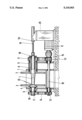
- the drawing shows diagrammatically in axial section a coiling machine for the edge scrap formed in the trimming shearing of steel strips.
- a coiling machine has a conical coiling shaft 1 and two side discs 2, 3 disposed at the ends of the coiling shaft 1.
- the side disc 2 is attached to a flange 4 of a driving shaft 5 mounted rotatably but axially non-displaceably in a bearing block 6.
- the side disc 3 is attached to a flange 7 of a hollow shaft 8 which acts as a driving shaft and is mounted rotatable but axially fixed in a bearing block 9.
- a driving shaft 10 which is disposed parallel with the coiling shaft 1 and which is driven by a driving motor 11 and is drivably connected to the side discs 2, 3 via driving elements, namely driving rollers 12, 13 disposed on the driving shaft 10 and driving belts 14, 15 and driving rollers 16, 17 on the driving shaft 5 and the hollow shaft 8 respectively.
- the conical coiling shaft 1 Via an intermediate member 18 in the hollow shaft 8 the conical coiling shaft 1 is mounted axially displaceably in the hollow shaft 8, a cylinder-and-piston unit 19 retained in an upright 20 acting as an adjusting device, so that the conical coiling shaft 1 can be completely drawn out of the zone between the side discs 2, 3.
- a positive coupling in the form of an adjusting spring is provided between the hollow shaft 8 and the coiling shaft 1.
- the coiling shaft 1 is also entrained.
- the coiling shaft 1 has dogs 22 engaging positively in matching recesses in the flange 4.
Abstract
The invention relates to a coiling machine for strip-shaped material, more particularly for an edged strip formed in the trimming of steel strip. A coiling shaft 1 disposed between two side discs 2, 3 mounted in bearing blocks, 6, 9 is so mounted axially displaceably in a hollow shaft 8 bearing one of the two side discs 3 that the hollow shaft can be drawn out from the zone between the side discs 2, 3. The coiling shaft 1 is also coupled via a more particularly positive coupling 22 for transmitting torque to the directly driven hollow shaft 8. The other side disc 2 is either coupled via driving elements directly to the drive 11 for the hollow shaft 8 or driven by a separate drive.
Description
The invention relates to a coiling machine for strip-shaped material, more particularly for an edge strip formed in the trimming of steel strips, comprising an axially adjustable driven coiling shaft and driven side discs rotatably mounted in lateral bearing blocks, the coiling shaft being mounted axially displaceably in a directly driven axially fixed hollow shaft mounted in one of the lateral bearing blocks and coupled via a more particularly positive coupling for transmitting torque to the hollow shaft that the coiling shaft, so can be drawn out of the zone between the side discs, and the side disc adjacent the hollow shaft being fixed to the hollow shaft.
In a coiling machine of the kind specified known from practice, the side disc remote from the hollow shaft is connected via a positive plug-in coupling to the axially displaceable coiling shaft. Such a coiling machine has the advantage that the coiled edge scrap can be ejected merely by drawing the coiling shaft out of the zone between the side discs, so that no assembly work on the side discs is required. As practical operation has shown, that advantage is offset by the disadvantage that the coupling between the coiling shaft and the side disc remote from the hollow shaft is subject to heavy wear, more particularly because in the case of coiling machines having a large disc diameter the considerable inertial mass of the side disc must be accelerated and braked via the coupling. However, not only the coupling, but the side disc also is itself subject to heavy wear, since after the start of coiling the torque is substantially transmitted between the side disc and the lateral edges of the strip to be coiled. If the coupling is no longer effective, friction occurs between the side disc and the edges of the coiled edge scrap, resulting in wear.
It is an object of the invention to provide a coiling machine of the kind specified in which driving synchronism is permanently ensured between the coiling shaft and the two side discs.
This problem is solved according to the invention by the feature that the other side disc, remote from the hollow shaft, is driven either directly by the drive driving the hollow shaft or by a further drive.
In the coiling machine according to the invention, therefore, the other side disc remote from the hollow shaft is driven directly, and no longer via a coupling between the coiling shaft and the side disc, which at this place cannot be constructed large enough, for reasons of space, to permanently withstand the loadings. It is true that due to the direct drive the cost of manufacture is higher, but in the long run expenditure is nevertheless reduced, since the cost of maintenance is eliminated.
Particularly advantageously in addition a more particularly positive torque-transmitting clutch is provided between the coiling shaft in the operative position and the other side disc. This means that the direct drive can be of comparatively small dimensions. It need merely be designed for the differential torque which in the case of the conventional coupling, provided exclusively between the coiling shaft and the other side disc, led to their premature wear due to overloading, while in the case of two separate drives the direct drive must be designed for speed synchronization.
According to a further feature of the invention the common drive for the hollow shaft and the other side disc has a driving shaft which is disposed parallel with the coiling shaft and is drivably connected via driving elements on the one hand to the hollow shaft and on the other hand to the other side disc.
An embodiment of the invention will now be described in greater detail with reference to the accompanying drawing.
The drawing shows diagrammatically in axial section a coiling machine for the edge scrap formed in the trimming shearing of steel strips.
A coiling machine has a conical coiling shaft 1 and two side discs 2, 3 disposed at the ends of the coiling shaft 1. The side disc 2 is attached to a flange 4 of a driving shaft 5 mounted rotatably but axially non-displaceably in a bearing block 6. The side disc 3 is attached to a flange 7 of a hollow shaft 8 which acts as a driving shaft and is mounted rotatable but axially fixed in a bearing block 9. Mounted in the bearing blocks 6, 9 is a driving shaft 10 which is disposed parallel with the coiling shaft 1 and which is driven by a driving motor 11 and is drivably connected to the side discs 2, 3 via driving elements, namely driving rollers 12, 13 disposed on the driving shaft 10 and driving belts 14, 15 and driving rollers 16, 17 on the driving shaft 5 and the hollow shaft 8 respectively.
Via an intermediate member 18 in the hollow shaft 8 the conical coiling shaft 1 is mounted axially displaceably in the hollow shaft 8, a cylinder-and-piston unit 19 retained in an upright 20 acting as an adjusting device, so that the conical coiling shaft 1 can be completely drawn out of the zone between the side discs 2, 3. A positive coupling in the form of an adjusting spring is provided between the hollow shaft 8 and the coiling shaft 1. When the hollow shaft 8 is driven, therefore, the coiling shaft 1 is also entrained. At its end the coiling shaft 1 has dogs 22 engaging positively in matching recesses in the flange 4. As a result, a torque is transmitted from the drive 11 not only directly via the driving shaft 10 to the side disc 2, but also indirectly via the hollow shaft 8 and the coiling shaft 1 to the side disc 3. This distribution of the torque to be transmitted can be taken into account when dimensioning the two parallel drives, with the object of ensuring that the direct drive via the driving shaft 10 is as small as possible, but that the coupling between the coiling shaft 1 and the side disc 2 is not overloaded.
Claims (3)
1. A coiling machine for strip-shaped material, comprising: lateral bearing blocks, axially fixed side discs rotatably mounted on the bearing blocks; a coiling shaft; an axially fixed hollow shaft mounted in one of the bearing blocks for rotation and connected to one of the side discs for rotation therewith; means mounting the coiling shaft for axial displacement in the hollow shaft between an operative position wherein the coiling shaft is disposed between the two side discs and a second position wherein the coiling shaft is within the hollow shaft and removed from between the two side discs; means for directly driving the hollow shaft; means directly driving the other of the side discs; and means for positively coupling the coiling shaft to the hollow shaft.
2. The coiling machine according to claim 1, further comprising means for positively coupling the coiling shaft to the other of the side discs when the coiling shaft is in the operative position to transmit torque to the other of the side discs via the hollow shaft and the coiling shaft.
3. The coiling machine according to claim 1, wherein the means for directly driving the hollow shaft and the means for directly driving the other of the side discs comprise a common drive with a drive shaft disposed parallel to the coiling shaft and driving elements connecting the drive shaft to the hollow shaft and to the other of the side discs.
Applications Claiming Priority (2)
| Application Number | Priority Date | Filing Date | Title |
|---|---|---|---|
| DE3937992 | 1989-11-15 | ||
| DE3937992A DE3937992C1 (en) | 1989-11-15 | 1989-11-15 |
Publications (1)
| Publication Number | Publication Date |
|---|---|
| US5110063A true US5110063A (en) | 1992-05-05 |
Family
ID=6393586
Family Applications (1)
| Application Number | Title | Priority Date | Filing Date |
|---|---|---|---|
| US07/599,339 Expired - Fee Related US5110063A (en) | 1989-11-15 | 1990-10-17 | Coiling machine for strip-shaped material, more particularly for an edge strip formed in the trimming of steel strips |
Country Status (7)
| Country | Link |
|---|---|
| US (1) | US5110063A (en) |
| EP (1) | EP0431280B1 (en) |
| JP (1) | JPH03184620A (en) |
| AT (1) | ATE89531T1 (en) |
| DE (2) | DE3937992C1 (en) |
| ES (1) | ES2042171T3 (en) |
| RU (1) | RU2050997C1 (en) |
Cited By (12)
| Publication number | Priority date | Publication date | Assignee | Title |
|---|---|---|---|---|
| US5305965A (en) * | 1990-12-21 | 1994-04-26 | Yoshida Kogyo K.K. | Apparatus for winding and storing a tape-like article in a container |
| GB2324079A (en) * | 1995-04-24 | 1998-10-14 | Heidelberger Druckmasch Ag | Web winding |
| US6161604A (en) * | 1995-04-24 | 2000-12-19 | Heidelberger Druckmaschinen Ag | Web-up apparatus and method |
| EP1731458A1 (en) * | 2004-03-10 | 2006-12-13 | Nishimura Seisakusho Co., Ltd. | Winding device |
| CN101181726B (en) * | 2007-12-14 | 2010-06-02 | 中冶南方工程技术有限公司 | Pickling line edge-cut scrap coiling apparatus |
| CN101181725B (en) * | 2007-12-14 | 2010-06-09 | 中冶南方工程技术有限公司 | Waste selvage coiler |
| CN101875455A (en) * | 2010-03-18 | 2010-11-03 | 无锡平盛科技有限公司 | Main spindle part of spool wire-receiving machine |
| CN102390756A (en) * | 2011-06-30 | 2012-03-28 | 河南恒星科技股份有限公司 | Pneumatic tightening device for spool |
| CN102485622A (en) * | 2010-12-02 | 2012-06-06 | 张家港华明机械有限公司 | Winding device |
| CN102500643A (en) * | 2011-09-30 | 2012-06-20 | 山东电力设备有限公司 | Silicon steel rim charge coiling machine |
| CN103071701A (en) * | 2013-02-19 | 2013-05-01 | 中冶赛迪工程技术股份有限公司 | Slitter edge coiling machine |
| CN105984753A (en) * | 2015-02-27 | 2016-10-05 | 上海电缆研究所 | Tape pay-off reel constant tension control device |
Families Citing this family (12)
| Publication number | Priority date | Publication date | Assignee | Title |
|---|---|---|---|---|
| JP5441608B2 (en) * | 2009-10-14 | 2014-03-12 | 日新製鋼株式会社 | Scrap recovery equipment |
| CN102615104B (en) * | 2012-03-30 | 2015-04-08 | 郑州市华驰薄板科技有限公司 | Coiler for trimmings of cold-rolling strip steel |
| DE102013216375A1 (en) | 2013-08-19 | 2015-02-19 | Sms Siemag Ag | Hem winder for band-shaped material |
| RS63452B1 (en) * | 2015-05-05 | 2022-08-31 | Amut Spa | Machine and method for producing bobbins of stretch film |
| CN105692278A (en) * | 2016-03-10 | 2016-06-22 | 四川雅豪房地产开发有限公司 | Production device for building material packaging and bundling steel strips |
| CN105598207A (en) * | 2016-03-17 | 2016-05-25 | 苏州金钜松机电有限公司 | Easily-detachable take-up reel for wire drawer |
| CN105817496A (en) * | 2016-03-17 | 2016-08-03 | 苏州金钜松机电有限公司 | Take-up reel of micro-adjustable wire drawing machine |
| CN106276364A (en) * | 2016-10-19 | 2017-01-04 | 贵州恒瑞辰科技股份有限公司 | A kind of winding shaft drawing mechanism |
| CN106829584A (en) * | 2017-03-21 | 2017-06-13 | 安徽众源新材料股份有限公司 | A kind of copper strips protective layer retracting device and its recycling method |
| CN109719159A (en) * | 2019-01-15 | 2019-05-07 | 吴贝尔 | A kind of cold-strip steel coiler for trimmings with tension coiling |
| CN110125354A (en) * | 2019-05-24 | 2019-08-16 | 天津中晟泰新能源科技有限公司 | A kind of amorphous band spray wrap-up |
| CN110586686A (en) * | 2019-09-23 | 2019-12-20 | 河南明睿达机械制造有限公司 | Unilateral welded tube receives material equipment |
Citations (5)
| Publication number | Priority date | Publication date | Assignee | Title |
|---|---|---|---|---|
| US2066377A (en) * | 1935-10-17 | 1937-01-05 | Wean Engineering Co Inc | Coil holder |
| US2420936A (en) * | 1944-12-06 | 1947-05-20 | Floyd E Davis | Flying coiler |
| US2829845A (en) * | 1955-04-15 | 1958-04-08 | Continental Steel Corp | Coil winding apparatus |
| US3132820A (en) * | 1961-01-13 | 1964-05-12 | Richard F Toll | Bulk roof stock recoiler |
| US4105172A (en) * | 1977-03-11 | 1978-08-08 | Mesta Machine Company | Tension reel for strip coiling |
Family Cites Families (3)
| Publication number | Priority date | Publication date | Assignee | Title |
|---|---|---|---|---|
| US2968448A (en) * | 1957-10-29 | 1961-01-17 | David A Drum | Pinless lap winder |
| GB882728A (en) * | 1958-07-24 | 1961-11-15 | Head Wrightson & Co Ltd | Improvements in scrap metal balling machines |
| DE2844882A1 (en) * | 1978-10-14 | 1980-04-30 | Schloemann Siemag Ag | Seaming strip reeling installation - is fitted with winding prongs made in two sections one of which is driven with other capable of axial movement |
-
1989
- 1989-11-15 DE DE3937992A patent/DE3937992C1/de not_active Expired - Fee Related
-
1990
- 1990-10-09 EP EP90119361A patent/EP0431280B1/en not_active Expired - Lifetime
- 1990-10-09 ES ES199090119361T patent/ES2042171T3/en not_active Expired - Lifetime
- 1990-10-09 DE DE9090119361T patent/DE59001494D1/en not_active Expired - Fee Related
- 1990-10-09 AT AT90119361T patent/ATE89531T1/en not_active IP Right Cessation
- 1990-10-17 US US07/599,339 patent/US5110063A/en not_active Expired - Fee Related
- 1990-11-14 RU SU904831620A patent/RU2050997C1/en active
- 1990-11-14 JP JP2306343A patent/JPH03184620A/en active Pending
Patent Citations (5)
| Publication number | Priority date | Publication date | Assignee | Title |
|---|---|---|---|---|
| US2066377A (en) * | 1935-10-17 | 1937-01-05 | Wean Engineering Co Inc | Coil holder |
| US2420936A (en) * | 1944-12-06 | 1947-05-20 | Floyd E Davis | Flying coiler |
| US2829845A (en) * | 1955-04-15 | 1958-04-08 | Continental Steel Corp | Coil winding apparatus |
| US3132820A (en) * | 1961-01-13 | 1964-05-12 | Richard F Toll | Bulk roof stock recoiler |
| US4105172A (en) * | 1977-03-11 | 1978-08-08 | Mesta Machine Company | Tension reel for strip coiling |
Cited By (19)
| Publication number | Priority date | Publication date | Assignee | Title |
|---|---|---|---|---|
| US5305965A (en) * | 1990-12-21 | 1994-04-26 | Yoshida Kogyo K.K. | Apparatus for winding and storing a tape-like article in a container |
| GB2324079A (en) * | 1995-04-24 | 1998-10-14 | Heidelberger Druckmasch Ag | Web winding |
| GB2324079B (en) * | 1995-04-24 | 1999-03-31 | Heidelberger Druckmasch Ag | Web-fed printing press with web-up apparatus and method |
| US6161604A (en) * | 1995-04-24 | 2000-12-19 | Heidelberger Druckmaschinen Ag | Web-up apparatus and method |
| EP1731458A1 (en) * | 2004-03-10 | 2006-12-13 | Nishimura Seisakusho Co., Ltd. | Winding device |
| EP1731458A4 (en) * | 2004-03-10 | 2007-05-23 | Nishimura Seisakusho Co | Winding device |
| US20080251627A1 (en) * | 2004-03-10 | 2008-10-16 | Masayuki Hatanaka | Winding Apparatus |
| US7694912B2 (en) | 2004-03-10 | 2010-04-13 | Nishimura Seisakustto Co., Ltd. | Winding apparatus |
| CN101181726B (en) * | 2007-12-14 | 2010-06-02 | 中冶南方工程技术有限公司 | Pickling line edge-cut scrap coiling apparatus |
| CN101181725B (en) * | 2007-12-14 | 2010-06-09 | 中冶南方工程技术有限公司 | Waste selvage coiler |
| CN101875455A (en) * | 2010-03-18 | 2010-11-03 | 无锡平盛科技有限公司 | Main spindle part of spool wire-receiving machine |
| CN101875455B (en) * | 2010-03-18 | 2012-07-04 | 无锡平盛科技有限公司 | Main spindle part of spool wire-receiving machine |
| CN102485622A (en) * | 2010-12-02 | 2012-06-06 | 张家港华明机械有限公司 | Winding device |
| CN102390756A (en) * | 2011-06-30 | 2012-03-28 | 河南恒星科技股份有限公司 | Pneumatic tightening device for spool |
| CN102390756B (en) * | 2011-06-30 | 2012-12-19 | 河南恒星科技股份有限公司 | Pneumatic tightening device for spool |
| CN102500643A (en) * | 2011-09-30 | 2012-06-20 | 山东电力设备有限公司 | Silicon steel rim charge coiling machine |
| CN103071701A (en) * | 2013-02-19 | 2013-05-01 | 中冶赛迪工程技术股份有限公司 | Slitter edge coiling machine |
| CN103071701B (en) * | 2013-02-19 | 2015-07-15 | 中冶赛迪工程技术股份有限公司 | Slitter edge coiling machine |
| CN105984753A (en) * | 2015-02-27 | 2016-10-05 | 上海电缆研究所 | Tape pay-off reel constant tension control device |
Also Published As
| Publication number | Publication date |
|---|---|
| EP0431280A1 (en) | 1991-06-12 |
| DE3937992C1 (en) | 1991-02-21 |
| ATE89531T1 (en) | 1993-06-15 |
| EP0431280B1 (en) | 1993-05-19 |
| ES2042171T3 (en) | 1993-12-01 |
| RU2050997C1 (en) | 1995-12-27 |
| JPH03184620A (en) | 1991-08-12 |
| DE59001494D1 (en) | 1993-06-24 |
Similar Documents
| Publication | Publication Date | Title |
|---|---|---|
| US5110063A (en) | Coiling machine for strip-shaped material, more particularly for an edge strip formed in the trimming of steel strips | |
| US4572343A (en) | Electromagnetic friction clutch | |
| EP3479965B1 (en) | Power tool including electromagnetic clutch | |
| US4694944A (en) | Overload clutch particularly for thread-cutting chucks or the like | |
| US5060733A (en) | Power-driven screwing tool | |
| CA2041474A1 (en) | Mower-conditioner drive system | |
| GB2182402A (en) | Fluid friction coupling | |
| CN205278164U (en) | Multi -spring centrifugal clutch | |
| SU502624A1 (en) | Baler safety device | |
| US5787694A (en) | Piston operated collecting machine for agricultural harvested products | |
| CA1163935A (en) | Self-aligning clutch plate drive apparatus | |
| US20050139445A1 (en) | Wedge clutch assembly | |
| US2699850A (en) | Clutch and brake control for reverse gear mechanism | |
| KR20010041977A (en) | Electric steering servo | |
| US6848998B2 (en) | Wedge clutch assembly | |
| SU1094680A1 (en) | Milling cutter arbor | |
| US4934498A (en) | Drive engagement delay device | |
| CN216181755U (en) | Impact drill | |
| SU1043377A1 (en) | Safety device designed mainly for snow blowers | |
| SU821813A1 (en) | Safety clutch | |
| NL1003425C2 (en) | Centrifugal coupling. | |
| JP2559343B2 (en) | Anti-tapping structure of dry multi-plate clutch | |
| SU397366A1 (en) | WORKING ROTOR OF ROTARY MACHINES | |
| JPS5928731Y2 (en) | Running shearing machine | |
| SU390309A1 (en) | Friction clutch |
Legal Events
| Date | Code | Title | Description |
|---|---|---|---|
| AS | Assignment |
Owner name: SUNDWIGER EISENHUTTE MASCHINENFABRIK GRAH & CO., A Free format text: ASSIGNMENT OF ASSIGNORS INTEREST.;ASSIGNOR:KOEPE, WILFRIED;REEL/FRAME:005488/0089 Effective date: 19900921 |
|
| REMI | Maintenance fee reminder mailed | ||
| LAPS | Lapse for failure to pay maintenance fees | ||
| FP | Lapsed due to failure to pay maintenance fee |
Effective date: 19960508 |
|
| FEPP | Fee payment procedure |
Free format text: PAYOR NUMBER ASSIGNED (ORIGINAL EVENT CODE: ASPN); ENTITY STATUS OF PATENT OWNER: SMALL ENTITY |
|
| STCH | Information on status: patent discontinuation |
Free format text: PATENT EXPIRED DUE TO NONPAYMENT OF MAINTENANCE FEES UNDER 37 CFR 1.362 |