EP0428832A1 - Aderverbinder - Google Patents
Aderverbinder Download PDFInfo
- Publication number
- EP0428832A1 EP0428832A1 EP90115668A EP90115668A EP0428832A1 EP 0428832 A1 EP0428832 A1 EP 0428832A1 EP 90115668 A EP90115668 A EP 90115668A EP 90115668 A EP90115668 A EP 90115668A EP 0428832 A1 EP0428832 A1 EP 0428832A1
- Authority
- EP
- European Patent Office
- Prior art keywords
- webs
- guide channels
- side wall
- housing parts
- housing part
- Prior art date
- Legal status (The legal status is an assumption and is not a legal conclusion. Google has not performed a legal analysis and makes no representation as to the accuracy of the status listed.)
- Granted
Links
Images

Classifications
-
- H—ELECTRICITY
- H01—ELECTRIC ELEMENTS
- H01R—ELECTRICALLY-CONDUCTIVE CONNECTIONS; STRUCTURAL ASSOCIATIONS OF A PLURALITY OF MUTUALLY-INSULATED ELECTRICAL CONNECTING ELEMENTS; COUPLING DEVICES; CURRENT COLLECTORS
- H01R4/00—Electrically-conductive connections between two or more conductive members in direct contact, i.e. touching one another; Means for effecting or maintaining such contact; Electrically-conductive connections having two or more spaced connecting locations for conductors and using contact members penetrating insulation
- H01R4/24—Connections using contact members penetrating or cutting insulation or cable strands
- H01R4/2416—Connections using contact members penetrating or cutting insulation or cable strands the contact members having insulation-cutting edges, e.g. of tuning fork type
- H01R4/242—Connections using contact members penetrating or cutting insulation or cable strands the contact members having insulation-cutting edges, e.g. of tuning fork type the contact members being plates having a single slot
- H01R4/2425—Flat plates, e.g. multi-layered flat plates
- H01R4/2429—Flat plates, e.g. multi-layered flat plates mounted in an insulating base
-
- H—ELECTRICITY
- H01—ELECTRIC ELEMENTS
- H01R—ELECTRICALLY-CONDUCTIVE CONNECTIONS; STRUCTURAL ASSOCIATIONS OF A PLURALITY OF MUTUALLY-INSULATED ELECTRICAL CONNECTING ELEMENTS; COUPLING DEVICES; CURRENT COLLECTORS
- H01R4/00—Electrically-conductive connections between two or more conductive members in direct contact, i.e. touching one another; Means for effecting or maintaining such contact; Electrically-conductive connections having two or more spaced connecting locations for conductors and using contact members penetrating insulation
- H01R4/24—Connections using contact members penetrating or cutting insulation or cable strands
- H01R4/2416—Connections using contact members penetrating or cutting insulation or cable strands the contact members having insulation-cutting edges, e.g. of tuning fork type
Definitions
- the invention relates to a wire connector for cable cores, in particular telecommunication cables, according to the preamble of claim 1.
- a wire connector of the generic type is previously known from DE 7 11 675 A1.
- the cable cores of a pair of wires are inserted into the guide channels of the lower housing part and then pressed into the insulation displacement contact elements of the lower housing part by means of the webs of a first upper housing part.
- the cable cores can be cut off using a separating knife arranged in the lower part of the housing.
- the cable cores of a second pair of cables are then inserted into the associated guide channels of the lower housing part and pressed into the insulation displacement contact elements of the lower housing part by means of the webs of a second upper housing part.
- the cable cores can also be cut off by means of separating knives located in the lower housing part.
- the disadvantage here is that different housing parts are required namely the housing lower part forming the guide channels and the insulation displacement contact elements and possibly the separating knife and the two lid-shaped housing upper parts with the webs for pressing the cable cores into the insulation displacement contact elements of the housing lower part.
- the previously known wire connector also has a relatively large volume.
- the invention is therefore based on the object to provide a wire connector of the generic type, which is structurally simpler, so that the manufacturing costs for the housing parts can be reduced, and which also requires only the smallest possible construction volume.
- both housing parts are of identical design and can be locked to one another rotated by 180 °.
- the webs between the guide channels for the cable wires form the press-in webs, wherein when the wire connector is closed, the press-in webs of the one housing part press the cock wires into the insulation displacement contact elements of the other housing part.
- a special cover part as the upper housing part is not required.
- locking element are formed from the side walls of the housing parts running parallel to the guide channels.
- a receiving groove for the other, shorter side wall of the other housing part is provided on the inside of the one side wall of each housing part.
- the wire connector also takes up only a small amount of space, since in the closed state it is cube-shaped.
- the wire connector 1 is used to connect two wire pairs a, b; a1, b1 with each other.
- the wire connector 1 is essentially cube-shaped with an edge length of approx. 10-12 mm. It consists of two identically designed housing parts 2, 2 ', which can be locked against each other by 180 °.
- Each housing part 2.2 ' consists of a bottom, one longer side wall 4, a shorter side wall 5 and two webs 6, 7 arranged parallel to these and firmly connected to the floor 3, which form the insertion webs for the cable cores a, b; a1, b1, as will be described later.
- the two side walls 4, 5 and the two webs 6, 7 run parallel to one another and are each formed in one piece with the base from plastic.
- a first guide channel 8 runs between the two webs 6, 7 and a second guide channel 9 runs between the web 7 and the shorter side wall 5 for the cable cores a, b; a1, b1.
- locking lugs 10 Transverse to the guide channels 8, 9 extend at the height of the upper edges of the webs 6, 7 locking lugs 10, which, starting from the webs 6, 7, are directed towards the opposite web 7 or the opposite shorter side wall 5.
- the locking lugs 10 serve to secure the cable wires a, b; a1, b1 inserted in the guide channels 8, 9 against falling out.
- a receiving groove 11 extends parallel to the longer side wall 4 and the insertion web 6.
- This receiving groove 11 is as long as the shorter side wall 5 and is also open on the side of the bottom 3 to a middle one Bridge part 12. This is opposite a slot 13 which partially divides the shorter side wall 5.
- the shorter side wall 5 has locking lugs 14 on its outside, which are assigned 4 locking lugs 15 on the inside of the longer side wall, which are open towards the receiving groove 11.
- an identically designed further housing part 2 ' can be introduced into the housing part 2 according to FIG. 2 in a position rotated by 180 °, the Shorter side walls 5 of each housing part 2.2 'engage in the receiving grooves 11 of the other housing part 2, 2', since the length of the shorter side wall 5 is the same or slightly shorter than the length of the receiving groove 11.
- the locking lugs 14 slide through it Latch grooves 15 and the slot 13 engages over the bridge 12. In this way, two identically designed housing parts 2.2 'to the cube-shaped wire connector 1 can be locked together.
- each housing part 2.2 insulation displacement contact elements 16 are arranged which cut the guide channels 8.9 at an angle of about 30 ° and which in each guide channel 8.9 a contact slot 17 for the cable wires a, b; Form a1, b1.
- Each insulation displacement contact element 16 is integrally connected at both ends to a buried separating knife 18, a separating knife 18 being arranged at one end of each guide channel 8, 9 and extending transversely to the latter.
- grooves 19 and slots 20 are formed in the insertion webs 6, 7 and in the shorter side wall 5, as shown in FIG. 2.
- cross-slits 21 are also introduced, into which the insulation displacement contact element 16 of the other housing part 2 ′ engage when the wire connector 1 is closed, the insulation displacement contact element 16 of the other housing part 2 ′ after its rotation by 180 ° in mirror image to the insulation displacement contact element 16 of the first housing part 2 is arranged.
- the a and a1 wires are inserted into one housing part 2, the b and b1 wires into the other housing part 2 '.
- the locking lugs 10 bent at short intervals and then form a safeguard against the cable wires falling out.
- the two housing parts 2, 2 'with inserted cable cores a, a1; a, b1 are brought one above the other and the shorter side walls 5 are inserted into the receiving grooves 11.
- the insertion webs 6.7 of one housing part 2 lie above the guide channels 8.9 of the other housing part 2 ', the insertion webs 6.7 in turn lie above the guide channels 8.9 of the other housing part 2.
- FIG. 4 shows a view of the closed wire connector on a scale of 10: 1, the a, b wires of one wire pair a, b being visible. These are held by clamping webs 22 at the ends of the guide channels 8, 9. The locking lugs 10 are pressed against each other and angled.
Abstract
Description
- Die Erfindung bezieht sich auf einen Aderverbinder für Kabeladern, insbesondere von Fernmeldekabeln, gemäß dem Oberbegriff des Anspruches 1.
- Ein Aderverbinder der gattungsgemäßen Art ist aus der DE 7 11 675 A1 vorbekannt. Bei diesem werden die Kabeladern eines Aderpaares in die Führungskanäle des Gehäuseunterteiles eingelegt und anschließend mittels der Stege eines ersten Gehäuseoberteiles in die Schneidklemmkontaktelemente des Gehäuseunterteiles eingedrückt. Dabei kann ein Abschneiden der Kabeladern mittels im Gehäuseunterteil angeordneter Trennmesser erfolgen. Anschließend werden die Kabeladern eines zweiten Kabelpaares in die zugehörigen Führungskanäle des Gehäuseunterteiles eingelegt und mittels der Stege eines zweiten Gehäuseoberteiles in die Schneidklemmkontaktelemente des Gehäuseunterteiles eingedrückt. Hierbei kann ebenfalls ein Abschneiden der Kabeladern durch im Gehäuseunterteil befindliche Trennmesser erfolgen. Nachteilig hierbei ist, daß unterschiedliche Gehäuseteile erforderlich sind, nämlich das die Führungskanäle bildende und die Schneidklemmkontaktelemente und gegebenenfalls die Trennmesser aufnehmende Gehäuseunterteil und die beiden deckelförmigen Gehäuseoberteile mit den Stegen zum Eindrücken der Kabeladern in die Schneidklemmkontaktelemente des Gehäuseunterteiles. Der vorbekannte Aderverbinder hat darüber hinaus ein relativ großes Bauvolumen.
- Der Erfindung liegt von daher die Aufgabe zugrunde, einen Aderverbinder der gattungsgemäßen Art zu schaffen, der konstruktiv einfacher aufgebaut ist, so daß die Herstellungskosten für die Gehäuseteile vermindert werden können, und der darüber hinaus nur ein möglichst geringes Bauvolumen benötigt.
- Die Lösung dieser Aufgabe ergibt sich aus den kennzeichnenden Merkmalen des Anspruches 1. Erfindungsgemäß sind beide Gehäuseteile identisch ausgebildet und um 180° gegeneinander verdreht miteinander verrastbar. Dabei bilden die Stege zwischen den Führungskanälen für die Kabeladern die Eindrückstege, wobei beim Schließen des Aderverbinders die Eindrückstege des einen Gehäuseteiles die Kakeladern in die Schneidklemmkontaktelemente des anderen Gehäuseteiles eindrücken. Ein besonderes Deckelteil als Gehäuseoberteil ist nicht erforderlich. Darüber hinaus sind Rastelement aus den parallel zu den Führungskanälen verlaufenden Seitenwänden der Gehäuseteile ausgebildet. Ferner ist auf der Innenseite der einen Seitenwand eines jeden Gehäuseteiles eine Aufnahmenut für die andere, kürzere Seitenwand der anderen Gehäuseteiles vorgesehen. Durch die identische Ausbildung beider Gehäuseteile, wobei in jedem Gehäuseteil ein Kabeladerpaar aufgenommen wird, die beim Schließen der Aderverbinders sich gegenseitig in die Schneidklemmkontaktelemente eindrücken, wird eine wesentliche konstructive Vereinfachung des erfindungsgemäßen Aderverbinders erzielt, so daß dieser einfach und preiswert herstellbar ist. Auch nimmt der Aderverbinder nur ein geringes Bauvolumen in Anspruch, da dieser in geschlossenem Zustand würfelförmig ist.
- Weitere vorteilhafte Ausgestaltungen der Erfindung ergeben sich aus den Unteransprüchen.
- Die Erfindung ist nachfolgend anhand eines in den Zeichnungen näher dargestellten Ausführungsbeispieles eines Aderverbinders für Kabeladern , insbesondere von Fernmeldekabeln näher erläutert. Es zeigen:
- Fig. 1 die Draufsicht auf den Aderverbinder im Maßstab 1:1 mit zwei angeschlossenen Aderpaaren,
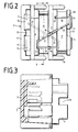
- Fig. 2 die in Maßstab 10:1 vergrößerte Draufsicht auf ein Gehäuseteil,
- Fig. 3 einen Schnitt gemäß der Linie A-B in Fig. 2 durch das Gehäuseteil und
- Fig. 4 eine Stirnansicht im Maßstab 10:1 auf den geschlossenen Aderverbinder.
- Der Aderverbinder 1 dient zur Verbindung zweier Aderpaare a,b; a1,b1 miteinander. Der Aderverbinder 1 ist im wesentlichen Würfelförmig ausgebildet mit einer Kantenlänge von ca.10-12 mm. Er besteht aus zwei identisch ausgebildeten Gehäuseteilen 2, 2′, die um 180° gegeneinander verdreht miteinander verrastbar sind.
- Jedes Gehäuseteil 2,2′ besteht aus einem Boden , einer längeren Seitenwand 4, einer kürzeren Seitenwand 5 und zwei parallel zu diesen angeordneten und mit dem Boden 3 festverbundenen Steg 6,7, welche die Eindrückstege für die Kabeladern a,b;a1,b1 bilden, wie es später noch beschrieben werden wird. Die beiden Seitenwände 4,5 und die beiden Stege 6,7 verlaufen parallel zueinander und sind jeweils mit dem Boden einstückig aus Kunststoff ausgebildet. Zwischen den beiden Stegen 6,7 verläuft ein erster Führungskanal 8 und zwischen dem Steg 7 und der kürzeren Seitenwand 5 verläuft ein zweiter Führungskanal 9 für die Kabeladern a,b;a1,b1. Quer zu den Führungskanälen 8,9 erstrecken sich in der Höhe der Oberkanten der Stege 6,7 Sperrnasen 10, die jweils von den Stegen 6,7 ausgehend in Richtung auf den gegenüberliegenden Steg 7 bzw. die gegenüberliegenden kürzere Seitenwand 5 gerichtet sind. Die Sperrnasen 10 dienen zur Sicherung der in die Führungskanäle 8,9 eingelegten Kabeladern a,b;a1,b1, gegen ein Herausfallen.
- Zwischen der längeren Seitenwand 4 und dem ersten Eindrücksteg 6 erstreckt sich eine Aufnahmenut 11 parallel zur längeren Seitenwand 4 und zum Eindrücksteg 6. Diese Aufnahmenut 11 ist so lang wie die kürzere Seitenwand 5 und ist auch auf der Seite des Bodens 3 offen biz auf einen mittleren Brückenteil 12. Diesem liegt ein Schlitz 13 gegenüber, welcher die kürzere Seitenwand 5 partiell unterteilt. Die kürzere Seitenwand 5 besitzt auf ihrer Außenseite Rastnasen 14, denen auf der Innenseite der längeren Seitenwand 4 Rastnasennuten 15 zugeordnet sind, die zur Aufnahmenut 11 hin geöffnet sind.
- Wie es anhand der Fig. 2 und anhand voranstehender Beschreibung ersichtlich ist, kann in das Gehäuseteil 2 gemäß Fig. 2 ein identisch ausgebildetes weiteres Gehäuseteil 2′ in um 180° verdrehter Lage eingebracht werden, wobei die kürzeren Seitenwände 5 eines jeden Gehäuseteiles 2,2′ in die Aufnahmenuten 11 des jeweils anderen Gehäuseteiles 2, 2′ eingreifen, da die Länge der kürzeren Seitenwand 5 gleich oder etwas kürzer ist als die Länge der Aufnahmenut 11. Die Rastnasen 14 gleiten dabei durch die Rastnasennuten 15 und der Schlitz 13 greift über die Brücke 12. Auf diese Weise können zwei identisch ausgebildete Gehäuseteile 2,2′ zum würfelförmigen Aderverbinder 1 miteinander verrastet werden.
- In den Führungskanälen 8,9 eines jeden Gehäuseteiles 2,2′ sind Schneidklemmkontaktelemente 16 angeordnet, welche die Führungskanäle 8,9 unter einem Winkel von etwa 30° schneiden und welche in jedem Führungskanal 8,9 einen Kontaktschlitz 17 für die Kabeladern a,b;a1,b1 ausbilden. Jedes Schneidklemmkontaktelement 16 ist an beiden Enden einstückig mit einem abgeborgenen Trennmesser 18 verbunden, wobei jeweils ein Trennmesser 18 an einem Ende eines jeden Führungskanales 8,9 angeordnet ist und quer zu diesem verläuft. Zur Aufnahme und Fixierung der Schneidklemmkontaktelement 16 und der zugehörigen Trennmesser 18 sind in den Eindrückstegen 6,7 und in der kürzeren Seitenwand 5 Nuten 19 und Schlitze 20 ausgebildet, wie es in Fig. 2 dargestellt ist. In den Eindrückstegen 6,7 sind darüber hinaus Querschlitze 21 eingebracht, in welche das Schneidklemmkontaktelement 16 des anderen Gehäuseteiles 2′ bei dem Schließen des Aderverbinders 1 eingreifen, wobei das Schneidklemmkontaktelement 16 des anderen Gehäuseteiles 2′ nach dessen Drehung um 180° spiegelbildlich zum Schneidklemmkontaktelement 16 des ersten Gehäuseteiles 2 angeordnet ist.
- Zum Verbinden zweier Aderpaare, a,b;a1,b1 werden die a und a1 Adern in ein Gehäuseteil 2,die b und b1 Adern in das andere Gehäuseteil 2′ eingelegt. Hierbei werden die Sperrnasen 10 kruzzeitig verbogen und bilden anschließend eine Sicherung gegen ein Herausfallen der Kabeladern. Anschließend werden die beiden Gehäuseteile 2,2′ mit eingelegten Kabeladern a, a1;a,b1 übereinander gebracht und die Kürzeren Seitenwände 5 in die Aufnahmenuten 11 eingeführt. Dabei leigen die Eindrückstege 6,7 des einen Gehäuseteiles 2 oberhalb der Führungskanäle 8,9 des anderen Gehäuseteiles 2′, dessen Eindrückstege 6,7 wiederum oberhalb der Führungskanäle 8,9 des anderen Gehäuseteiles 2 liegen. Beim Zusammendrücken der beiden Gehäuseteile 2,2′ drücken dann die Eindrückstege 6,7 eines jeden Gehäuseteiles 2,2′ die Kabeladern a,a1 bzw. b,b1 in die Führungskanäle 8,9 des jeweils anderen Gehäuseteiles 2,2′ ein, wodurch die beiden Paare von Kabeladern a,a1 und b,b1 miteinander über die Schneidklemmkontaktelemente 16 elektrisch leitend verbunden werden, die aus metallisch leitfähigem Material bestehen. Die Rastnasen 14 einer jeden kürzeren Seitenwand 5 rasten am Ende der Rastnasennuten 15 der längeren Seitenwand 4 ein, so daß der Aderverbinder 1 verrastet und hermetisch verschlossen ist. Zur Sicherung der Kontaktverbindungen gegen Feuchtigkeit kann vor dem Verschließen Fett in den Innenraum der Gehäuseteile 2,2′ eingebracht werden.
- Die Fig. 4 zeigt eine Ansicht des geschlossenen Aderverbinders im Maßstab 10:1, wobei die a,b Adern des einen Aderpaares a,b ersichtlich sind. Diese werden durch Klemmstege 22 an den Enden der Führungskanäle 8,9 gehalten. Die Sperrnasen 10 sind gegeneinander gedrückt und abgewinkelt.
Claims (5)
dadurch gekennzeichnet,
daß beide Gehäuseteile (2,2′) identisch ausgebildet und um 180° gegeneinander verdreht miteinander verrastbar sind, daß die Stege (6,7) zwischen den Führungskanälen (8,9) die Eindrückstege bilden, daß die Rastelemente aus den parallel zu den Führungskanälen (8,9) verlaufenden Seitenwänden (4,5) der Gehäuseteile (2,2′) ausgebildet sind und daß auf der Innenseite der längeren Gehäusewand (4) eine Aufnahmenut (11) für die andere, kürzere Seitenwand (5) der Gehäuseteile (2,2′) ausgebildet ist.
Priority Applications (1)
| Application Number | Priority Date | Filing Date | Title |
|---|---|---|---|
| AT90115668T ATE100242T1 (de) | 1989-11-15 | 1990-08-16 | Aderverbinder. |
Applications Claiming Priority (2)
| Application Number | Priority Date | Filing Date | Title |
|---|---|---|---|
| DE3938365 | 1989-11-15 | ||
| DE3938365A DE3938365C1 (de) | 1989-11-15 | 1989-11-15 |
Publications (2)
| Publication Number | Publication Date |
|---|---|
| EP0428832A1 true EP0428832A1 (de) | 1991-05-29 |
| EP0428832B1 EP0428832B1 (de) | 1994-01-12 |
Family
ID=6393791
Family Applications (1)
| Application Number | Title | Priority Date | Filing Date |
|---|---|---|---|
| EP90115668A Expired - Lifetime EP0428832B1 (de) | 1989-11-15 | 1990-08-16 | Aderverbinder |
Country Status (15)
| Country | Link |
|---|---|
| US (1) | US5192223A (de) |
| EP (1) | EP0428832B1 (de) |
| JP (1) | JPH03182066A (de) |
| KR (1) | KR910010773A (de) |
| CN (1) | CN1028693C (de) |
| AT (1) | ATE100242T1 (de) |
| AU (1) | AU648988B2 (de) |
| BR (1) | BR9005277A (de) |
| DE (2) | DE3938365C1 (de) |
| DK (1) | DK0428832T3 (de) |
| ES (1) | ES2050316T3 (de) |
| MX (1) | MX171746B (de) |
| RU (1) | RU2024132C1 (de) |
| TR (1) | TR26608A (de) |
| UA (1) | UA11071A (de) |
Families Citing this family (4)
| Publication number | Priority date | Publication date | Assignee | Title |
|---|---|---|---|---|
| DE4331212C2 (de) * | 1993-09-10 | 1997-04-30 | Krone Ag | Klemmanschlußeinheit |
| US5487184A (en) * | 1993-11-09 | 1996-01-23 | Motorola, Inc. | Offset transmission line coupler for radio frequency signal amplifiers |
| CN114976684B (zh) * | 2022-06-17 | 2023-06-20 | 浙江久盛交联电缆有限公司 | 一种铁路机车车辆受流器用电缆组件 |
| CN115084882B (zh) * | 2022-07-19 | 2022-11-25 | 江西京九电源科技有限公司 | 一种蓄电池的电连接铜端子构件 |
Citations (4)
| Publication number | Priority date | Publication date | Assignee | Title |
|---|---|---|---|---|
| DE2648820A1 (de) * | 1976-10-27 | 1978-05-03 | Siemens Ag | Steckvorrichtung |
| CH640982A5 (en) * | 1979-01-04 | 1984-01-31 | Ove Johansson | Electrical connecting device |
| CH645480A5 (de) * | 1977-11-10 | 1984-09-28 | Minnesota Mining & Mfg | Loetloser elektrischer steckverbinder. |
| US4842546A (en) * | 1987-05-25 | 1989-06-27 | Song Won J | Covered wire connecting device for power source connecting plug |
Family Cites Families (6)
| Publication number | Priority date | Publication date | Assignee | Title |
|---|---|---|---|---|
| US3233206A (en) * | 1963-05-31 | 1966-02-01 | Joseph N Sicuro | Electrical connector |
| US3576518A (en) * | 1968-11-07 | 1971-04-27 | Minnesota Mining & Mfg | Solderless connector for insulated wires |
| US3804971A (en) * | 1971-06-28 | 1974-04-16 | Minnesota Mining & Mfg | Solderless wire connector |
| US3899236A (en) * | 1974-06-24 | 1975-08-12 | Amerace Corp | Electrical connector |
| AR208483A1 (es) * | 1975-11-10 | 1976-12-27 | Amp Inc | Terminal electrico |
| DE3711675A1 (de) * | 1987-04-07 | 1988-10-27 | Krone Ag | Aderverbinder fuer kabeladern, insbesondere von fernmeldekabeln |
-
1989
- 1989-11-15 DE DE3938365A patent/DE3938365C1/de not_active Expired - Lifetime
-
1990
- 1990-08-16 DE DE90115668T patent/DE59004220D1/de not_active Expired - Fee Related
- 1990-08-16 DK DK90115668.7T patent/DK0428832T3/da active
- 1990-08-16 EP EP90115668A patent/EP0428832B1/de not_active Expired - Lifetime
- 1990-08-16 ES ES90115668T patent/ES2050316T3/es not_active Expired - Lifetime
- 1990-08-16 AT AT90115668T patent/ATE100242T1/de not_active IP Right Cessation
- 1990-08-28 MX MX022135A patent/MX171746B/es unknown
- 1990-08-31 AU AU62063/90A patent/AU648988B2/en not_active Ceased
- 1990-09-14 KR KR1019900014531A patent/KR910010773A/ko active IP Right Grant
- 1990-10-19 BR BR909005277A patent/BR9005277A/pt not_active Application Discontinuation
- 1990-10-30 US US07/605,952 patent/US5192223A/en not_active Expired - Fee Related
- 1990-11-08 JP JP2301239A patent/JPH03182066A/ja active Pending
- 1990-11-14 RU SU904831554A patent/RU2024132C1/ru active
- 1990-11-14 UA UA4831554A patent/UA11071A/uk unknown
- 1990-11-14 TR TR90/1068A patent/TR26608A/xx unknown
- 1990-11-15 CN CN90109274A patent/CN1028693C/zh not_active Expired - Fee Related
Patent Citations (4)
| Publication number | Priority date | Publication date | Assignee | Title |
|---|---|---|---|---|
| DE2648820A1 (de) * | 1976-10-27 | 1978-05-03 | Siemens Ag | Steckvorrichtung |
| CH645480A5 (de) * | 1977-11-10 | 1984-09-28 | Minnesota Mining & Mfg | Loetloser elektrischer steckverbinder. |
| CH640982A5 (en) * | 1979-01-04 | 1984-01-31 | Ove Johansson | Electrical connecting device |
| US4842546A (en) * | 1987-05-25 | 1989-06-27 | Song Won J | Covered wire connecting device for power source connecting plug |
Also Published As
| Publication number | Publication date |
|---|---|
| US5192223A (en) | 1993-03-09 |
| EP0428832B1 (de) | 1994-01-12 |
| ATE100242T1 (de) | 1994-01-15 |
| CN1061493A (zh) | 1992-05-27 |
| AU648988B2 (en) | 1994-05-12 |
| JPH03182066A (ja) | 1991-08-08 |
| BR9005277A (pt) | 1991-09-17 |
| UA11071A (uk) | 1996-12-25 |
| MX171746B (es) | 1993-11-10 |
| DE3938365C1 (de) | 1991-07-11 |
| ES2050316T3 (es) | 1994-05-16 |
| KR910010773A (ko) | 1991-06-29 |
| DE59004220D1 (de) | 1994-02-24 |
| DK0428832T3 (da) | 1994-02-21 |
| RU2024132C1 (ru) | 1994-11-30 |
| AU6206390A (en) | 1991-05-23 |
| CN1028693C (zh) | 1995-05-31 |
| TR26608A (tr) | 1995-03-15 |
Similar Documents
| Publication | Publication Date | Title |
|---|---|---|
| EP0637097B1 (de) | Anschlussleiste für hohe Übertragungsraten in der Telekommunikations- und Datentechnik | |
| EP0595234B1 (de) | Kabelstecker für vieladrige Kabel | |
| DE3711675C2 (de) | ||
| DE3807645C2 (de) | Steckverbindungssystem für elektrische Leiter | |
| DE4433983A1 (de) | Anschlußklemme für elektrische Installationen | |
| DE2849419C2 (de) | ||
| EP0959529B1 (de) | Elektrische Anschlussbaueinheit | |
| DE2941029A1 (de) | Zum einpressverbinden mit einem elektrischen leiter vorgesehenen elektrischen anschlussteil, verfahren zum verbinden eines anschlussteils mit einem elektrischen leiter sowie verbinder mit einer mehrzahl elektrischer anschlussteile | |
| DE3009675C2 (de) | ||
| DE4334615C1 (de) | Elektrischer Steckverbinder | |
| EP0382322A1 (de) | Anschlussleiste | |
| DE10057833B4 (de) | Steckverbinder für mehradrige Daten- und/oder Telekommunikations-Kabel | |
| DE10223271B4 (de) | Steckverbinder | |
| DE4431274A1 (de) | Verfahren zum Herstellen eines Elektro-Installationsgerätes sowie Elektro-Installationsgerät | |
| EP0428832B1 (de) | Aderverbinder | |
| DE19945412A1 (de) | Elektrischer Kontakt und elektrischer Steckverbinder mit einem solchen Kontakt | |
| DE2714158C3 (de) | Anschlußvorrichtung für ein vieladriges Rundkabel | |
| EP0063696A1 (de) | Steckereinsatzelemente für Flachschnüre | |
| DE2232311C2 (de) | Lötfreier Drahtverbinder | |
| DE3503412A1 (de) | Verbinder zum anschliessen eines mehradrigen elektrichen flachkabels an andere schaltungselemente | |
| DE4446807C2 (de) | Steckverbindergehäuse | |
| DE4345247C2 (de) | Schneidklemm-Verbindungsstecker | |
| DE2525221A1 (de) | Elektrische reihenverbindungsanordnung | |
| DE4238923C2 (de) | Stecker | |
| EP0901186A2 (de) | Anschlusselement für Schirmkabel |
Legal Events
| Date | Code | Title | Description |
|---|---|---|---|
| PUAI | Public reference made under article 153(3) epc to a published international application that has entered the european phase |
Free format text: ORIGINAL CODE: 0009012 |
|
| 17P | Request for examination filed |
Effective date: 19910228 |
|
| AK | Designated contracting states |
Kind code of ref document: A1 Designated state(s): AT BE CH DE DK ES FR GB GR IT LI LU NL SE |
|
| 17Q | First examination report despatched |
Effective date: 19930615 |
|
| GRAA | (expected) grant |
Free format text: ORIGINAL CODE: 0009210 |
|
| AK | Designated contracting states |
Kind code of ref document: B1 Designated state(s): AT BE CH DE DK ES FR GB GR IT LI LU NL SE |
|
| REF | Corresponds to: |
Ref document number: 100242 Country of ref document: AT Date of ref document: 19940115 Kind code of ref document: T |
|
| ITF | It: translation for a ep patent filed |
Owner name: JACOBACCI CASETTA & PERANI S.P.A. |
|
| GBT | Gb: translation of ep patent filed (gb section 77(6)(a)/1977) |
Effective date: 19940118 |
|
| REG | Reference to a national code |
Ref country code: DK Ref legal event code: T3 |
|
| REF | Corresponds to: |
Ref document number: 59004220 Country of ref document: DE Date of ref document: 19940224 |
|
| ET | Fr: translation filed | ||
| REG | Reference to a national code |
Ref country code: GR Ref legal event code: FG4A Free format text: 3010448 |
|
| REG | Reference to a national code |
Ref country code: ES Ref legal event code: FG2A Ref document number: 2050316 Country of ref document: ES Kind code of ref document: T3 |
|
| PG25 | Lapsed in a contracting state [announced via postgrant information from national office to epo] |
Ref country code: LU Free format text: LAPSE BECAUSE OF NON-PAYMENT OF DUE FEES Effective date: 19940831 Ref country code: LI Effective date: 19940831 Ref country code: CH Effective date: 19940831 |
|
| PLBE | No opposition filed within time limit |
Free format text: ORIGINAL CODE: 0009261 |
|
| STAA | Information on the status of an ep patent application or granted ep patent |
Free format text: STATUS: NO OPPOSITION FILED WITHIN TIME LIMIT |
|
| 26N | No opposition filed | ||
| EAL | Se: european patent in force in sweden |
Ref document number: 90115668.7 |
|
| REG | Reference to a national code |
Ref country code: CH Ref legal event code: PL |
|
| PGFP | Annual fee paid to national office [announced via postgrant information from national office to epo] |
Ref country code: GB Payment date: 19960729 Year of fee payment: 7 |
|
| PGFP | Annual fee paid to national office [announced via postgrant information from national office to epo] |
Ref country code: DE Payment date: 19960813 Year of fee payment: 7 |
|
| PGFP | Annual fee paid to national office [announced via postgrant information from national office to epo] |
Ref country code: FR Payment date: 19960814 Year of fee payment: 7 |
|
| PGFP | Annual fee paid to national office [announced via postgrant information from national office to epo] |
Ref country code: AT Payment date: 19960820 Year of fee payment: 7 |
|
| PGFP | Annual fee paid to national office [announced via postgrant information from national office to epo] |
Ref country code: SE Payment date: 19960822 Year of fee payment: 7 Ref country code: NL Payment date: 19960822 Year of fee payment: 7 Ref country code: BE Payment date: 19960822 Year of fee payment: 7 |
|
| PGFP | Annual fee paid to national office [announced via postgrant information from national office to epo] |
Ref country code: DK Payment date: 19960823 Year of fee payment: 7 |
|
| PGFP | Annual fee paid to national office [announced via postgrant information from national office to epo] |
Ref country code: GR Payment date: 19960829 Year of fee payment: 7 |
|
| PGFP | Annual fee paid to national office [announced via postgrant information from national office to epo] |
Ref country code: ES Payment date: 19960830 Year of fee payment: 7 |
|
| PG25 | Lapsed in a contracting state [announced via postgrant information from national office to epo] |
Ref country code: GB Free format text: LAPSE BECAUSE OF NON-PAYMENT OF DUE FEES Effective date: 19970816 Ref country code: DK Free format text: LAPSE BECAUSE OF NON-PAYMENT OF DUE FEES Effective date: 19970816 Ref country code: AT Free format text: LAPSE BECAUSE OF NON-PAYMENT OF DUE FEES Effective date: 19970816 |
|
| REG | Reference to a national code |
Ref country code: DK Ref legal event code: EBP |
|
| PG25 | Lapsed in a contracting state [announced via postgrant information from national office to epo] |
Ref country code: SE Free format text: LAPSE BECAUSE OF NON-PAYMENT OF DUE FEES Effective date: 19970817 |
|
| PG25 | Lapsed in a contracting state [announced via postgrant information from national office to epo] |
Ref country code: ES Free format text: LAPSE BECAUSE OF THE APPLICANT RENOUNCES Effective date: 19970818 |
|
| PG25 | Lapsed in a contracting state [announced via postgrant information from national office to epo] |
Ref country code: GR Free format text: LAPSE BECAUSE OF NON-PAYMENT OF DUE FEES Effective date: 19970831 Ref country code: BE Free format text: LAPSE BECAUSE OF NON-PAYMENT OF DUE FEES Effective date: 19970831 |
|
| BERE | Be: lapsed |
Owner name: KRONE A.G. Effective date: 19970831 |
|
| PG25 | Lapsed in a contracting state [announced via postgrant information from national office to epo] |
Ref country code: NL Free format text: LAPSE BECAUSE OF NON-PAYMENT OF DUE FEES Effective date: 19980301 |
|
| GBPC | Gb: european patent ceased through non-payment of renewal fee |
Effective date: 19970816 |
|
| PG25 | Lapsed in a contracting state [announced via postgrant information from national office to epo] |
Ref country code: FR Free format text: LAPSE BECAUSE OF NON-PAYMENT OF DUE FEES Effective date: 19980430 |
|
| PG25 | Lapsed in a contracting state [announced via postgrant information from national office to epo] |
Ref country code: DE Free format text: LAPSE BECAUSE OF NON-PAYMENT OF DUE FEES Effective date: 19980501 |
|
| EUG | Se: european patent has lapsed |
Ref document number: 90115668.7 |
|
| NLV4 | Nl: lapsed or anulled due to non-payment of the annual fee |
Effective date: 19980301 |
|
| REG | Reference to a national code |
Ref country code: FR Ref legal event code: ST |
|
| REG | Reference to a national code |
Ref country code: ES Ref legal event code: FD2A Effective date: 20001102 |
|
| PG25 | Lapsed in a contracting state [announced via postgrant information from national office to epo] |
Ref country code: IT Free format text: LAPSE BECAUSE OF NON-PAYMENT OF DUE FEES;WARNING: LAPSES OF ITALIAN PATENTS WITH EFFECTIVE DATE BEFORE 2007 MAY HAVE OCCURRED AT ANY TIME BEFORE 2007. THE CORRECT EFFECTIVE DATE MAY BE DIFFERENT FROM THE ONE RECORDED. Effective date: 20050816 |