EP0428029A2 - Serrure - Google Patents
Serrure Download PDFInfo
- Publication number
- EP0428029A2 EP0428029A2 EP19900121089 EP90121089A EP0428029A2 EP 0428029 A2 EP0428029 A2 EP 0428029A2 EP 19900121089 EP19900121089 EP 19900121089 EP 90121089 A EP90121089 A EP 90121089A EP 0428029 A2 EP0428029 A2 EP 0428029A2
- Authority
- EP
- European Patent Office
- Prior art keywords
- key
- locking device
- tumblers
- tumbler
- teeth
- Prior art date
- Legal status (The legal status is an assumption and is not a legal conclusion. Google has not performed a legal analysis and makes no representation as to the accuracy of the status listed.)
- Granted
Links
Images


Classifications
-
- E—FIXED CONSTRUCTIONS
- E05—LOCKS; KEYS; WINDOW OR DOOR FITTINGS; SAFES
- E05B—LOCKS; ACCESSORIES THEREFOR; HANDCUFFS
- E05B19/00—Keys; Accessories therefor
-
- E—FIXED CONSTRUCTIONS
- E05—LOCKS; KEYS; WINDOW OR DOOR FITTINGS; SAFES
- E05B—LOCKS; ACCESSORIES THEREFOR; HANDCUFFS
- E05B19/00—Keys; Accessories therefor
- E05B19/26—Use of special materials for keys
-
- E—FIXED CONSTRUCTIONS
- E05—LOCKS; KEYS; WINDOW OR DOOR FITTINGS; SAFES
- E05B—LOCKS; ACCESSORIES THEREFOR; HANDCUFFS
- E05B29/00—Cylinder locks and other locks with plate tumblers which are set by pushing the key in
- E05B29/0013—Cylinder locks and other locks with plate tumblers which are set by pushing the key in with rotating plate tumblers
- E05B29/002—Cylinder locks and other locks with plate tumblers which are set by pushing the key in with rotating plate tumblers rotating about an axis perpendicular to the key axis
-
- E—FIXED CONSTRUCTIONS
- E05—LOCKS; KEYS; WINDOW OR DOOR FITTINGS; SAFES
- E05B—LOCKS; ACCESSORIES THEREFOR; HANDCUFFS
- E05B35/00—Locks for use with special keys or a plurality of keys ; keys therefor
- E05B35/006—Locks for use with special keys or a plurality of keys ; keys therefor for rack- or pinion-like keys
-
- Y—GENERAL TAGGING OF NEW TECHNOLOGICAL DEVELOPMENTS; GENERAL TAGGING OF CROSS-SECTIONAL TECHNOLOGIES SPANNING OVER SEVERAL SECTIONS OF THE IPC; TECHNICAL SUBJECTS COVERED BY FORMER USPC CROSS-REFERENCE ART COLLECTIONS [XRACs] AND DIGESTS
- Y10—TECHNICAL SUBJECTS COVERED BY FORMER USPC
- Y10T—TECHNICAL SUBJECTS COVERED BY FORMER US CLASSIFICATION
- Y10T70/00—Locks
- Y10T70/70—Operating mechanism
- Y10T70/7441—Key
- Y10T70/7486—Single key
- Y10T70/7508—Tumbler type
- Y10T70/7559—Cylinder type
- Y10T70/7588—Rotary plug
- Y10T70/7627—Rotary or swinging tumblers
- Y10T70/7633—Transverse of plug
-
- Y—GENERAL TAGGING OF NEW TECHNOLOGICAL DEVELOPMENTS; GENERAL TAGGING OF CROSS-SECTIONAL TECHNOLOGIES SPANNING OVER SEVERAL SECTIONS OF THE IPC; TECHNICAL SUBJECTS COVERED BY FORMER USPC CROSS-REFERENCE ART COLLECTIONS [XRACs] AND DIGESTS
- Y10—TECHNICAL SUBJECTS COVERED BY FORMER USPC
- Y10T—TECHNICAL SUBJECTS COVERED BY FORMER US CLASSIFICATION
- Y10T70/00—Locks
- Y10T70/70—Operating mechanism
- Y10T70/7441—Key
- Y10T70/7768—Key-removal preventing
-
- Y—GENERAL TAGGING OF NEW TECHNOLOGICAL DEVELOPMENTS; GENERAL TAGGING OF CROSS-SECTIONAL TECHNOLOGIES SPANNING OVER SEVERAL SECTIONS OF THE IPC; TECHNICAL SUBJECTS COVERED BY FORMER USPC CROSS-REFERENCE ART COLLECTIONS [XRACs] AND DIGESTS
- Y10—TECHNICAL SUBJECTS COVERED BY FORMER USPC
- Y10T—TECHNICAL SUBJECTS COVERED BY FORMER US CLASSIFICATION
- Y10T70/00—Locks
- Y10T70/70—Operating mechanism
- Y10T70/7441—Key
- Y10T70/778—Operating elements
- Y10T70/7791—Keys
- Y10T70/7802—Multi-part structures
Definitions
- the invention relates in particular to a locking device intended for motor vehicles with a locking cylinder and a key, the locking cylinder comprising at least one cylinder housing with at least one locking channel and a cylinder core with tumblers.
- Locking devices of the type mentioned are known in a wide variety of embodiments and are installed in doors, flaps and steering columns of motor vehicles. Furthermore, these locking devices are also used in many other cases.
- the invention has for its object to design a locking device of the type mentioned in such a way that new and previously unknown locking options result.
- the invention provides that the tumblers are each movable about an axis and that at least one protruding driver or a recess for transmitting the straight-line key movement into a movement of the tumblers about their respective axes are provided on the key or on the tumbler side.
- the tumblers are thus not movable in a straight line to the key channel, but are pivotable and engage in the blocking position with at least one nose located on their circumference in the blocking channel or lie with their nose outside the blocking channel, so that the cylinder core is freely rotatable.
- the tumblers are controlled using the key via recesses and shift teeth or control teeth, which allows the design of new types of keys and thus offers a wide variety of variations.
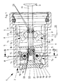
- a locking device 1 according to FIG. 1, which is particularly intended for use in motor vehicles, comprises a locking cylinder 2 and a key 3.
- the locking cylinder 2 includes a cylinder housing 4 with locking channels 5 and a cylinder core 6 with tumblers 7a, 7b, 7c and 7d .
- the tumblers 7a to 7d are each mounted in the cylinder core 6 so as to be movable about an axis 8. Furthermore, at least one protruding driver 9 or a recess 10 is provided on the key 3 or on each of the tumblers 7a to 7d for transmitting the straight-line key movement into a movement of the tumblers 7a to 7d about its axis 8.
- the protruding driver 9 is located on the key 3 or on the key shaft 11 thereof, while a recess 10 is arranged on each of the tumblers 7a to 7d.
- a recess 10 is arranged on each of the tumblers 7a to 7d.
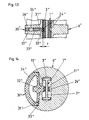
- two switching teeth 12 are provided on the circumference 13 of each tumbler 7a to 7d, as can be seen above all from the illustration on an even larger scale in FIG. 4.
- the tumblers 7a to 7d also have at least one nose 14 or 15 which can be pivoted into the blocking channel 5 on their circumference 13 (FIG. 4). These lugs 14, 15 are arranged diametrically opposite the recess 10 or the shift teeth 12.
- the tumblers 7a to 7d can be pivoted about the axes 8 and cannot be freely rotated. Furthermore, the tumblers 7a to 7d are acted upon by a torsion spring 16 (FIG. 4), which presses the tumblers into the blocking position, so that the tumblers must be pivoted against the spring force from the blocking position into the release position with the aid of the key 3.
- a torsion spring 16 FIG. 4
- the cylinder core 6 has pockets 17 which are open radially outwards and serve to receive the tumblers 7a to 7d.
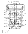
- the tumblers 7a to 7d are pivotally mounted in the pockets 17 and, in the locked position according to FIG. 1, only reach out of the pockets 17 with their lugs 15. 2, the tumblers 7a to 7d lie with their noses 14 and 15 in the pockets 17 and take one with the circumference 18 of the Cylinder core 6 flush position.
- Tumblers 7a to 7d and pockets 17 are thus provided in more than one plane 19, 20, preferably four tumblers 7a to 7d lying in a total of two radial planes 19, 20.
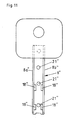
- the key 3 has a single projecting driver 9 in the form of a control tooth 9.
- this control tooth 9 engages the switching teeth 12 of the tumblers 7a to 7d or runs into the recess 10 between the two switching teeth 12 and adjusts the tumblers during the linear movement up to a stop 22 7a to 7d and brings them into their release position according to FIG. 2.
- the situation shortly before the control teeth 9 enter the key 3 into the recesses 10 of the tumblers 7a to 7d is shown in FIG. 1, taking into account the permutation options and the variety of variations, the four control teeth 9 can be arranged in different key levels 23.
- the recesses 10 and the switching teeth 12 are always provided on the circumference 13 of the tumblers 7a to 7d in principle at the same point.
- the lugs 14 and 15, on the other hand, are arranged on the tumblers 7a to 7d in the case of different tumblers 7a to 7d and, owing to the possibility of permutation among one another and to the shift teeth 12.
- Each tumbler 7a to 7d has two lugs 14 and 15 in the illustrated embodiment. Not only a single locking lug is provided, so that even if the wrong key is used or if e.g. the tumblers are pivoted with the aid of a toothed rack, the second tooth still closes when the first tooth is in a release position.
- the axes 8 for the tumblers 7a to 7d are located on inserts 24 which can be inserted into corresponding recesses 25 in the cylinder core 6.
- the insert 24 is at least partially of the same contour as the cylinder core 6, the free ends of the axes 8 also lying in cylindrical through openings 26 of the cylinder core 6 according to the exemplary embodiment.
- the tumblers 7a to 7d can have recesses 10 or switching teeth 12 in more than one plane 27 (for a non-reversing key).
- Recesses 10 and shift teeth 12 are preferably located in two levels 27 (FIG. 3), and accordingly control teeth 9 are arranged on more than one level 27 on the key 3 for such tumblers.
- each tumbler has only a single recess 10 and correspondingly two switching teeth 12.
- Fig. 5 shows a modified embodiment or of this only a broken piece of the cylinder core 6 with the tumbler channel 21 and the pocket 17, in which a tumbler 7b 'is pivotally mounted on the axis 8. From the key 3 'is also only the key tip 28 adjacent end shown in Fig. 5.
- the tumbler 7b ' at least one protruding over its circumference 13 driver 9' in the form of control teeth 9 'and the key 3' each one Driver 9 'of the tumbler 7b' associated recess 10 '.
- the above driver 9 ' is therefore not on the key 3', but on the tumbler 7b 'and accordingly the recess 10' is no longer arranged on the tumbler 7b ', but on the key 3'.
- the recess 10 ' has a relatively large, free length. This is necessary because a second driver 9 'according to the embodiment must lie in this recess 10 when the tumbler 7b' is in the release position.
- the key shaft 3 ⁇ comprises a cross-sectionally double-T-shaped carrier 6 ⁇ according to FIG. 11, which consists of a web 7 ⁇ and four legs 8a ⁇ , 8b ⁇ , 8c ⁇ and 8d ⁇ . Furthermore, a plastic cover 9schaft is used to form the key shaft 3 ⁇ according to FIGS. 6 to 10, which is preferably arranged on both sides of the web 7 ⁇ and between the legs 8a ⁇ and 8b ⁇ or 8c ⁇ and 8d ⁇ (FIG. 7 ).
- the double-T-shaped carrier 6 ⁇ is a metallic core with sufficient strength, which is at least partially covered by the plastic cover 9 ⁇ forming the control elements 5 ⁇ .
- the plastic coating extends at the handle-side end of the key shaft 3 ⁇ from one leg 8a ⁇ to the other leg 8b ⁇ and then merges into a central web 13 ⁇ due to lateral recesses 10 ⁇ , 11 Mittel and 12 ⁇ , the free end 14 ⁇ of which the key tip 4 ⁇ extends and then, for example, on the other side of the key shaft continues with a reversible key in a corresponding center bar with side recesses.
- control elements 5 ⁇ are elevations made of plastic and thus control teeth. They are perpendicular to the flat side 15 ⁇ of the key shaft 3 ⁇ and are also preferably integrally connected to the central web 13 ⁇ or the plastic cover 9 ⁇ . Also, the control teeth 5 ⁇ are preferably sunk in the flat side 15 ⁇ of the key shaft 3 vers, as FIGS. 8 and 10 show.
- each flat side 15 réelle of the key shaft 3 ⁇ can have two rows 16 ⁇ and 17 ⁇ with control teeth 5 ⁇ , these then directly next to the legs 8a ⁇ to 8d ⁇ of the key shaft 3 ⁇ or respectively between the central web 13 ⁇ and the legs 8a ⁇ to 8d ⁇ are arranged.
- the double-T-shaped carrier 6 ⁇ in its web 7 ⁇ in the area of the control teeth 5 ⁇ has passage openings 18 ⁇ , as shown in FIGS. 9 and 11 emerges.
- the plastic cover 9 ⁇ completely fills the passage openings 18 ⁇ (FIG. 9) and thereby also connects the plastic cover parts 19 ⁇ and 20 ⁇ located on the two sides of the web 7 ⁇ (FIG. 9).
- the control teeth 5 ⁇ rise above the plastic located in the passage openings 18 ⁇ and are integrally connected to the central web 13 ⁇ or the central webs 13 ⁇ on both sides of the key 1 ⁇ .
- the passage openings 18 ⁇ are elongated holes and extend in the longitudinal direction of the key shaft.
- the length of the passage openings 18 ⁇ is much larger than the width of the control teeth 5 ⁇ in the direction of the key shaft 3 ⁇ .
- the control teeth 5 ⁇ can therefore be arranged at various points in the area of the passage openings 18 ⁇ . Finally, this is also desirable because of the permutation options required.
- the key shaft 3 ⁇ has only two control teeth 5 ⁇ in each row of teeth 16 ⁇ or 17 ⁇ . They are arranged at a large distance from one another and can be positioned according to the size of the passage openings 18 ⁇ (Fig. 11) vary or be more or less apart. However, their position is always defined by the position of the passage openings 18 ⁇ .
- the plastic cover 9 ⁇ or its double-sided plastic cover parts 19 ⁇ and 20 ⁇ fill the space between the web 7 ⁇ and the legs 8a ⁇ to 8d ⁇ in such a way that the plastic cover 9 ⁇ and the free end of the control teeth 5 ⁇ do not have that Project level of the lateral edge surfaces 23 ⁇ of the legs 8a ⁇ to 8d ⁇ .
- the plastic middle web 13 ⁇ has a groove-shaped depression 24 ⁇ . It extends transversely to the longitudinal direction of the key shaft 3 ⁇ and thus parallel to the flanks of the control teeth 5 ⁇ .
- the groove-shaped recess 24 ⁇ serves to fix the key shaft to a locking element 30 ⁇ of the cylinder lock (FIGS. 13 and 14).
- the exemplary embodiment shown in FIG. 12 is a slightly modified key 1a ⁇ , in which matching parts have the same reference numbers, but with a letter index.
- the key 1a ⁇ also has a key handle 2a ⁇ and a key shaft 3a ⁇ , which, however, as a control element does not have control teeth, but recesses 5a ⁇ and / or through openings 5a ⁇ in the key shaft 3a ⁇ . These recesses and / or through openings 5a ⁇ can be arranged in a cross-sectionally double-T-shaped carrier 6a ⁇ , which consists only of metal and / or plastic or a plastic coating 9a ⁇ .
- the key 1 ⁇ with control teeth 5 ⁇ is used primarily in connection with a cylinder lock, which has tumblers pivotally mounted about an axis.
- the control teeth engage in recesses on the tumblers.
- the other key 1a ⁇ with recesses 5a ⁇ and / or through openings 5a ⁇ is also used in connection with a pivotally mounted tumbler cylinder lock, but the tumblers do not have recesses as control elements, but are provided with teeth or the like for this purpose.
- the mode of operation and function of both cylinder locks is the same.
- a major advantage of the key 1 ⁇ or 1a ⁇ is that the control elements 5 ⁇ or 5a ⁇ on the key shaft 3 ⁇ or 3a ⁇ can be sprayed from plastic onto a metallic profile.
- the control teeth 5 ⁇ are therefore no longer produced by mechanical processing such as by milling, but by precise injection molding onto a rail-shaped metal profile, which expediently has passage openings for anchoring the control teeth.
- the production of the key can be highly automated and electronically controlled.
- the latching element 30 comprises a spring web 31 which is arranged in a freely resilient manner and which carries a latching lug 32.
- the detent 32 ⁇ protrudes on the key side beyond the spring bar 31 ⁇ and is able to bridge a spring travel f according to FIG. 13 in order to move out of the detent position into a release position when the key 1 ⁇ is removed.
- the latching element 30 ⁇ preferably lies continuously with its circumference in a recess 33 ⁇ of the cylinder core 6 and has a recess 34 ⁇ behind the spring bar 32 ⁇ in order to achieve the spring property.
- the recess 33 ⁇ in the cylinder core 6 extends with a passage opening 35 ⁇ for the locking lug 32 ⁇ into the key channel and is limited by two wall elements 36 ⁇ and 37 ⁇ according to FIG. 13 for mounting the locking element 3o 3.
Applications Claiming Priority (4)
| Application Number | Priority Date | Filing Date | Title |
|---|---|---|---|
| DE19893937611 DE3937611A1 (de) | 1989-11-11 | 1989-11-11 | Schliesseinrichtung |
| DE3937611 | 1989-11-11 | ||
| DE4019943 | 1990-06-22 | ||
| DE19904019943 DE4019943A1 (de) | 1990-06-22 | 1990-06-22 | Schluessel |
Related Child Applications (1)
| Application Number | Title | Priority Date | Filing Date |
|---|---|---|---|
| EP93105625.3 Division-Into | 1990-11-03 |
Publications (3)
| Publication Number | Publication Date |
|---|---|
| EP0428029A2 true EP0428029A2 (fr) | 1991-05-22 |
| EP0428029A3 EP0428029A3 (en) | 1992-03-04 |
| EP0428029B1 EP0428029B1 (fr) | 1996-01-10 |
Family
ID=25886985
Family Applications (2)
| Application Number | Title | Priority Date | Filing Date |
|---|---|---|---|
| EP19900121089 Expired - Lifetime EP0428029B1 (fr) | 1989-11-11 | 1990-11-03 | Serrure |
| EP19930105625 Withdrawn EP0567808A1 (fr) | 1989-11-11 | 1990-11-03 | Clé |
Family Applications After (1)
| Application Number | Title | Priority Date | Filing Date |
|---|---|---|---|
| EP19930105625 Withdrawn EP0567808A1 (fr) | 1989-11-11 | 1990-11-03 | Clé |
Country Status (4)
| Country | Link |
|---|---|
| US (1) | US5189895A (fr) |
| EP (2) | EP0428029B1 (fr) |
| DE (1) | DE59010048D1 (fr) |
| ES (1) | ES2081898T3 (fr) |
Cited By (1)
| Publication number | Priority date | Publication date | Assignee | Title |
|---|---|---|---|---|
| WO2000000711A1 (fr) * | 1998-06-30 | 2000-01-06 | Medeco Security Locks, Inc. | Cles a surface structuree ameliorees et serrures a barillet pour cles a surface structuree |
Families Citing this family (4)
| Publication number | Priority date | Publication date | Assignee | Title |
|---|---|---|---|---|
| DE19908085C1 (de) * | 1999-02-25 | 2000-06-21 | Huf Huelsbeck & Fuerst Gmbh | Vorrichtung zur Aufnahme und Halterung eines Identifikationsgebers, wie eines elektronischen Schlüssels, insbesondere für einen Zündanlaßschalter und/oder eine Lenksäuleneverriegelung eines Motorfahrzeugs |
| DE19927500A1 (de) * | 1999-06-16 | 2000-12-21 | Volkswagen Ag | Türschloß, insbesondere für ein Kraftfahrzeug |
| US7318332B1 (en) * | 2006-08-04 | 2008-01-15 | Jin Tay Industries Co., Ltd. | Lock |
| US20140216114A1 (en) * | 2013-02-07 | 2014-08-07 | Schlage Lock Company Llc | Lockdown cylinder locks |
Citations (8)
| Publication number | Priority date | Publication date | Assignee | Title |
|---|---|---|---|---|
| FR410647A (fr) * | 1909-12-22 | 1910-05-25 | Pierre Duret | Canon de sureté pour serrures |
| US1594297A (en) * | 1922-01-13 | 1926-07-27 | Rosa S Muzzio | Cylinder lock |
| CH132552A (de) * | 1929-02-20 | 1929-04-30 | Luethi Anton | Sicherheitstürschloss. |
| DE643259C (de) * | 1934-07-05 | 1937-04-03 | Simon Futran | Zylinderschloss |
| DE2731138A1 (de) * | 1977-07-09 | 1979-01-25 | Huwil Werke Gmbh | Sicherheits-schliessystem |
| DE3005481A1 (de) * | 1979-03-02 | 1980-09-11 | Grundmann Gmbh Geb | Zylinderschloss und schluessel |
| EP0140740A1 (fr) * | 1983-09-16 | 1985-05-08 | FICHET-BAUCHE SociétÀ© dite: | Serrure de sûreté |
| EP0192467A1 (fr) * | 1985-02-19 | 1986-08-27 | Sinesio Barquin Ochoa | Engrenage à crémaillère activant des unités d'une serrure cylindrique |
Family Cites Families (19)
| Publication number | Priority date | Publication date | Assignee | Title |
|---|---|---|---|---|
| US1317828A (en) * | 1919-10-07 | Thb couimbta pljlhoogapk co | ||
| US1193412A (en) * | 1916-08-01 | nelson | ||
| US834918A (en) * | 1906-01-23 | 1906-11-06 | Paul K Lindgren | Cylinder-lock and key therefor. |
| FI43046B (fr) * | 1964-10-07 | 1970-09-02 | Forsman H | |
| US3404548A (en) * | 1966-06-29 | 1968-10-08 | Owen F. Keefer | Lock |
| US3509748A (en) * | 1968-04-24 | 1970-05-05 | Fort Lock Corp | Axial pin tumbler lock |
| US4069695A (en) * | 1972-12-29 | 1978-01-24 | Roger Frank | Bar-tumbler type safety lock |
| FR2231240A6 (fr) * | 1973-05-22 | 1974-12-20 | Neiman Exploitation Brevets | |
| FR2297976A1 (fr) * | 1975-01-17 | 1976-08-13 | Fichet Bauche | Serrure de surete |
| AT371532B (de) * | 1978-12-15 | 1983-07-11 | Grundmann Gmbh Geb | Flachschluessel |
| FR2501827A1 (fr) * | 1981-03-16 | 1982-09-17 | Roustan Marguerite | Cle a systeme mecanique pour mecanismes de securite |
| ES270406Y (es) * | 1983-02-17 | 1984-02-16 | Llave de combinacion. | |
| AT380513B (de) * | 1984-03-07 | 1986-06-10 | Grundmann Gmbh Geb | Schluessel-schlosskombination |
| US4662200A (en) * | 1984-10-15 | 1987-05-05 | Borda Rafael U | Combination key |
| DE3503660A1 (de) * | 1985-02-04 | 1986-08-07 | Fa. Wilhelm Karrenberg, 5620 Velbert | Schliessvorrichtung mit schliesszylinder und flachschluessel |
| JPS6428078A (en) * | 1987-07-20 | 1989-01-30 | Iseki Agricult Mach | Transmission device for traveling of moving agricultural machine |
| US5029459A (en) * | 1987-09-03 | 1991-07-09 | Mitsubishi Corporation | Flat plastic key with rigid torque transfer insert |
| US4941336A (en) * | 1988-03-09 | 1990-07-17 | Steckler Edward T | Lock mechanism |
| US4953420A (en) * | 1989-09-29 | 1990-09-04 | Clum Manufacturing Company, Inc. | Key lock apparatus |
-
1990
- 1990-11-02 US US07/608,305 patent/US5189895A/en not_active Expired - Fee Related
- 1990-11-03 EP EP19900121089 patent/EP0428029B1/fr not_active Expired - Lifetime
- 1990-11-03 DE DE59010048T patent/DE59010048D1/de not_active Expired - Fee Related
- 1990-11-03 EP EP19930105625 patent/EP0567808A1/fr not_active Withdrawn
- 1990-11-03 ES ES90121089T patent/ES2081898T3/es not_active Expired - Lifetime
Patent Citations (8)
| Publication number | Priority date | Publication date | Assignee | Title |
|---|---|---|---|---|
| FR410647A (fr) * | 1909-12-22 | 1910-05-25 | Pierre Duret | Canon de sureté pour serrures |
| US1594297A (en) * | 1922-01-13 | 1926-07-27 | Rosa S Muzzio | Cylinder lock |
| CH132552A (de) * | 1929-02-20 | 1929-04-30 | Luethi Anton | Sicherheitstürschloss. |
| DE643259C (de) * | 1934-07-05 | 1937-04-03 | Simon Futran | Zylinderschloss |
| DE2731138A1 (de) * | 1977-07-09 | 1979-01-25 | Huwil Werke Gmbh | Sicherheits-schliessystem |
| DE3005481A1 (de) * | 1979-03-02 | 1980-09-11 | Grundmann Gmbh Geb | Zylinderschloss und schluessel |
| EP0140740A1 (fr) * | 1983-09-16 | 1985-05-08 | FICHET-BAUCHE SociétÀ© dite: | Serrure de sûreté |
| EP0192467A1 (fr) * | 1985-02-19 | 1986-08-27 | Sinesio Barquin Ochoa | Engrenage à crémaillère activant des unités d'une serrure cylindrique |
Cited By (2)
| Publication number | Priority date | Publication date | Assignee | Title |
|---|---|---|---|---|
| WO2000000711A1 (fr) * | 1998-06-30 | 2000-01-06 | Medeco Security Locks, Inc. | Cles a surface structuree ameliorees et serrures a barillet pour cles a surface structuree |
| US6105404A (en) * | 1998-06-30 | 2000-08-22 | Medeco Security Locks, Inc. | Squiggle keys and cylinder locks for squiggle keys |
Also Published As
| Publication number | Publication date |
|---|---|
| EP0428029B1 (fr) | 1996-01-10 |
| EP0428029A3 (en) | 1992-03-04 |
| DE59010048D1 (de) | 1996-02-22 |
| EP0567808A1 (fr) | 1993-11-03 |
| ES2081898T3 (es) | 1996-03-16 |
| US5189895A (en) | 1993-03-02 |
Similar Documents
| Publication | Publication Date | Title |
|---|---|---|
| EP1290303B1 (fr) | Serrure a barres pour systeme de fermeture | |
| EP1700979B1 (fr) | Fenêtre coulissante mobile, notamment d'un véhicule | |
| DE102012101117B4 (de) | Stangenschloss mit zusätzlicher Stangenstabilisierung | |
| EP0428029A2 (fr) | Serrure | |
| DE3036262C2 (de) | Schließeinrichtung | |
| AT407272B (de) | Flachschlüssel für zylinderschlösser | |
| DE3134471C2 (fr) | ||
| DE10122637A1 (de) | Dichtungsanordnung für ein Kraftfahrzeugfenster | |
| EP0668428A1 (fr) | Arrêt de porte | |
| DE2144756B2 (de) | Fernbetatigungsvornchtung, ins besondere fur Kraftfahrzeugturschlosser | |
| DE3937611A1 (de) | Schliesseinrichtung | |
| DE3305209C2 (fr) | ||
| WO2009068333A1 (fr) | Mécanisme de commande de crémone | |
| DE10005136A1 (de) | Schließzylinder, insbesondere für Kfz | |
| DE2535455C3 (de) | Rastschloß | |
| DE2759925C2 (de) | Verriegelungsvorrichtung für Fenster, Türen od.dgl. | |
| DE2823102C2 (de) | Einrichtung zur Betätigung eines Steuerschiebers, insbesondere für ein Mehrstellungs-Mehrwegeventil | |
| CH658337A5 (en) | Locking mechanism | |
| DE2613605B2 (de) | Zylinderschloß | |
| DE60012064T2 (de) | Treibstangenverschlüsse | |
| DE2745747B2 (de) | Zylinderkern mit Wendeschlüssel für ein Zylinderschloß | |
| DE8525568U1 (de) | Schere, insbesondere Gartenschere | |
| DE19801681A1 (de) | Schließvorrichtung für Dachkoffer von Kraftfahrzeugen | |
| EP1611652B1 (fr) | Element de verrouillage pour fixer un appareil d'installation pour des barres omnibus | |
| DE2152199A1 (de) | Tuerschloss mit einem verriegelungsund klinkenmechanismus |
Legal Events
| Date | Code | Title | Description |
|---|---|---|---|
| PUAI | Public reference made under article 153(3) epc to a published international application that has entered the european phase |
Free format text: ORIGINAL CODE: 0009012 |
|
| AK | Designated contracting states |
Kind code of ref document: A2 Designated state(s): DE ES FR GB IT SE |
|
| PUAL | Search report despatched |
Free format text: ORIGINAL CODE: 0009013 |
|
| AK | Designated contracting states |
Kind code of ref document: A3 Designated state(s): DE ES FR GB IT SE |
|
| 17P | Request for examination filed |
Effective date: 19920401 |
|
| 17Q | First examination report despatched |
Effective date: 19921002 |
|
| GRAA | (expected) grant |
Free format text: ORIGINAL CODE: 0009210 |
|
| AK | Designated contracting states |
Kind code of ref document: B1 Designated state(s): DE ES FR GB IT SE |
|
| REF | Corresponds to: |
Ref document number: 59010048 Country of ref document: DE Date of ref document: 19960222 |
|
| ET | Fr: translation filed | ||
| REG | Reference to a national code |
Ref country code: ES Ref legal event code: FG2A Ref document number: 2081898 Country of ref document: ES Kind code of ref document: T3 |
|
| GBT | Gb: translation of ep patent filed (gb section 77(6)(a)/1977) |
Effective date: 19960219 |
|
| ITF | It: translation for a ep patent filed |
Owner name: STUDIO JAUMANN |
|
| PLBE | No opposition filed within time limit |
Free format text: ORIGINAL CODE: 0009261 |
|
| STAA | Information on the status of an ep patent application or granted ep patent |
Free format text: STATUS: NO OPPOSITION FILED WITHIN TIME LIMIT |
|
| 26N | No opposition filed | ||
| PGFP | Annual fee paid to national office [announced via postgrant information from national office to epo] |
Ref country code: SE Payment date: 20011018 Year of fee payment: 12 |
|
| PGFP | Annual fee paid to national office [announced via postgrant information from national office to epo] |
Ref country code: GB Payment date: 20011026 Year of fee payment: 12 |
|
| PGFP | Annual fee paid to national office [announced via postgrant information from national office to epo] |
Ref country code: DE Payment date: 20011115 Year of fee payment: 12 |
|
| PGFP | Annual fee paid to national office [announced via postgrant information from national office to epo] |
Ref country code: ES Payment date: 20011116 Year of fee payment: 12 |
|
| PGFP | Annual fee paid to national office [announced via postgrant information from national office to epo] |
Ref country code: FR Payment date: 20011130 Year of fee payment: 12 |
|
| REG | Reference to a national code |
Ref country code: GB Ref legal event code: IF02 |
|
| PG25 | Lapsed in a contracting state [announced via postgrant information from national office to epo] |
Ref country code: GB Free format text: LAPSE BECAUSE OF NON-PAYMENT OF DUE FEES Effective date: 20021103 |
|
| PG25 | Lapsed in a contracting state [announced via postgrant information from national office to epo] |
Ref country code: SE Free format text: LAPSE BECAUSE OF NON-PAYMENT OF DUE FEES Effective date: 20021104 Ref country code: ES Free format text: LAPSE BECAUSE OF NON-PAYMENT OF DUE FEES Effective date: 20021104 |
|
| PG25 | Lapsed in a contracting state [announced via postgrant information from national office to epo] |
Ref country code: DE Free format text: LAPSE BECAUSE OF NON-PAYMENT OF DUE FEES Effective date: 20030603 |
|
| GBPC | Gb: european patent ceased through non-payment of renewal fee | ||
| EUG | Se: european patent has lapsed | ||
| PG25 | Lapsed in a contracting state [announced via postgrant information from national office to epo] |
Ref country code: FR Free format text: LAPSE BECAUSE OF NON-PAYMENT OF DUE FEES Effective date: 20030731 |
|
| REG | Reference to a national code |
Ref country code: FR Ref legal event code: ST |
|
| REG | Reference to a national code |
Ref country code: ES Ref legal event code: FD2A Effective date: 20031213 |
|
| PG25 | Lapsed in a contracting state [announced via postgrant information from national office to epo] |
Ref country code: IT Free format text: LAPSE BECAUSE OF NON-PAYMENT OF DUE FEES;WARNING: LAPSES OF ITALIAN PATENTS WITH EFFECTIVE DATE BEFORE 2007 MAY HAVE OCCURRED AT ANY TIME BEFORE 2007. THE CORRECT EFFECTIVE DATE MAY BE DIFFERENT FROM THE ONE RECORDED. Effective date: 20051103 |