EP0427097A1 - Drosselklappe für eine Brennkraftmaschine - Google Patents
Drosselklappe für eine Brennkraftmaschine Download PDFInfo
- Publication number
- EP0427097A1 EP0427097A1 EP90120854A EP90120854A EP0427097A1 EP 0427097 A1 EP0427097 A1 EP 0427097A1 EP 90120854 A EP90120854 A EP 90120854A EP 90120854 A EP90120854 A EP 90120854A EP 0427097 A1 EP0427097 A1 EP 0427097A1
- Authority
- EP
- European Patent Office
- Prior art keywords
- throttle valve
- shaft
- servomotor
- valve according
- cable
- Prior art date
- Legal status (The legal status is an assumption and is not a legal conclusion. Google has not performed a legal analysis and makes no representation as to the accuracy of the status listed.)
- Granted
Links
- 238000002485 combustion reaction Methods 0.000 title claims abstract description 5
- 230000008878 coupling Effects 0.000 claims abstract description 48
- 238000010168 coupling process Methods 0.000 claims abstract description 48
- 238000005859 coupling reaction Methods 0.000 claims abstract description 48
- 238000011084 recovery Methods 0.000 abstract 1
- 230000007257 malfunction Effects 0.000 description 3
- 230000015572 biosynthetic process Effects 0.000 description 1
- 230000000903 blocking effect Effects 0.000 description 1
- 230000001627 detrimental effect Effects 0.000 description 1
- 238000000034 method Methods 0.000 description 1
- 230000001105 regulatory effect Effects 0.000 description 1
Images


Classifications
-
- F—MECHANICAL ENGINEERING; LIGHTING; HEATING; WEAPONS; BLASTING
- F02—COMBUSTION ENGINES; HOT-GAS OR COMBUSTION-PRODUCT ENGINE PLANTS
- F02D—CONTROLLING COMBUSTION ENGINES
- F02D11/00—Arrangements for, or adaptations to, non-automatic engine control initiation means, e.g. operator initiated
- F02D11/06—Arrangements for, or adaptations to, non-automatic engine control initiation means, e.g. operator initiated characterised by non-mechanical control linkages, e.g. fluid control linkages or by control linkages with power drive or assistance
- F02D11/10—Arrangements for, or adaptations to, non-automatic engine control initiation means, e.g. operator initiated characterised by non-mechanical control linkages, e.g. fluid control linkages or by control linkages with power drive or assistance of the electric type
- F02D11/107—Safety-related aspects
Definitions
- the invention relates to a throttle valve for an internal combustion engine, which is mounted on a shaft, with a cable pull through which the shaft can be rotated, at least one return spring on the cable pull, a first stop between the cable pull and the shaft, a first coupling device between the cable pull and the shaft and a servomotor.
- a throttle valve of this type is known from German published patent application DE-OS 37 11 779.
- the throttle valve is mounted on a shaft that can be turned by a cable. A force is applied to the cable pull by a return spring in the closing direction of the throttle valve.
- the throttle valve also has a first stop between the cable pull and the shaft, the stop point of which is shifted with the aid of the cable pull, the throttle valve being movable between its closed position and the stop position.
- a coupling device is arranged between the cable and the shaft, which is designed here as a spring.
- the throttle valve has a servomotor which can actuate the throttle valve.
- the servomotor is connected to the shaft via a second stop, the attachment point of which can be advanced using the servomotor, so that the throttle valve can be actuated in the closing direction.
- the servomotor is not automatically tracked when the throttle valve is actuated by the cable, so that when the servomotor intervenes in the throttle valve position, there is an undesirable delay which is detrimental to the control behavior, e.g. B. a traction control system for a motor vehicle.
- the invention has for its object to provide a throttle valve, which increases the safety and reliability in the operation of the motor vehicle with a simple and inexpensive design and relieves the servomotor during its operation from a large force which restores the throttle valve.
- the first coupling device is a first coupling which has a changing or cancelable frictional connection, the frictional connection being greatest in the immediate area of the variable attachment point.
- the first coupling device is a first clutch, which has a changing or cancelable frictional engagement, the frictional engagement being greatest in the immediate area of the variable attachment point, because when the throttle valve is operated by the servomotor, the Actuator only has to apply small forces to adjust the throttle valve, which means that the servomotor can be designed in a particularly simple and cost-effective manner as a servomotor with a low output and, in addition, due to the relief of the servomotor from a large force that restores the throttle valve, reliability and safety the operation of the motor vehicle is increased because the service life of the servomotor is increased.
- the second coupling device consists of a spring which is arranged between the servomotor and the shaft, since this results in a particularly simple and inexpensive embodiment which has a particularly high level of reliability.
- the second coupling device is a second clutch, which has a changing or cancelable frictional connection, because on the one hand a particularly reliable tracking of the servomotor is ensured when the throttle valve is actuated by the cable and on the other hand it is ensured that, for . B. a blocking of the servomotor Movement of the throttle valve is ensured by the cable.
- first and / or second coupling is each designed as a latching sliding connection, there is the advantage that for a predetermined position of the shaft to the cable pull or the servomotor, a fixed coupling between the shaft and the cable pull or the shaft and the servomotor is ensured and that for the further positions of the shaft to the cable pull and the shaft to the servomotor only a small force is required to twist the shaft by the cable pull or the servomotor.
- the locking slide connection consists of a two-armed omega-shaped spring and at least two locking recesses on one of the shafts results in the advantage of a particularly simple and inexpensive design of the locking sliding connections, which have a high degree of reliability.
- first and / or second clutch is a pneumatically or electrically or hydraulically actuatable clutch, because it ensures a particularly reliable coupling and releasing of the cable to the throttle valve and / or the servomotor to the throttle valve, thereby ensuring safety and the reliability in the operation of the motor vehicle is considerably increased without the costs for the throttle valve becoming too high.
- the cable pull is assigned a setpoint potentiometer, whereby the setpoint position of the throttle valve can be determined in a simple and inexpensive manner.
- a diagnostic device is connected to the actual value potentiometer and the setpoint potentiometer, as a result of which incorrect settings of the throttle valve and / or the servomotor and / or the first or second coupling device can be detected easily and reliably, error messages can be output and an emergency operation circuit can be activated, which increases the reliability and safety in the operation of the motor vehicle.
- a speed controller actuation device is connected to the cable, because a speed controller can thus be connected to the throttle valve in a simple and inexpensive manner, and thus the motor vehicle, in addition to the actuation of the throttle valve by a cable that is coupled to an accelerator pedal, also actuates is made possible by a speed controller, with the servo motor, for example, also in the operation of the throttle valve by the speed controller.
- B. is fully available for a traction control function.
- the fact that the actuating device is connected to the sheave via a third coupling device, which is a spring or a clutch with variable or removable force fit, has the advantage that the speed controller can be coupled to the throttle valve in a particularly simple and reliable manner, as a result of which there is a high level of security in the operation of the motor vehicle.
- the cruise control actuator can thus an operation of the throttle valve by the cable can be tracked at any time of the movement of the cable, which results in the advantage when the speed controller requires intervention that it can adjust the throttle valve without delay.
- a third stop is arranged between the actuating device and the cable, because this ensures that when the throttle valve is operated by the speed controller, a secure connection between the speed controller and the shaft for an adjustment of the throttle valve in Direction is made open, at the same time resetting the speed controller actuation device is ensured by the return spring, which results in a particularly high level of safety when operating the motor vehicle.
- the cable is advantageous for the cable to be coupled to a cable pulley, which results in a particularly simple and inexpensive articulation of the cable.
- a second stop is arranged between the shaft and the servomotor, thereby ensuring that when the throttle valve is operated by the servomotor, the servomotor can be actuated in the direction of closing without delay and with a high degree of certainty.
- Figure 1 shows a first embodiment of the throttle valve according to the invention using a system drawing.
- the throttle valve (D) is mounted on a shaft (W) that can be rotated by the cable (S).
- the cable pull (S) is connected here as an example for a particularly simple articulation with a cable pulley (SB).
- the rope pulley (SB) is acted upon by at least one return spring (R) with force in the closing direction of the throttle valve (D).
- the rope pulley (SB) is mounted on a shaft (X), which is also connected to a setpoint potentiometer (SP) and adjusts this when the rope pulley (SB) and the cable pull (S) are actuated, so that a control device or a Diagnostic device, which are not shown here, a setpoint signal for the position of the throttle valve (D) can be supplied.
- a first part of a first stop (A1) is also mounted on the shaft (X), the stop point of which can be shifted by the cable (S), the throttle valve (D) being movable between its closed position and the stop position.
- a first coupling device (K1) is arranged between the first part and the second part of the stop (A1), which is a first coupling (K1) and one has a changing or cancelable adhesion, the adhesion being greatest in the immediate area of the variable attachment point.
- the second part of the stop (A1) is firmly connected to the shaft (W).
- the throttle valve (D) also has a servomotor (M) which is mounted on a shaft (Y) and which adjusts the throttle valve (D) via the shaft (W) as a function of predetermined or calculated control variables.
- M servomotor
- the servomotor (M) To determine the actual position, the position of the servomotor (M) and the position of the throttle valve (D), the servomotor (M) is assigned an actual value potentiometer (IP).
- a second coupling device (K2) is arranged between the shaft (W) and the shaft (Y) and thus the servomotor (M), which connects or can positively connect the servomotor (M) to the shaft (W).
- the cable pulley (SB) is connected via a third coupling device (K3), which can be designed as a spring or a clutch with variable or removable force-locking , connected or connectable to the cruise control actuator (GR).
- the speed controller actuation device (GR) is connected to the rope pulley (SB) via a third stop (A3), which on the one hand ensures that when the throttle valve (D) is actuated by the speed controller due to the coupling by the third coupling device (K3) the speed controller can be engaged without delay and the speed controller actuating device (GR) is acted upon by the return spring (R) with force in the closing direction of the throttle valve (D).
- first and second coupling devices K1, K2
- the embodiments described below result, for example.
- the first coupling device (K1) shown in FIG. B. be designed as an electrical or pneumatic or hydraulic clutch (K1), which is controlled as a function of the signals from the actual value potentiometer (IP) and the setpoint potentiometer (SP) by a control device or diagnostic device, not shown. If the first and the second part of the first stop are at the stop point, the first clutch (K1) is closed. As soon as actuation of the throttle valve by the servomotor (M) is required, the first clutch (K1) is opened to relieve the servomotor (M), so that it can be designed as a simple servomotor with low power, so that overall results in an inexpensive design.
- a second coupling device (K2) is arranged between the shaft (Y) and the shaft (W), which is designed as a second clutch (K2) can be, which can have a changing or cancelable frictional connection.
- the second clutch (K2) can also be designed as an electrical or pneumatic or hydraulically actuated clutch (K2), which is controlled by a control device or diagnostic device, not shown. It is advantageous that the second clutch (K2) is closed except in the event of a malfunction of the servomotor (M), so that the servomotor (M) follows the rotary movement of the shaft (W) at all times and if the servomotor (M ) This ensures that the servomotor (M) can adjust the shaft (W) without delay. In the event that a The servomotor (M) is malfunctioning or an emergency operation function has to be switched, the second clutch (K2) can be opened so that the throttle valve (D) can be freely adjusted using the cable (S).
- first and / or second clutch (K1, K2) is designed as an electrically or pneumatically or hydraulically actuable clutch (K1, K2), there is the particular advantage of very high reliability in operation and a very high degree of adaptability to the required control processes , which are controlled by the control device, not shown, which nevertheless results in an inexpensive design.
- the exemplary embodiment shown in FIG. 2 differs from the exemplary embodiment shown in FIG. 1 only in another embodiment of the second coupling device (K2).
- the second coupling device (K2) is designed here as a spring (F), by means of which the shaft (W) is coupled to the shaft (Y) and thus to the servomotor (M).
- the servomotor (M) follows the movement of the throttle valve (D), so that the servomotor can adjust the throttle valve at any time without delay when actuated by a control device (not shown)
- a safety-relevant control device such as a traction control device, is advantageous for high safety.
- the shaft (Y) can be connected to the shaft (W) via a second stop (A2), the stop point of which can be moved forward using the servomotor. so that the throttle valve can be actuated in the closing direction.
- FIG. 3 shows a further exemplary embodiment of the throttle valve according to the invention.
- the in Figure 3 The embodiment shown differs from the embodiments shown in FIG. 1 and FIG. 2 only in the different design of the first and second coupling devices (K1, K2).
- the coupling devices (K1, K2) are designed here, for example, as snap-in sliding connections (G), which are only roughly outlined in FIG. 3.
- the latching slide connections (G) are designed and arranged such that in the immediate area of the stop point of the stops (A1, A2) the first and second parts of the stops (A1, A2) latch together, so that in this position at a Actuation of the throttle valve by the cable (S) results in a firm connection between the shaft (Y) and the shaft (W), which is also established between the shaft (W) and the shaft (X).
- the shaft (W) is moved by the servomotor (M) with a force that is large enough to relate the latching force of the latching slide connection (G) to overcome the first stop (A1), so that after overcoming the existing locking force by the servomotor (M), only a force for adjusting the throttle valve (D) and for overcoming the sliding force occurring with the locking sliding connection (G) is to be applied.
- the motor can have a lower output, which overall results in a simpler and less expensive design.
- the second coupling device (K2) can also be designed as a snap-in sliding connection (G), which also snaps in the immediate area of the stop point of the second stop (A2) and thus ensures that the servomotor (M) ensures the movement of the throttle valve (D ) follows. In the event of a malfunction of the servomotor (M) or when switching on an emergency function for the throttle valve (D) it is ensured when overcoming the latching force that the throttle valve (D) can be moved freely by the cable pull (S), which increases safety results in the operation of the motor vehicle.
- G snap-in sliding connection
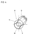
- FIG. 4 A simple and inexpensive embodiment of a snap-in sliding connection (G) is shown in FIG. 4.
- the shaft (W) or the shaft (X) can each have two locking recesses (V) which have predetermined positions, a predetermined depth and a position in relation to the position of the throttle valve (D) have a predetermined width.
- a two-armed, omega-shaped spring (O) is provided, which is connected to the other shaft (X, W) and whose free, inwardly bent arms can engage in the snap-in connections or on the outer surface the respective shaft (X, Y) can slide.
- the design of the locking recesses (V) and the omega-shaped spring (O) can vary depending on the required locking forces, the sliding forces and the frictional forces of the shafts (W, X, Y).
- the snap-slide connection assigned to the second stop (A2) can have the same or a similar structure.
- the possible embodiments and combinations of the coupling devices (K1, K2, K3) in the throttle valve (D) according to the invention are not limited to the exemplary embodiments shown in FIGS. 1 to 3.
- the type of coupling of the coupling devices (K1, K2, K3) can vary, so that different combinations of the coupling devices and the type of coupling devices (K1, K2, K3) can also result.
- the servomotor (M) can be designed as an electric motor.
- the servomotor (M) can also be designed as a pneumatically operated motor.
- the servomotor (M) and the cable (S) can be located on opposite sides of the throttle valve (D). In another embodiment, there may also be an arrangement in which which the cable (S) and the servomotor (M) are arranged on one side of the throttle valve (D).
- servomotors are used in order to regulate the motor torque of a motor vehicle via the throttle valve (D) as a function of predetermined or calculated control variables.
- the intervention in the engine torque of a motor vehicle requires a high level of security when the throttle valve (D) is actuated by the servomotor (M).
- the throttle valve (D) is adjusted via a cable pull (S) which is actuated via an accelerator pedal.
- the cable (S) is connected to at least one return spring (R) which, when the accelerator pedal is released, puts the throttle valve (D) in the closed position.
- a first coupling device (K1) is provided, which generates a fixed coupling of the shaft (W) with the shaft (Y) in a predetermined position of the first stop (A1) and releases this coupling when the servomotor (M) engages .
- a second coupling device (K2) is provided which, apart from the case that a malfunction of the Actuator (M) occurs or an emergency function of the throttle valve (D) is switched, couples the actuator (M) to the shaft (W).
- the servomotor (M) can be adjusted without any delay and very precisely the throttle valve (D) when the throttle valve (D) is required to be actuated by the servomotor (M).
- the servomotor (M) adjusts the throttle valve (D) between the closed position and the maximum open position.
- the servomotor can only adjust the throttle valve between the closed position and the instantaneous maximum position of the throttle valve (D) specified by the cable (S).
- the cable pull (S) is assigned a setpoint potentiometer (SP), from which a voltage can be tapped that can Specifies the setpoint for the position of the throttle valve (D) and the actuator (M) is assigned an actual value potentiometer (IP), from which a voltage can be tapped that corresponds to the actual position of the throttle valve (D).
- SP setpoint potentiometer
- IP actual value potentiometer
- B. can put the servomotor (M) out of operation and or can open and / or close the first and / or second coupling device (K1, K2), can output error signals and can activate an emergency operation circuit.
- a speed controller actuation device can be connected to the rope pulley (SB) in a simple and inexpensive manner, so that the throttle valve (D) can be actuated by a speed controller without that z. B. needs to be dispensed with a traction control and a corresponding control by the servomotor (M).
Landscapes
- Engineering & Computer Science (AREA)
- Chemical & Material Sciences (AREA)
- Combustion & Propulsion (AREA)
- Mechanical Engineering (AREA)
- General Engineering & Computer Science (AREA)
- Control Of Throttle Valves Provided In The Intake System Or In The Exhaust System (AREA)
Abstract
Description
- Die Erfindung betrifft eine Drosselklappe für eine Brennkraftmaschine, die auf einer Welle gelagert ist, mit einem Seilzug, durch den die Welle verdrehbar ist, mindestens einer Rückholfeder an dem Seilzug, einem ersten Anschlag zwischen dem Seilzug und der Welle, einer ersten Kopplungseinrichtung zwischen dem Seilzug und der Welle und einem Stellmotor.
- Aus der deutschen Offenlegungsschrift DE-OS 37 11 779 ist eine Drosselklappe dieser Art bekannt. Die Drosselklappe ist dabei auf einer Welle gelagert, die durch einen Seilzug verdrehbar ist. Der Seilzug wird dabei durch eine Rückholfeder mit Kraft in Schließrichtung der Drosselklappe beaufschlagt. Die Drosselklappe weist zudem einen ersten Anschlag zwischen dem Seilzug und der Welle auf, dessen Anschlagpunkt mit Hilfe des Seilzugs verlegt wird, wobei die Drosselklappe zwischen ihrer Schließstellung und der Anschlagstellung bewegbar ist. Zwischen dem Seilzug und der Welle ist dabei eine Kopplungseinrichtung angeordnet, die hier als eine Feder ausgebildet ist. Für den regelnden Eingriff auf das Motordrehmoment z. B. bei dem Auftreten von Schlupf an einem der angetriebenen Räder des Kraftfahrzeugs weist die Drosselklappe einen Stellmotor auf, der die Drosselklappe betätigen kann. Der Stellmotor ist dabei über einen zweiten Anschlag mit der Welle verbunden, dessen Anschlagpunkt mit Hilfe des Stellmotors vorverlegbar ist, so daß die Drosselklappe in Schließrichtung betätigbar ist.
- Als besonders nachteilig erweist sich hierbei, daß bei dem Betrieb der Drosselklappe durch den Stellmotor der Stellmotor immer gegen die Federkraft der Feder anarbeiten muß, die den Seilzug mit der Welle verbindet. Da die Federkraft mit zunehmender Auslenkung größer wird, ist somit ein Stellmotor erforderlich, der eine hohe Leistung aufweist, wodurch sich eine teuere Ausführung ergibt. In diesem Zusammenhang erweist sich zudem als nachteilig, daß aufgrund der von dem Stellmotor aufzubringenden Kraft die Lebensdauer des Stellmotors herabgesetzt wird, so daß die Sicherheit und Zuverlässigkeit bei dem Betrieb des Kraftfahrzeugs, insbesondere bei einer sicherheitsrelevanten Einrichtung, wie einer Drosselklappe, herabgesetzt wird.
- Weiterhin erweist sich als nachteilig, daß der Stellmotor bei einer Betätigung der Drosselklappe durch den Seilzug nicht automatisch nachgeführt wird, so daß bei einem erforderlichen Eingriff des Stellmotors auf die Drosselklappenstellung sich eine unerwünschte Verzögerung ergibt, die sich nachteilig auf das Regelverhalten, z. B. einer Antriebschlupfregelung für ein Kraftfahrzeug, auswirken kann.
- Der Erfindung liegt die Aufgabe zugrunde, eine Drosselklappe zu schaffen, die bei einer möglichst einfachen und kostengünstigen Ausführung die Sicherheit und Zuverlässigkeit bei dem Betrieb des Kraftfahrzeugs erhöht und den Stellmotor bei dessen Betrieb von einer großen, die Drosselklappe rückstellenden Kraft entlastet.
- Die Aufgabe wird erfindungsgemäß dadurch gelöst, daß die erste Kopplungseinrichtung eine erste Kupplung ist, die einen sich verändernden oder aufhebbaren Kraftschluß aufweist, wobei der Kraftschluß in dem unmittelbaren Bereich des veränderlichen Anschlagpunktes am größten ist.
- Es ist von Vorteil, daß die erste Kopplungseinrichtung eine erste Kupplung ist, die einen sich verändernden oder aufhebbaren Kraftschluß aufweist, wobei der Kraftschluß in dem unmittelbaren Bereich des veränderlichen Anschlagpunktes am größten ist, weil somit bei einem Betrieb der Drosselklappe durch den Stellmotor der Stellmotor nur geringe Kräfte zum Verstellen der Drosselklappe aufbringen muß, wodurch der Stellmotor in besonders einfacher und kostengünstiger Weise als ein Stellmotor mit einer geringen Leistung ausgelegt werden kann und zusätzlich aufgrund der Entlastung des Stellmotors von einer großen, die Drosselklappe rückstellenden Kraft die Zuverlässigkeit und Sicherheit bei dem Betrieb des Kraftfahrzeugs erhöht wird, da die Lebensdauer des Stellmotors erhöht wird.
- Dadurch, daß eine zweite Kopplungseinrichtung zwischen der Welle und dem Stellmotor angeordnet ist, die den Stellmotor mit der Welle kraftschlüssig verbindet oder verbinden kann, ergibt sich der Vorteil, daß der Stellmotor auf besonders einfache und kostengünstige Weise zum einen die Drosselklappe betätigen kann und zum anderen bei einer Betätigung der Drosselklappe durch den Seilzug immer zwangsläufig der Stellung der Drosselklappe nachgeführt wird, so daß bei jedem erforderlichen Betreiben der Drosselklappe durch den Stellmotor ein sofortiger Eingriff durch den Stellmotor ermöglicht wird, wodurch das Regelverhalten z. B. einer Antriebsschlupfregelung erheblich verbessert wird.
- In diesem Zusammenhang ist es vorteilhaft, daß die zweite Kopplungseinrichtung aus einer Feder besteht, die zwischen dem Stellmotor und der Welle angeordnet ist, da sich somit eine besonders einfache und kostengünstige Ausführungsform ergibt, die eine besonders hohe Zuverlässigkeit aufweist.
- Es ist vorteilhaft, daß die zweite Kopplungseinrichtung eine zweite Kupplung ist, die einen sich verändernden oder aufhebbaren Kraftschluß aufweist, weil somit zum einen ein besonders zuverlässiges Nachführen des Stellmotors bei einer Betätigung der Drosselklappe durch den Seilzug gewährleistet wird und zum anderen sichergestellt wird, daß z. B. bei einem Blockieren des Stellmotors eine Bewegung der Drosselklappe durch den Seilzug sichergestellt wird.
- Dadurch, daß die erste und/oder zweite Kupplung jeweils als eine Rast-Gleitverbindung ausgebildet ist, ergibt sich der Vorteil, daß für eine vorgegebene Stellung der Welle zu dem Seilzug oder dem Stellmotor eine feste Kopplung zwischen der Welle und dem Seilzug oder der Welle und dem Stellmotor sichergestellt ist und daß für die weiteren Stellungen der Welle zu dem Seilzug und der Welle zu dem Stellmotor nur eine geringe Kraft erforderlich ist, um die Welle durch den Seilzug oder den Stellmotor zu verdrehen.
- Dadurch, daß die Rast-Gleitverbindung aus einer zweiarmigen omegaförmigen Feder und mindestens zwei Rastvertiefungen auf einer der Wellen besteht, ergibt sich der Vorteil einer besonders einfachen und kostengünstigen Ausführung der Rast-Gleitverbindungen, die eine hohe Zuverlässigkeit aufweisen.
- Es ist besonders vorteilhaft, wenn die erste und/oder zweite Kupplung eine pneumatisch oder elektrisch oder hydraulisch betätigbare Kupplung ist, weil somit ein besonders zuverlässiges Ankoppeln und Lösen des Seilzugs an die Drosselklappe und/oder des Stellmotors an die Drosselklappe gewährleistet wird, wodurch die Sicherheit und die Zuverlässigkeit bei dem Betrieb des Kraftfahrzeugs erheblich erhöht wird, ohne daß die Kosten für die Drosselklappe zu hoch werden.
- Dadurch, daß dem Stellmotor ein Istwertpotentiometer zugeordnet ist, ergibt sich der Vorteil, daß bei einer zuverlässigen Nachführung des Stellmotors bei der Betätigung der Drosselklappe die Iststellung der Drosselklappe und des Stellmotors jederzeit zuverlässig festgestellt werden kann und einer Regeleinrichtung zugeführt werden kann.
- In diesem Zusammenhang ist es vorteilhaft, daß dem Seilzug ein Sollwertpotentiometer zugeordnet ist, wodurch auf einfache und kostengünstige Weise die Sollstellung der Drosselklappe bestimmt werden kann.
- Als besonders vorteilhaft erweist sich dabei, daß eine Diagnoseeinrichtung mit dem Istwertpotentiometer und dem Sollwertpotentiometer verbunden ist, wodurch Fehleinstellungen der Drosselklappe und/oder des Stellmotors und/oder der ersten oder zweiten Kopplungseinrichtung einfach und zuverlässig erkannt werden können, Fehlermeldungen ausgegeben werden können und eine Notlaufschaltung aktiviert werden kann, wodurch die Zuverlässigkeit und Sicherheit bei dem Betrieb des Kraftfahrzeugs erhöht wird.
- Es ist vorteilhaft, daß eine Geschwindigkeitsreglerbetätigungseinrichtung mit dem Seilzug verbunden ist, weil somit auf einfache und kostengünstige Weise ein Geschwindigkeitsregler mit der Drosselklappe verbindbar ist und somit das Kraftfahrzeug neben der Betätigung der Drosselklappe durch einen Seilzug, der mit einem Gaspedal gekoppelt ist, auch eine Betätigung durch einen Geschwindigkeitsregler ermöglicht wird, wobei auch bei dem Betrieb der Drosselklappe durch den Geschwindigkeitsregler der Stellmotor z. B. für eine Antriebsschlupfregelfunktion uneingeschränkt zur Verfügung steht.
- Dadurch, daß die Betätigungseinrichtung über eine dritte Kopplungseinrichtung, die eine Feder oder eine Kupplung mit veränderlichem oder aufhebbaren Kraftschluß ist, mit der Seilscheibe verbunden ist, ergibt sich der Vorteil, daß der Geschwindigkeitsregler auf besonders einfache und zuverlässige Weise an die Drosselklappe ankoppelbar ist, wodurch sich eine hohe Sicherheit bei dem Betrieb des Kraftfahrzeugs ergibt. Die Geschwindigkeitsreglerbetätigungseinrichtung kann somit bei einem Betrieb der Drosselklappe durch den Seilzug jederzeit der Bewegung des Seilzugs nachgeführt werden, wodurch sich bei einem erforderlichen Eingriff des Geschwindigkeitsreglers der Vorteil ergibt, daß dieser ohne Verzögerung die Drosselklappe verstellen kann. In diesem Zusammenhang ist es von Vorteil, daß zwischen der Betätigungseinrichtung und dem Seilzug ein dritter Anschlag angeordnet ist, weil somit sichergestellt wird, daß bei einem Betreiben der Drosselklappe durch den Geschwindigkeitsregler eine sichere Verbindung zwischen dem Geschwindigkeitsregler und der Welle für eine Verstellung der Drosselklappe in Richtung offen hergestellt wird, wobei gleichzeitig ein Rückstellen der Geschwindigkeitsreglerbetätigungseinrichtung durch die Rückstellfeder sichergestellt ist, wodurch sich eine besonders hohe Sicherheit bei dem Betreiben des Kraftfahrzeugs ergibt.
- Es ist vorteilhaft, daß der Seilzug an eine Seilscheibe ankoppelt, wodurch sich eine besonders einfache und kostengünstige Anlenkung des Seilzugs ergibt.
- Es ist besonders vorteilhaft, daß zwischen der Welle und dem Stellmotor ein zweiter Anschlag angeordnet ist, wodurch sichergestellt wird, daß bei einem Betrieb der Drosselklappe durch den Stellmotor der Stellmotor ohne Verzögerung und mit hoher Sicherheit in Richtung Schließen betätigt werden kann.
- Ausführungsbeispiele der Erfindung sind in den Zeichnungen dargestellt und werden im folgenden anhand der Zeichnungen näher beschrieben.
- Es zeigen
- Figur 1 ein erstes Ausführungsbeispiel anhand einer Systemdarstellung der erfindungsgemäßen Drosselklappe,
- Figur 2 ein zweites Ausführungsbeispiel der erfindungsgemäßen Drosselklappe,
- Figur 3 ein drittes Ausführungsbeispiel der erfindungsgemäßen Drosselklappe,
- Figur 4 ein Ausführungsbeispiel einer Rast-Gleitverbindung, entsprechend Figur 3.
- Gleiche oder gleichwirkende Bauteile sind in allen Figuren mit gleichen Bezugszeichen versehen.
- Figur 1 zeigt ein erstes Ausführungsbeispiel der erfindungsgemäßen Drosselklappe anhand einer Systemzeichnung.
- Die Drosselklappe (D) ist auf einer Welle (W) gelagert, die durch den Seilzug (S) verdrehbar ist. Der Seilzug (S) ist hier beispielhaft für eine besonders einfache Anlenkung mit einer Seilscheibe (SB) verbunden. Die Seilscheibe (SB) wird dabei durch mindestens eine Rückstellfeder (R) mit Kraft in Schließrichtung der Drosselklappe (D) beaufschlagt. Die Seilscheibe (SB) ist dabei auf einer Welle (X) gelagert, die auch in Verbindung mit einem Sollwertpotentiometer (SP) steht und dieses bei einer Betätigung der Seilscheibe (SB) und des Seilzugs (S) verstellt, so daß einer Regeleinrichtung oder einer Diagnoseeinrichtung, die hier nicht gezeigt werden, ein Sollwertsignal für die Stellung der Drosselklappe (D) zugeführt werden kann. Auf der Welle (X) ist zudem ein erstes Teil eines ersten Anschlags (A1) gelagert, dessen Anschlagpunkt durch den Seilzug (S) verlegt werden kann, wobei die Drosselklappe (D) zwischen ihrer Schließstellung und der Anschlagstellung bewegbar ist.
- Zwischen dem ersten Teil und dem zweiten Teil des Anschlags (A1) ist eine erste Kopplungseinrichtung (K1) angeordnet, die eine erste Kupplung (K1) ist und einen sich verändernden oder aufhebbaren Kraftschluß aufweist, wobei der Kraftschluß in dem unmittelbaren Bereich des veränderlichen Anschlagpunktes am größten ist. Der zweite Teil des Anschlags (A1) ist fest mit der Welle (W) verbunden.
- Die Drosselklappe (D) weist zudem einen Stellmotor (M) auf, der auf einer Welle (Y) gelagert ist und der in Abhängigkeit von vorgegebenen oder errechneten Regelgrößen die Drosselklappe (D) über die Welle (W) verstellt.
- Zur Ermittlung der Istposition der Stellung des Stellmotors (M) und der Stellung der Drosselklappe (D) ist dem Stellmotor (M) ein Istwertpotentiometer (IP) zugeordnet. Eine zweite Kopplungseinrichtung (K2) ist zwischen der Welle (W) und der Welle (Y) und somit dem Stellmotor (M) angeordnet, die den Stellmotor (M) mit der Welle (W) kraftschlüssig verbindet oder verbinden kann.
- Zur Betätigung der Drosselklappe (D) mittels einer Geschwindigkeitsreglerbetätigungseinrichtung (GR), die mit einem Geschwindigkeitsregler verbunden ist, ist die Seilscheibe (SB) über eine dritte Kopplungseinrichtung (K3), die als eine Feder oder eine Kupplung mit veränderlichem oder aufhebbarem Kraftschluß ausgebildet sein kann, mit der Geschwindigkeitsreglerbetätigungseinrichtung (GR) verbunden oder verbindbar. Zudem ist die Geschwindigkeitsreglerbetätigungseinrichtung (GR) über einen dritten Anschlag (A3) mit der Seilscheibe (SB) verbunden, wodurch zum einen sichergestellt wird, daß bei einer Betätigung der Drosselklappe (D) durch den Geschwindigkeitsregler aufgrund der Kopplung durch die dritte Kopplungseinrichtung (K3) ein unverzögerter Eingriff des Geschwindigkeitsreglers erfolgen kann und zudem die Geschwindigkeitsreglerbetätigungseinrichtung (GR) durch die Rückstellfeder (R) mit Kraft in Schließrichtung der Drosselklappe (D) beaufschlagt wird.
- Für die Ausbildung der ersten und zweiten Kopplungseinrichtungen (K1, K2) ergeben sich beispielhaft die im folgenden beschriebenen Ausführungsformen.
- Die in Figur 1 gezeigte erste Kopplungseinrichtung (K1) kann z. B. als eine elektrische oder pneumatische oder hydraulische Kupplung (K1) ausgebildet sein, die in Abhängigkeit von den Signalen von dem Istwertpotentiometer (IP) und dem Sollwertpotentiometer (SP) durch eine nicht gezeigte Regeleinrichtung oder Diagnoseeinrichtung angesteuert wird. Befinden sich das erste und das zweite Teil des ersten Anschlags am Anschlagspunkt, so wird die erste Kupplung (K1) geschlossen. Sobald eine Ansteuerung der Drosselklappe durch den Stellmotor (M) erforderlich ist, wird die erste Kupplung (K1) geöffnet, um den Stellmotor (M) zu entlasten, so daß dieser als ein einfacher Stellmotor mit geringer Leistung ausgebildet sein kann, so daß sich insgesamt eine kostengünstige Ausführung ergibt.
- Damit der Stellmotor (M) an die Welle (W) ankoppelbar und auch von dieser entkoppelbar ist, ist zwischen der Welle (Y) und der Welle (W) eine zweite Kopplungseinrichtung (K2) angeordnet, die als eine zweite Kupplung (K2) ausgebildet sein kann, die einen sich verändernden oder aufhebbaren Kraftschluß aufweisen kann.
- Die zweite Kupplung (K2) kann dabei auch als eine elektrische oder pneumatische oder hydraulisch betätigbare Kupplung (K2) ausgebildet sein, die von einer nicht gezeigten Regeleinrichtung oder Diagnoseeinrichtung angesteuert wird. Es ist dabei vorteilhaft, daß die zweite Kupplung (K2) außer bei einer vorliegenden Fehlfunktion des Stellmotors (M) geschlossen ist, so daß der Stellmotor (M) jederzeit der Drehbewegung der Welle (W) folgt und bei einem erforderlichen Eingriff des Stellmotors (M) somit gewährleistet ist, daß der Stellmotor (M) ohne Verzögerung die Welle (W) verstellen kann. Für den Fall, daß eine Fehlfunktion des Stellmotors (M) vorliegt oder eine Notlauffunktion geschaltet werden muß, kann die zweite Kupplung (K2) geöffnet werden, so daß die Drosselklappe (D) frei durch den Seilzug (S) verstellbar ist.
- Bei der Ausführung der ersten und/oder zweiten Kupplung (K1, K2) als eine elektrisch oder pneumatisch oder hydraulisch betätigbare Kupplung (K1, K2) ergibt sich der besondere Vorteil einer sehr hohen Zuverlässigkeit bei der Betätigung und einer sehr hohen Anpaßfähigkeit an die erforderlichen Regelvorgänge, die durch die nicht gezeigte Regeleinrichtung gesteuert werden, wobei sich trotzdem eine kostengünstige Ausführung ergibt.
- Das in Figur 2 gezeigte Ausführungsbeispiel unterscheidet sich von dem in Figur 1 gezeigten Ausführungsbeispiel lediglich durch eine andere Ausführung der zweiten Kopplungseinrichtung (K2). Die zweite Kopplungseinrichtung (K2) ist hier für eine besonders einfache und kostengünstige Ausführung als eine Feder (F) ausgebildet, durch die die Welle (W) an die Welle (Y) und damit den Stellmotor (M) ankoppelt. Bei jeder Verstellung der Welle (W) durch den Seilzug (S) folgt somit der Stellmotor (M) der Bewegung der Drosselklappe (D), so daß der Stellmotor jederzeit ohne Verzögerung bei einer Ansteuerung durch eine nicht gezeigte Regeleinrichtung die Drosselklappe verstellen kann, was insbesondere bei einer sicherheitsrelevanten Regeleinrichtung, wie einer Antriebsschlupfregeleinrichtung, für eine hohe Sicherheit von Vorteil ist. Zur Erhöhung der Sicherheit bei einem erforderlichen Betrieb der Drosselklappe (D) durch den Stellmotor (M) kann die Welle (Y) mit der Welle (W) über einen zweiten Anschlag (A2) verbunden sein, dessen Anschlagpunkt mit Hilfe des Stellmotors vorverlegbar ist, so daß die Drosselklappe in Schließrichtung betätigbar ist.
- In Figur 3 ist ein weiteres Ausführungsbeispiel der erfindungsgemäßen Drosselklappe dargestellt. Die in Figur 3 dargestellte Ausführungsform unterscheidet sich von den in Figur 1 und Figur 2 dargestellten Ausführungsformen einzig durch die andere Ausgestaltung der ersten und zweiten Kopplungseinrichtungen (K1, K2). Die Kopplungseinrichtungen (K1, K2) sind hier beispielhaft als Rast-Gleitverbindungen (G) ausgeführt, die in Figur 3 nur grob skizziert sind. Die Rast-Gleitverbindungen (G) sind dabei derart ausgestaltet und angeordnet, daß in dem unmittelbaren Bereich des Anschlagpunktes der Anschläge (A1, A2) die ersten und zweiten Teile der Anschläge (A1, A2) miteinander verrasten, so daß in dieser Position bei einer Betätigung der Drosselklappe durch den Seilzug (S) sich zwischen der Welle (Y) und der Welle (W) eine feste Verbindung ergibt, die auch zwischen der Welle (W) und der Welle (X) hergestellt wird. Bei einem erforderlichen Eingriff des Stellmotors (M) zur Verstellung der Drosselklappe (D) wird die Welle (W) durch den Stellmotor (M) mit einer Kraft bewegt, die groß genug ist, um die Rastkraft der Rast-Gleitverbindung (G) in Bezug auf den ersten Anschlag (A1) zu überwinden, so daß nach Überwindung der vorliegenden Rastkraft durch den Stellmotor (M) lediglich eine Kraft zur Verstellung der Drosselklappe (D) und zur Überwindung der bei der Rast-Gleitverbindung (G) auftretenden Gleitkraft aufzubringen ist. Dadurch kann der Motor eine kleinere Leistung aufweisen, wodurch sich insgesamt eine einfachere und kostengünstigere Ausführung ergibt.
- Auch die zweite Kopplungseinrichtung (K2) kann als eine Rast-Gleitverbindung (G) ausgebildet sein, die auch in dem unmittelbaren Bereich des Anschlagpunktes des zweiten Anschlags (A2) verrastet und somit sicherstellt, daß der Stellmotor (M) der Bewegung der Drosselklappe (D) folgt. Für den Fall einer Fehlfunktion des Stellmotors (M) oder bei der Einschaltung einer Notlauffunktion für die Drosselklappe (D) ist bei Überwindung der Rastkraft sichergestellt, daß die Drosselklappe (D) durch den Seilzug (S) uneingeschränkt bewegbar ist, wodurch sich eine hohe Sicherheit bei dem Betrieb des Kraftfahrzeugs ergibt.
- Ein einfaches und kostengünstiges Ausführungsbeispiel einer Rast-Gleitverbindung (G) ist in der Figur 4 dargestellt. Je nach der Anordnung der Rast-Gleitverbindung (G) kann die Welle (W) oder die Welle (X) je zwei Rastvertiefungen (V) aufweisen, die in Bezug auf die Stellung der Drosselklappe (D) vorgegebene Positionen, eine vorgegebene Tiefe und eine vorgegebene Breite aufweisen. Zur Bildung einer Rast-Gleitverbindung (G) ist eine zweiarmige, omegaförmige Feder (O) vorgesehen, die mit der jeweils anderen Welle (X, W) verbunden ist und deren freie, nach innen gebogenen Arme in die Rastverbindungen eingreifen können oder auf der Mantelfläche der jeweiligen Welle (X, Y) gleiten können. Die Ausführung der Rastvertiefungen (V) und der omegaförmigen Feder (O) kann dabei in Abhängigkeit von den erforderlichen Rastkräften, den Gleitkräften und den Reibkräften der Wellen (W, X, Y) variieren. Die dem zweiten Anschlag (A2) zugeordnete Rast-Gleitverbindung kann dabei einen gleichen oder ähnlichen Aufbau aufweisen.
- Die möglichen Ausführungsformen und Kombinationen der Kopplungseinrichtungen (K1, K2, K3) beschränken sich bei der erfindungsgemäßen Drosselklappe (D) nicht auf die in den Figuren 1 bis 3 gezeigten Ausführungsbeispiele. Je nach der erforderlichen Ausführungsform kann die Art der Kopplung der Kopplungseinrichtungen (K1, K2, K3) variieren, so daß sich auch jeweils andere Kombinationen der Kopplungseinrichtungen und der Art der Kopplungseinrichtungen (K1, K2, K3) ergeben können.
- Der Stellmotor (M) kann bei einer besonders kostengünstigen Ausführungsform als ein Elektromotor ausgebildet sein. Der Stellmotor (M) kann jedoch auch als ein pneumatisch betätigter Motor ausgebildet sein.
- Wie in den Figuren 1 bis 3 gezeigt, können sich der Stellmotor (M) und der Seilzug (S) auf gegenüberliegenden Seiten der Drosselklappe (D) befinden. Bei einem anderen Ausführungsbeispiel kann auch eine Anordnung vorliegen, bei der der Seilzug (S) und der Stellmotor (M) auf einer Seite der Drosselklappe (D) angeordnet sind.
- Im folgenden wird kurz die Wirkungsweise der Drosselklappe für eine Brennkraftmaschine beschrieben.
- Beispielsweise bei einem E-Gas oder einer Antriebsschlupfregelung für Kraftfahrzeuge werden Stellmotoren (M) verwendet, um in Abhängigkeit von vorgegebenen oder errechneten Regelgrößen über die Drosselklappe (D) das Motordrehmoment eines Kraftfahrzeugs zu regeln. Der Eingriff auf das Motordrehmoment eines Kraftfahrzeugs erfordert eine hohe Sicherheit bei der Ansteuerung der Drosselklappe (D) durch den Stellmotor (M). Bei einem normalen Betrieb der Kraftfahrzeugs wird die Drosselklappe (D) über einen Seilzug (S) verstellt, der über ein Gaspedal betätigt wird. Der Seilzug (S) ist mit mindestens einer Rückstellfeder (R) verbunden, die bei einer Entlastung das Gaspedals die Drosselklappe (D) in die Schließstellung versetzt. Bei der Verstellung der Drosselklappe (D) durch den Seilzug (S) ist es dabei erforderlich, daß die Welle (W), auf der die Drosselklappe (D) gelagert ist, fest mit der Welle (Y) verbunden ist, auf der z. B. eine Seilscheibe (SB) gelagert ist, an die der Seilzug (S) ankoppelt.
- Bei dem Betriebszustand, bei dem die Drosselklappe (D) durch den Stellmotor (M) verstellt wird, ist es es jedoch von Vorteil, daß die feste Verbindung zwischen der Welle (W) und der Welle (X) gelöst wird, damit der Stellmotor keine hohe Rückstellkraft überwinden muß, um die Drosselklappe (D) verstellen zu können. Aus diesem Grund ist eine erste Kopplungseinrichtung (K1) vorgesehen, die in einer vorgegebenen Position des ersten Anschlags (A1) eine feste Kopplung der Welle (W) mit der Welle (Y) erzeugt und bei einem Eingriff des Stellmotors (M) diese Kopplung löst.
- Damit der Stellmotor (M) jederzeit bei dem Betrieb der Drosselklappe (D) durch den Seilzug (S) der Bewegung der Drosselklappe (D) nachgeführt wird, ist eine zweite Kopplungseinrichtung (K2) vorgesehen, die bis auf den Fall, daß eine Fehlfunktion des Stellmotors (M) auftritt oder eine Notlauffunktion der Drosselklappe (D) geschaltet wird, den Stellmotor (M) an die Welle (W) ankoppelt. Damit ergibt sich der Vorteil, daß der Stellmotor (M) bei einer erforderlichen Ansteuerung der Drosselklappe (D) durch den Stellmotor (M) ohne Verzögerung und sehr exakt die Drosselklappe (D) verstellen kann. Bei einem E-Gas für ein Kraftfahrzeug verstellt der Stellmotor (M) dabei die Drosselklappe (D) zwischen der Schließstellung und der maximal geöffneten Stellung. Bei einer Einrichtung zur Antriebsschlupfregelung ist es jedoch vorteilhaft, wenn der Stellmotor die Drosselklappe lediglich zwischen der Schließstellung und der durch den Seilzug (S) vorgegebenen momentanen Maximalstellung der Drosselklappe (D) verstellen kann.
- Zur Überwachung der einwandfreien Funktion des Stellmotors (M) der ersten und zweiten Kopplungseinrichtungen (K1, K2) und der Stellung der Drosselklappe (D) ist dem Seilzug (S) ein Sollwertpotentiometer (SP) zugeordnet, an dem eine Spannung abgreifbar ist, die einen Sollwert für die Stellung der Drosselklappe (D) vorgibt und ist dem Stellmotor (M) ein Istwertpotentiometer (IP) zugeordnet, an dem eine Spannung abgreifbar ist, die der Iststellung der Drosselklappe (D) entspricht. Diese Spannungen können einer Diagnoseeinrichtung zugeführt werden, die Teil einer Regeleinrichtung sein kann und die bei vorliegenden Abweichungen z. B. den Stellmotor (M) außer Betrieb setzen kann und oder die erste und/oder zweite Kopplungseinrichtung (K1, K2) öffnen und/oder schließen kann, Fehlersignale ausgeben kann und eine Notlaufschaltung aktivieren kann.
- Über eine dritte Kopplungseinrichtung (K3) und einen dritten Anschlag (K3) kann auf einfache und kostengünstige Art und Weise eine Geschwindigkeitsreglerbetätigungseinrichtung (GR) mit der Seilscheibe (SB) verbunden werden, so daß die Drosselklappe (D) durch einen Geschwindigkeitsregler betätigbar ist, ohne daß z. B. auf eine Antriebsschlupfregelung und eine entsprechende Ansteuerung durch den Stellmotor (M) verzichtet werden braucht.
Claims (15)
Applications Claiming Priority (2)
| Application Number | Priority Date | Filing Date | Title |
|---|---|---|---|
| DE3936875 | 1989-11-06 | ||
| DE3936875A DE3936875A1 (de) | 1989-11-06 | 1989-11-06 | Drosselklappe fuer eine brennkraftmaschine |
Publications (2)
| Publication Number | Publication Date |
|---|---|
| EP0427097A1 true EP0427097A1 (de) | 1991-05-15 |
| EP0427097B1 EP0427097B1 (de) | 1994-12-14 |
Family
ID=6392947
Family Applications (1)
| Application Number | Title | Priority Date | Filing Date |
|---|---|---|---|
| EP90120854A Expired - Lifetime EP0427097B1 (de) | 1989-11-06 | 1990-10-31 | Drosselklappe für eine Brennkraftmaschine |
Country Status (3)
| Country | Link |
|---|---|
| US (1) | US5074266A (de) |
| EP (1) | EP0427097B1 (de) |
| DE (2) | DE3936875A1 (de) |
Cited By (2)
| Publication number | Priority date | Publication date | Assignee | Title |
|---|---|---|---|---|
| GB2259550A (en) * | 1991-09-10 | 1993-03-17 | Hella Kg Hueck & Co | Motor vehicle engine throttle valve actuation |
| US7044019B2 (en) | 2002-05-24 | 2006-05-16 | Ab Elektronik Gmbh | Accelerator pedal |
Families Citing this family (13)
| Publication number | Priority date | Publication date | Assignee | Title |
|---|---|---|---|---|
| DE4027269A1 (de) * | 1990-08-29 | 1992-03-05 | Vdo Schindling | Drosselklappenstutzen |
| DE4028702A1 (de) * | 1990-09-10 | 1992-03-12 | Bosch Gmbh Robert | Stelleinrichtung |
| DE4034575A1 (de) * | 1990-10-31 | 1992-05-07 | Vdo Schindling | Lastverstelleinrichtung |
| JP3205002B2 (ja) * | 1991-05-20 | 2001-09-04 | 株式会社日立製作所 | スロットルアクチュエータ |
| JPH0650201A (ja) * | 1992-04-30 | 1994-02-22 | Nippondenso Co Ltd | スロットル弁の駆動装置 |
| US5479908A (en) * | 1994-05-26 | 1996-01-02 | Ingersoll-Rand Company | Engine speed control device |
| DE69627506T3 (de) * | 1995-01-17 | 2014-03-06 | Hitachi, Ltd. | Luftströmungssteuervorrichtung |
| JPH10121992A (ja) * | 1996-10-18 | 1998-05-12 | Mitsubishi Electric Corp | 機関のスロットル弁制御装置 |
| US6895983B2 (en) * | 2002-09-26 | 2005-05-24 | The Chemithon Corporation | Method and apparatus for dividing the flow of a gas stream |
| DE102006036429A1 (de) * | 2006-08-04 | 2008-02-07 | Bayerische Motoren Werke Ag | Einrichtung und Verfahren zur Betätigung einer Leistungssteuerungseinrichtung einer Brennkraftmaschine |
| DE102006036426A1 (de) * | 2006-08-04 | 2008-02-07 | Bayerische Motoren Werke Ag | Einrichtung und Verfahren zur Betätigung einer Leistungssteuerungseinrichtung einer Brennkraftmaschine |
| DE102006036428B4 (de) * | 2006-08-04 | 2020-11-19 | Bayerische Motoren Werke Aktiengesellschaft | Einrichtung und Verfahren zur Betätigung einer Leistungssteuerungseinrichtung einer Brennkraftmaschine |
| DE102006036427B4 (de) * | 2006-08-04 | 2020-09-24 | Bayerische Motoren Werke Aktiengesellschaft | Einrichtung und Verfahren zur Betätigung einer Leistungssteuerungseinrichtung einer Brennkraftmaschine |
Citations (5)
| Publication number | Priority date | Publication date | Assignee | Title |
|---|---|---|---|---|
| US4523565A (en) * | 1984-03-30 | 1985-06-18 | Aisin Seiki Kabushiki Kaisha | Control system and method for a fuel delivery system |
| DE3711779A1 (de) * | 1987-04-08 | 1988-10-20 | Audi Ag | Drosselklappe |
| US4860708A (en) * | 1987-06-03 | 1989-08-29 | Honda Giken Kogyo Kabushiki Kaisha | Throttle control system for automotive internal combustion engine |
| DE3809910A1 (de) * | 1988-03-24 | 1989-10-05 | Vdo Schindling | Vorrichtung zur leistungsbeeinflussung von brennkraftmaschinen |
| EP0389649A1 (de) * | 1989-03-25 | 1990-10-03 | Audi Ag | Drosselklappe |
Family Cites Families (8)
| Publication number | Priority date | Publication date | Assignee | Title |
|---|---|---|---|---|
| DE3719323A1 (de) * | 1987-06-10 | 1988-12-29 | Bosch Gmbh Robert | Vorrichtung zur betaetigung der drosselklappe einer brennkraftmaschine |
| DE3730239A1 (de) * | 1987-09-09 | 1989-03-30 | Pierburg Gmbh | Elektrisch ansteuerbare stellvorrichtung zum verstellen der drosselklappe einer brenngemischdrosseleinrichtung von brennkraftmaschinen |
| JPS6473134A (en) * | 1987-09-14 | 1989-03-17 | Mazda Motor | Throttle valve opening control device for vehicle |
| DE3814702A1 (de) * | 1987-11-12 | 1989-05-24 | Bosch Gmbh Robert | Vorrichtung zum betaetigen der drosselklappe einer brennkraftmaschine insbesondere eines kraftfahrzeuges |
| DE3811892A1 (de) * | 1988-04-09 | 1989-10-19 | Bosch Gmbh Robert | Vorrichtung zur regelung einer brennkraftmaschine in fahrzeugen |
| DE3813047A1 (de) * | 1988-04-19 | 1989-11-02 | Pierburg Gmbh | Verstelleinrichtung fuer die drosselklappe einer gemischbildungseinrichtung fuer brennkraftmaschinen |
| DE3832400A1 (de) * | 1988-09-23 | 1990-04-05 | Bosch Gmbh Robert | Vorrichtung mit einem stellmotor zum eingriff in eine uebertragungseinrichtung |
| DE3926424A1 (de) * | 1989-08-10 | 1991-02-14 | Audi Ag | Drosselklappe |
-
1989
- 1989-11-06 DE DE3936875A patent/DE3936875A1/de not_active Withdrawn
-
1990
- 1990-10-31 EP EP90120854A patent/EP0427097B1/de not_active Expired - Lifetime
- 1990-10-31 DE DE59008011T patent/DE59008011D1/de not_active Expired - Fee Related
- 1990-11-05 US US07/608,747 patent/US5074266A/en not_active Expired - Fee Related
Patent Citations (5)
| Publication number | Priority date | Publication date | Assignee | Title |
|---|---|---|---|---|
| US4523565A (en) * | 1984-03-30 | 1985-06-18 | Aisin Seiki Kabushiki Kaisha | Control system and method for a fuel delivery system |
| DE3711779A1 (de) * | 1987-04-08 | 1988-10-20 | Audi Ag | Drosselklappe |
| US4860708A (en) * | 1987-06-03 | 1989-08-29 | Honda Giken Kogyo Kabushiki Kaisha | Throttle control system for automotive internal combustion engine |
| DE3809910A1 (de) * | 1988-03-24 | 1989-10-05 | Vdo Schindling | Vorrichtung zur leistungsbeeinflussung von brennkraftmaschinen |
| EP0389649A1 (de) * | 1989-03-25 | 1990-10-03 | Audi Ag | Drosselklappe |
Non-Patent Citations (2)
| Title |
|---|
| PATENT ABSTRACTS OF JAPAN vol. 11, no. 348 (M-642)(2795) 14 November 1987, & JP-A-62 129529 (TOYOTA MOTOR CORP.) 11 Juni 1987, * |
| PATENT ABSTRACTS OF JAPAN vol. 9, no. 3 (M-349)(1726) 09 Januar 1985, & JP-A-59 153945 (NISSAN JIDOSHA KK) 1 September 1984, * |
Cited By (3)
| Publication number | Priority date | Publication date | Assignee | Title |
|---|---|---|---|---|
| GB2259550A (en) * | 1991-09-10 | 1993-03-17 | Hella Kg Hueck & Co | Motor vehicle engine throttle valve actuation |
| GB2259550B (en) * | 1991-09-10 | 1994-08-03 | Hella Kg Hueck & Co | Device for adjusting the driving speed of a motor vehicle |
| US7044019B2 (en) | 2002-05-24 | 2006-05-16 | Ab Elektronik Gmbh | Accelerator pedal |
Also Published As
| Publication number | Publication date |
|---|---|
| EP0427097B1 (de) | 1994-12-14 |
| DE59008011D1 (de) | 1995-01-26 |
| US5074266A (en) | 1991-12-24 |
| DE3936875A1 (de) | 1991-05-08 |
Similar Documents
| Publication | Publication Date | Title |
|---|---|---|
| EP0427097B1 (de) | Drosselklappe für eine Brennkraftmaschine | |
| EP3446003B1 (de) | Aktuator und vorrichtung zum einlegen einer parksperre eines kraftfahrzeugautomatikgetriebes mit einem derartigen aktuator sowie ein damit ausgestattetes kraftfahrzeug | |
| EP0369061B1 (de) | Lastverstelleinrichtung | |
| EP0412237B1 (de) | Drosselklappe | |
| EP0413081A1 (de) | Lastverstelleinrichtung | |
| DE4011182A1 (de) | Drosselklappe | |
| DE3900437C1 (de) | ||
| EP0269780B1 (de) | Einrichtung zur Übertragung der Position eines durch einen Fahrzeugführer betätigbaren Steuerelements | |
| EP0402521B1 (de) | Lastverstelleinrichtung | |
| DE3711779A1 (de) | Drosselklappe | |
| EP0378737A1 (de) | Lastverstelleinrichtung | |
| EP0456904B1 (de) | Leistungs-Verstelleinrichtung | |
| EP0230516A2 (de) | Betätigungsvorrichtung für das Leistungssteuerorgan einer Brennkraftmaschine | |
| EP0421047B1 (de) | Lastverstelleinrichtung | |
| DE3628538C2 (de) | Anordnung für ein Kraftfahrzeug zum Eingriff in die Verbindung zwischen einem Bedienorgan und einem die Leistung der Brennkraftmaschine des Kraftfahrzeugs bestimmenden Steuerorgan | |
| EP0300153B1 (de) | Lastverstelleinrichtung | |
| DE4000125C2 (de) | ||
| EP0478884B1 (de) | Lastverstelleinrichtung | |
| EP0488016B1 (de) | Einrichtung zur Steuerung der Leistungsabgabe einer Brennkraftmaschine, insbesondere für Kraftfahrzeuge | |
| EP0482284A1 (de) | Lastverstelleinrichtung | |
| DE4129960C2 (de) | Einrichtung zum Einstellen der Fahrgeschwindigkeit eines Kraftfahrzeuges | |
| DE4129928A1 (de) | Stellantrieb | |
| DE4435465A1 (de) | Leistungssteuereinrichtung | |
| DE4013824C2 (de) | Lastverstelleinrichtung | |
| DE19721239A1 (de) | Vorrichtung zur Betätigung der Drosselklappe eines Verbrennungsmotors |
Legal Events
| Date | Code | Title | Description |
|---|---|---|---|
| PUAI | Public reference made under article 153(3) epc to a published international application that has entered the european phase |
Free format text: ORIGINAL CODE: 0009012 |
|
| AK | Designated contracting states |
Kind code of ref document: A1 Designated state(s): DE ES FR GB IT SE |
|
| 17P | Request for examination filed |
Effective date: 19911025 |
|
| 17Q | First examination report despatched |
Effective date: 19930319 |
|
| RBV | Designated contracting states (corrected) |
Designated state(s): DE FR GB IT |
|
| ITF | It: translation for a ep patent filed |
Owner name: INTERPATENT ST.TECN. BREV. |
|
| GRAA | (expected) grant |
Free format text: ORIGINAL CODE: 0009210 |
|
| AK | Designated contracting states |
Kind code of ref document: B1 Designated state(s): DE FR GB IT |
|
| REF | Corresponds to: |
Ref document number: 59008011 Country of ref document: DE Date of ref document: 19950126 |
|
| GBT | Gb: translation of ep patent filed (gb section 77(6)(a)/1977) |
Effective date: 19950130 |
|
| ET | Fr: translation filed | ||
| PGFP | Annual fee paid to national office [announced via postgrant information from national office to epo] |
Ref country code: GB Payment date: 19950919 Year of fee payment: 6 |
|
| PGFP | Annual fee paid to national office [announced via postgrant information from national office to epo] |
Ref country code: FR Payment date: 19951009 Year of fee payment: 6 |
|
| PLBE | No opposition filed within time limit |
Free format text: ORIGINAL CODE: 0009261 |
|
| STAA | Information on the status of an ep patent application or granted ep patent |
Free format text: STATUS: NO OPPOSITION FILED WITHIN TIME LIMIT |
|
| PGFP | Annual fee paid to national office [announced via postgrant information from national office to epo] |
Ref country code: DE Payment date: 19951121 Year of fee payment: 6 |
|
| 26N | No opposition filed | ||
| PG25 | Lapsed in a contracting state [announced via postgrant information from national office to epo] |
Ref country code: GB Effective date: 19961031 |
|
| GBPC | Gb: european patent ceased through non-payment of renewal fee |
Effective date: 19961031 |
|
| PG25 | Lapsed in a contracting state [announced via postgrant information from national office to epo] |
Ref country code: FR Effective date: 19970630 |
|
| PG25 | Lapsed in a contracting state [announced via postgrant information from national office to epo] |
Ref country code: DE Effective date: 19970701 |
|
| REG | Reference to a national code |
Ref country code: FR Ref legal event code: ST |
|
| PG25 | Lapsed in a contracting state [announced via postgrant information from national office to epo] |
Ref country code: IT Free format text: LAPSE BECAUSE OF NON-PAYMENT OF DUE FEES;WARNING: LAPSES OF ITALIAN PATENTS WITH EFFECTIVE DATE BEFORE 2007 MAY HAVE OCCURRED AT ANY TIME BEFORE 2007. THE CORRECT EFFECTIVE DATE MAY BE DIFFERENT FROM THE ONE RECORDED. Effective date: 20051031 |