EP0420197A2 - Méthode et appareil de formation d'images - Google Patents
Méthode et appareil de formation d'images Download PDFInfo
- Publication number
- EP0420197A2 EP0420197A2 EP90118483A EP90118483A EP0420197A2 EP 0420197 A2 EP0420197 A2 EP 0420197A2 EP 90118483 A EP90118483 A EP 90118483A EP 90118483 A EP90118483 A EP 90118483A EP 0420197 A2 EP0420197 A2 EP 0420197A2
- Authority
- EP
- European Patent Office
- Prior art keywords
- toner
- microns
- image forming
- magnetic toner
- carrying member
- Prior art date
- Legal status (The legal status is an assumption and is not a legal conclusion. Google has not performed a legal analysis and makes no representation as to the accuracy of the status listed.)
- Granted
Links
- 238000000034 method Methods 0.000 title claims description 81
- 239000002245 particle Substances 0.000 claims abstract description 305
- 238000009826 distribution Methods 0.000 claims abstract description 60
- 238000011161 development Methods 0.000 claims abstract description 46
- 230000005684 electric field Effects 0.000 claims abstract description 40
- 230000002441 reversible effect Effects 0.000 claims abstract description 30
- 229920005989 resin Polymers 0.000 claims abstract description 19
- 239000011347 resin Substances 0.000 claims abstract description 19
- 239000011230 binding agent Substances 0.000 claims abstract description 17
- 239000006247 magnetic powder Substances 0.000 claims abstract description 6
- 229910021417 amorphous silicon Inorganic materials 0.000 claims description 59
- 239000010410 layer Substances 0.000 claims description 52
- 238000005422 blasting Methods 0.000 claims description 36
- 239000000203 mixture Substances 0.000 claims description 27
- 230000003746 surface roughness Effects 0.000 claims description 12
- 239000011241 protective layer Substances 0.000 claims description 8
- 230000001105 regulatory effect Effects 0.000 claims description 6
- VYPSYNLAJGMNEJ-UHFFFAOYSA-N Silicium dioxide Chemical compound O=[Si]=O VYPSYNLAJGMNEJ-UHFFFAOYSA-N 0.000 description 49
- 238000004519 manufacturing process Methods 0.000 description 47
- 239000000843 powder Substances 0.000 description 33
- 238000012360 testing method Methods 0.000 description 25
- 239000011248 coating agent Substances 0.000 description 24
- 238000000576 coating method Methods 0.000 description 24
- 239000000377 silicon dioxide Substances 0.000 description 24
- 210000005069 ears Anatomy 0.000 description 23
- 230000015572 biosynthetic process Effects 0.000 description 16
- 230000000052 comparative effect Effects 0.000 description 15
- 239000004615 ingredient Substances 0.000 description 15
- 230000000694 effects Effects 0.000 description 14
- 230000009471 action Effects 0.000 description 13
- -1 ethylene, propylene, butylene Chemical group 0.000 description 13
- 229910052751 metal Inorganic materials 0.000 description 12
- 239000002184 metal Substances 0.000 description 12
- 239000003795 chemical substances by application Substances 0.000 description 11
- 150000001875 compounds Chemical class 0.000 description 11
- 230000006866 deterioration Effects 0.000 description 10
- 239000011295 pitch Substances 0.000 description 9
- 239000000178 monomer Substances 0.000 description 8
- 239000011669 selenium Substances 0.000 description 8
- 125000004386 diacrylate group Chemical group 0.000 description 7
- 238000001035 drying Methods 0.000 description 7
- 230000002209 hydrophobic effect Effects 0.000 description 7
- 238000005259 measurement Methods 0.000 description 7
- 238000012546 transfer Methods 0.000 description 7
- PPBRXRYQALVLMV-UHFFFAOYSA-N Styrene Chemical compound C=CC1=CC=CC=C1 PPBRXRYQALVLMV-UHFFFAOYSA-N 0.000 description 6
- NIXOWILDQLNWCW-UHFFFAOYSA-M acrylate group Chemical group C(C=C)(=O)[O-] NIXOWILDQLNWCW-UHFFFAOYSA-M 0.000 description 6
- 229910052796 boron Inorganic materials 0.000 description 6
- 239000011247 coating layer Substances 0.000 description 6
- 239000011521 glass Substances 0.000 description 6
- 239000000696 magnetic material Substances 0.000 description 6
- 230000008569 process Effects 0.000 description 6
- 229910052720 vanadium Inorganic materials 0.000 description 6
- MYRTYDVEIRVNKP-UHFFFAOYSA-N 1,2-Divinylbenzene Chemical compound C=CC1=CC=CC=C1C=C MYRTYDVEIRVNKP-UHFFFAOYSA-N 0.000 description 5
- ZOXJGFHDIHLPTG-UHFFFAOYSA-N Boron Chemical compound [B] ZOXJGFHDIHLPTG-UHFFFAOYSA-N 0.000 description 5
- VZCYOOQTPOCHFL-OWOJBTEDSA-N Fumaric acid Chemical compound OC(=O)\C=C\C(O)=O VZCYOOQTPOCHFL-OWOJBTEDSA-N 0.000 description 5
- 239000002253 acid Substances 0.000 description 5
- 229910052782 aluminium Inorganic materials 0.000 description 5
- 125000004429 atom Chemical group 0.000 description 5
- 230000008859 change Effects 0.000 description 5
- 230000009191 jumping Effects 0.000 description 5
- CERQOIWHTDAKMF-UHFFFAOYSA-M methacrylate group Chemical group C(C(=C)C)(=O)[O-] CERQOIWHTDAKMF-UHFFFAOYSA-M 0.000 description 5
- 238000010298 pulverizing process Methods 0.000 description 5
- VZCYOOQTPOCHFL-UHFFFAOYSA-N trans-butenedioic acid Natural products OC(=O)C=CC(O)=O VZCYOOQTPOCHFL-UHFFFAOYSA-N 0.000 description 5
- UQSXHKLRYXJYBZ-UHFFFAOYSA-N Iron oxide Chemical compound [Fe]=O UQSXHKLRYXJYBZ-UHFFFAOYSA-N 0.000 description 4
- XAGFODPZIPBFFR-UHFFFAOYSA-N aluminium Chemical compound [Al] XAGFODPZIPBFFR-UHFFFAOYSA-N 0.000 description 4
- 230000001276 controlling effect Effects 0.000 description 4
- 229920001577 copolymer Polymers 0.000 description 4
- 230000007547 defect Effects 0.000 description 4
- 238000010586 diagram Methods 0.000 description 4
- 230000006870 function Effects 0.000 description 4
- 239000000463 material Substances 0.000 description 4
- 150000002739 metals Chemical class 0.000 description 4
- PXHVJJICTQNCMI-UHFFFAOYSA-N nickel Substances [Ni] PXHVJJICTQNCMI-UHFFFAOYSA-N 0.000 description 4
- 230000000737 periodic effect Effects 0.000 description 4
- 150000003839 salts Chemical class 0.000 description 4
- 229910010271 silicon carbide Inorganic materials 0.000 description 4
- 239000000758 substrate Substances 0.000 description 4
- 239000004698 Polyethylene Substances 0.000 description 3
- BUGBHKTXTAQXES-UHFFFAOYSA-N Selenium Chemical compound [Se] BUGBHKTXTAQXES-UHFFFAOYSA-N 0.000 description 3
- 125000001931 aliphatic group Chemical group 0.000 description 3
- 125000000217 alkyl group Chemical group 0.000 description 3
- 125000003118 aryl group Chemical group 0.000 description 3
- 239000011324 bead Substances 0.000 description 3
- 239000003431 cross linking reagent Substances 0.000 description 3
- 150000002148 esters Chemical class 0.000 description 3
- RTZKZFJDLAIYFH-UHFFFAOYSA-N ether Substances CCOCC RTZKZFJDLAIYFH-UHFFFAOYSA-N 0.000 description 3
- 239000001530 fumaric acid Substances 0.000 description 3
- 229920001519 homopolymer Polymers 0.000 description 3
- 230000007774 longterm Effects 0.000 description 3
- 230000007246 mechanism Effects 0.000 description 3
- 229910052759 nickel Inorganic materials 0.000 description 3
- QJGQUHMNIGDVPM-UHFFFAOYSA-N nitrogen group Chemical group [N] QJGQUHMNIGDVPM-UHFFFAOYSA-N 0.000 description 3
- 230000036961 partial effect Effects 0.000 description 3
- 229920000573 polyethylene Polymers 0.000 description 3
- 229920000642 polymer Polymers 0.000 description 3
- 238000003825 pressing Methods 0.000 description 3
- 230000002035 prolonged effect Effects 0.000 description 3
- 229910052711 selenium Inorganic materials 0.000 description 3
- 239000007787 solid Substances 0.000 description 3
- 125000000391 vinyl group Chemical group [H]C([*])=C([H])[H] 0.000 description 3
- 229920002554 vinyl polymer Polymers 0.000 description 3
- UAJRSHJHFRVGMG-UHFFFAOYSA-N 1-ethenyl-4-methoxybenzene Chemical compound COC1=CC=C(C=C)C=C1 UAJRSHJHFRVGMG-UHFFFAOYSA-N 0.000 description 2
- LEJBBGNFPAFPKQ-UHFFFAOYSA-N 2-(2-prop-2-enoyloxyethoxy)ethyl prop-2-enoate Chemical compound C=CC(=O)OCCOCCOC(=O)C=C LEJBBGNFPAFPKQ-UHFFFAOYSA-N 0.000 description 2
- INQDDHNZXOAFFD-UHFFFAOYSA-N 2-[2-(2-prop-2-enoyloxyethoxy)ethoxy]ethyl prop-2-enoate Chemical compound C=CC(=O)OCCOCCOCCOC(=O)C=C INQDDHNZXOAFFD-UHFFFAOYSA-N 0.000 description 2
- HCLJOFJIQIJXHS-UHFFFAOYSA-N 2-[2-[2-(2-prop-2-enoyloxyethoxy)ethoxy]ethoxy]ethyl prop-2-enoate Chemical compound C=CC(=O)OCCOCCOCCOCCOC(=O)C=C HCLJOFJIQIJXHS-UHFFFAOYSA-N 0.000 description 2
- KUDUQBURMYMBIJ-UHFFFAOYSA-N 2-prop-2-enoyloxyethyl prop-2-enoate Chemical compound C=CC(=O)OCCOC(=O)C=C KUDUQBURMYMBIJ-UHFFFAOYSA-N 0.000 description 2
- ZGHFDIIVVIFNPS-UHFFFAOYSA-N 3-Methyl-3-buten-2-one Chemical compound CC(=C)C(C)=O ZGHFDIIVVIFNPS-UHFFFAOYSA-N 0.000 description 2
- RSWGJHLUYNHPMX-UHFFFAOYSA-N Abietic-Saeure Natural products C12CCC(C(C)C)=CC2=CCC2C1(C)CCCC2(C)C(O)=O RSWGJHLUYNHPMX-UHFFFAOYSA-N 0.000 description 2
- IJGRMHOSHXDMSA-UHFFFAOYSA-N Atomic nitrogen Chemical compound N#N IJGRMHOSHXDMSA-UHFFFAOYSA-N 0.000 description 2
- KAKZBPTYRLMSJV-UHFFFAOYSA-N Butadiene Chemical compound C=CC=C KAKZBPTYRLMSJV-UHFFFAOYSA-N 0.000 description 2
- SOGAXMICEFXMKE-UHFFFAOYSA-N Butylmethacrylate Chemical compound CCCCOC(=O)C(C)=C SOGAXMICEFXMKE-UHFFFAOYSA-N 0.000 description 2
- UFHFLCQGNIYNRP-UHFFFAOYSA-N Hydrogen Chemical compound [H][H] UFHFLCQGNIYNRP-UHFFFAOYSA-N 0.000 description 2
- XEEYBQQBJWHFJM-UHFFFAOYSA-N Iron Chemical compound [Fe] XEEYBQQBJWHFJM-UHFFFAOYSA-N 0.000 description 2
- CERQOIWHTDAKMF-UHFFFAOYSA-N Methacrylic acid Chemical class CC(=C)C(O)=O CERQOIWHTDAKMF-UHFFFAOYSA-N 0.000 description 2
- BAPJBEWLBFYGME-UHFFFAOYSA-N Methyl acrylate Chemical compound COC(=O)C=C BAPJBEWLBFYGME-UHFFFAOYSA-N 0.000 description 2
- OAICVXFJPJFONN-UHFFFAOYSA-N Phosphorus Chemical compound [P] OAICVXFJPJFONN-UHFFFAOYSA-N 0.000 description 2
- 229920003171 Poly (ethylene oxide) Polymers 0.000 description 2
- 239000002202 Polyethylene glycol Substances 0.000 description 2
- OFOBLEOULBTSOW-UHFFFAOYSA-N Propanedioic acid Natural products OC(=O)CC(O)=O OFOBLEOULBTSOW-UHFFFAOYSA-N 0.000 description 2
- KHPCPRHQVVSZAH-HUOMCSJISA-N Rosin Natural products O(C/C=C/c1ccccc1)[C@H]1[C@H](O)[C@@H](O)[C@@H](O)[C@@H](CO)O1 KHPCPRHQVVSZAH-HUOMCSJISA-N 0.000 description 2
- 239000006087 Silane Coupling Agent Substances 0.000 description 2
- FAPWRFPIFSIZLT-UHFFFAOYSA-M Sodium chloride Chemical compound [Na+].[Cl-] FAPWRFPIFSIZLT-UHFFFAOYSA-M 0.000 description 2
- 238000005299 abrasion Methods 0.000 description 2
- 150000001252 acrylic acid derivatives Chemical class 0.000 description 2
- 239000000654 additive Substances 0.000 description 2
- 230000000996 additive effect Effects 0.000 description 2
- 238000005054 agglomeration Methods 0.000 description 2
- 230000002776 aggregation Effects 0.000 description 2
- PNEYBMLMFCGWSK-UHFFFAOYSA-N aluminium oxide Inorganic materials [O-2].[O-2].[O-2].[Al+3].[Al+3] PNEYBMLMFCGWSK-UHFFFAOYSA-N 0.000 description 2
- 150000003863 ammonium salts Chemical class 0.000 description 2
- CQEYYJKEWSMYFG-UHFFFAOYSA-N butyl acrylate Chemical compound CCCCOC(=O)C=C CQEYYJKEWSMYFG-UHFFFAOYSA-N 0.000 description 2
- 239000003086 colorant Substances 0.000 description 2
- 239000006185 dispersion Substances 0.000 description 2
- 239000008151 electrolyte solution Substances 0.000 description 2
- FJKIXWOMBXYWOQ-UHFFFAOYSA-N ethenoxyethane Chemical compound CCOC=C FJKIXWOMBXYWOQ-UHFFFAOYSA-N 0.000 description 2
- 238000011156 evaluation Methods 0.000 description 2
- 238000002474 experimental method Methods 0.000 description 2
- 238000010438 heat treatment Methods 0.000 description 2
- 239000001257 hydrogen Substances 0.000 description 2
- 229910052739 hydrogen Inorganic materials 0.000 description 2
- 230000005415 magnetization Effects 0.000 description 2
- VZCYOOQTPOCHFL-UPHRSURJSA-N maleic acid Chemical compound OC(=O)\C=C/C(O)=O VZCYOOQTPOCHFL-UPHRSURJSA-N 0.000 description 2
- 239000011976 maleic acid Substances 0.000 description 2
- 230000002093 peripheral effect Effects 0.000 description 2
- 229910052698 phosphorus Inorganic materials 0.000 description 2
- 239000011574 phosphorus Substances 0.000 description 2
- 229920001225 polyester resin Polymers 0.000 description 2
- 239000004645 polyester resin Substances 0.000 description 2
- 229920001223 polyethylene glycol Polymers 0.000 description 2
- 238000006116 polymerization reaction Methods 0.000 description 2
- 230000004044 response Effects 0.000 description 2
- 238000007788 roughening Methods 0.000 description 2
- 230000035945 sensitivity Effects 0.000 description 2
- 229920002545 silicone oil Polymers 0.000 description 2
- 241000894007 species Species 0.000 description 2
- 229910001220 stainless steel Inorganic materials 0.000 description 2
- 239000010935 stainless steel Substances 0.000 description 2
- 229910052718 tin Inorganic materials 0.000 description 2
- KHPCPRHQVVSZAH-UHFFFAOYSA-N trans-cinnamyl beta-D-glucopyranoside Natural products OC1C(O)C(O)C(CO)OC1OCC=CC1=CC=CC=C1 KHPCPRHQVVSZAH-UHFFFAOYSA-N 0.000 description 2
- QLLUAUADIMPKIH-UHFFFAOYSA-N 1,2-bis(ethenyl)naphthalene Chemical compound C1=CC=CC2=C(C=C)C(C=C)=CC=C21 QLLUAUADIMPKIH-UHFFFAOYSA-N 0.000 description 1
- BJQFWAQRPATHTR-UHFFFAOYSA-N 1,2-dichloro-4-ethenylbenzene Chemical compound ClC1=CC=C(C=C)C=C1Cl BJQFWAQRPATHTR-UHFFFAOYSA-N 0.000 description 1
- QOVCUELHTLHMEN-UHFFFAOYSA-N 1-butyl-4-ethenylbenzene Chemical compound CCCCC1=CC=C(C=C)C=C1 QOVCUELHTLHMEN-UHFFFAOYSA-N 0.000 description 1
- KTZVZZJJVJQZHV-UHFFFAOYSA-N 1-chloro-4-ethenylbenzene Chemical compound ClC1=CC=C(C=C)C=C1 KTZVZZJJVJQZHV-UHFFFAOYSA-N 0.000 description 1
- DMADTXMQLFQQII-UHFFFAOYSA-N 1-decyl-4-ethenylbenzene Chemical compound CCCCCCCCCCC1=CC=C(C=C)C=C1 DMADTXMQLFQQII-UHFFFAOYSA-N 0.000 description 1
- WJNKJKGZKFOLOJ-UHFFFAOYSA-N 1-dodecyl-4-ethenylbenzene Chemical compound CCCCCCCCCCCCC1=CC=C(C=C)C=C1 WJNKJKGZKFOLOJ-UHFFFAOYSA-N 0.000 description 1
- OZCMOJQQLBXBKI-UHFFFAOYSA-N 1-ethenoxy-2-methylpropane Chemical compound CC(C)COC=C OZCMOJQQLBXBKI-UHFFFAOYSA-N 0.000 description 1
- OEVVKKAVYQFQNV-UHFFFAOYSA-N 1-ethenyl-2,4-dimethylbenzene Chemical compound CC1=CC=C(C=C)C(C)=C1 OEVVKKAVYQFQNV-UHFFFAOYSA-N 0.000 description 1
- NVZWEEGUWXZOKI-UHFFFAOYSA-N 1-ethenyl-2-methylbenzene Chemical compound CC1=CC=CC=C1C=C NVZWEEGUWXZOKI-UHFFFAOYSA-N 0.000 description 1
- JZHGRUMIRATHIU-UHFFFAOYSA-N 1-ethenyl-3-methylbenzene Chemical compound CC1=CC=CC(C=C)=C1 JZHGRUMIRATHIU-UHFFFAOYSA-N 0.000 description 1
- WHFHDVDXYKOSKI-UHFFFAOYSA-N 1-ethenyl-4-ethylbenzene Chemical compound CCC1=CC=C(C=C)C=C1 WHFHDVDXYKOSKI-UHFFFAOYSA-N 0.000 description 1
- LCNAQVGAHQVWIN-UHFFFAOYSA-N 1-ethenyl-4-hexylbenzene Chemical compound CCCCCCC1=CC=C(C=C)C=C1 LCNAQVGAHQVWIN-UHFFFAOYSA-N 0.000 description 1
- LUWBJDCKJAZYKZ-UHFFFAOYSA-N 1-ethenyl-4-nonylbenzene Chemical compound CCCCCCCCCC1=CC=C(C=C)C=C1 LUWBJDCKJAZYKZ-UHFFFAOYSA-N 0.000 description 1
- HLRQDIVVLOCZPH-UHFFFAOYSA-N 1-ethenyl-4-octylbenzene Chemical compound CCCCCCCCC1=CC=C(C=C)C=C1 HLRQDIVVLOCZPH-UHFFFAOYSA-N 0.000 description 1
- RCSKFKICHQAKEZ-UHFFFAOYSA-N 1-ethenylindole Chemical compound C1=CC=C2N(C=C)C=CC2=C1 RCSKFKICHQAKEZ-UHFFFAOYSA-N 0.000 description 1
- CTXUTPWZJZHRJC-UHFFFAOYSA-N 1-ethenylpyrrole Chemical compound C=CN1C=CC=C1 CTXUTPWZJZHRJC-UHFFFAOYSA-N 0.000 description 1
- LNETULKMXZVUST-UHFFFAOYSA-N 1-naphthoic acid Chemical compound C1=CC=C2C(C(=O)O)=CC=CC2=C1 LNETULKMXZVUST-UHFFFAOYSA-N 0.000 description 1
- QEDJMOONZLUIMC-UHFFFAOYSA-N 1-tert-butyl-4-ethenylbenzene Chemical compound CC(C)(C)C1=CC=C(C=C)C=C1 QEDJMOONZLUIMC-UHFFFAOYSA-N 0.000 description 1
- IGGDKDTUCAWDAN-UHFFFAOYSA-N 1-vinylnaphthalene Chemical class C1=CC=C2C(C=C)=CC=CC2=C1 IGGDKDTUCAWDAN-UHFFFAOYSA-N 0.000 description 1
- GZBSIABKXVPBFY-UHFFFAOYSA-N 2,2-bis(hydroxymethyl)propane-1,3-diol;prop-2-enoic acid Chemical compound OC(=O)C=C.OC(=O)C=C.OC(=O)C=C.OC(=O)C=C.OCC(CO)(CO)CO GZBSIABKXVPBFY-UHFFFAOYSA-N 0.000 description 1
- BJELTSYBAHKXRW-UHFFFAOYSA-N 2,4,6-triallyloxy-1,3,5-triazine Chemical compound C=CCOC1=NC(OCC=C)=NC(OCC=C)=N1 BJELTSYBAHKXRW-UHFFFAOYSA-N 0.000 description 1
- SMZOUWXMTYCWNB-UHFFFAOYSA-N 2-(2-methoxy-5-methylphenyl)ethanamine Chemical compound COC1=CC=C(C)C=C1CCN SMZOUWXMTYCWNB-UHFFFAOYSA-N 0.000 description 1
- OEPOKWHJYJXUGD-UHFFFAOYSA-N 2-(3-phenylmethoxyphenyl)-1,3-thiazole-4-carbaldehyde Chemical compound O=CC1=CSC(C=2C=C(OCC=3C=CC=CC=3)C=CC=2)=N1 OEPOKWHJYJXUGD-UHFFFAOYSA-N 0.000 description 1
- SJIXRGNQPBQWMK-UHFFFAOYSA-N 2-(diethylamino)ethyl 2-methylprop-2-enoate Chemical compound CCN(CC)CCOC(=O)C(C)=C SJIXRGNQPBQWMK-UHFFFAOYSA-N 0.000 description 1
- JKNCOURZONDCGV-UHFFFAOYSA-N 2-(dimethylamino)ethyl 2-methylprop-2-enoate Chemical compound CN(C)CCOC(=O)C(C)=C JKNCOURZONDCGV-UHFFFAOYSA-N 0.000 description 1
- GOXQRTZXKQZDDN-UHFFFAOYSA-N 2-Ethylhexyl acrylate Chemical compound CCCCC(CC)COC(=O)C=C GOXQRTZXKQZDDN-UHFFFAOYSA-N 0.000 description 1
- NIXOWILDQLNWCW-UHFFFAOYSA-N 2-Propenoic acid Natural products OC(=O)C=C NIXOWILDQLNWCW-UHFFFAOYSA-N 0.000 description 1
- WHBAYNMEIXUTJV-UHFFFAOYSA-N 2-chloroethyl prop-2-enoate Chemical compound ClCCOC(=O)C=C WHBAYNMEIXUTJV-UHFFFAOYSA-N 0.000 description 1
- WDQMWEYDKDCEHT-UHFFFAOYSA-N 2-ethylhexyl 2-methylprop-2-enoate Chemical compound CCCCC(CC)COC(=O)C(C)=C WDQMWEYDKDCEHT-UHFFFAOYSA-N 0.000 description 1
- KXGFMDJXCMQABM-UHFFFAOYSA-N 2-methoxy-6-methylphenol Chemical compound [CH]OC1=CC=CC([CH])=C1O KXGFMDJXCMQABM-UHFFFAOYSA-N 0.000 description 1
- RUMACXVDVNRZJZ-UHFFFAOYSA-N 2-methylpropyl 2-methylprop-2-enoate Chemical compound CC(C)COC(=O)C(C)=C RUMACXVDVNRZJZ-UHFFFAOYSA-N 0.000 description 1
- CFVWNXQPGQOHRJ-UHFFFAOYSA-N 2-methylpropyl prop-2-enoate Chemical compound CC(C)COC(=O)C=C CFVWNXQPGQOHRJ-UHFFFAOYSA-N 0.000 description 1
- FQMIAEWUVYWVNB-UHFFFAOYSA-N 3-prop-2-enoyloxybutyl prop-2-enoate Chemical compound C=CC(=O)OC(C)CCOC(=O)C=C FQMIAEWUVYWVNB-UHFFFAOYSA-N 0.000 description 1
- JLBJTVDPSNHSKJ-UHFFFAOYSA-N 4-Methylstyrene Chemical compound CC1=CC=C(C=C)C=C1 JLBJTVDPSNHSKJ-UHFFFAOYSA-N 0.000 description 1
- JHWGFJBTMHEZME-UHFFFAOYSA-N 4-prop-2-enoyloxybutyl prop-2-enoate Chemical compound C=CC(=O)OCCCCOC(=O)C=C JHWGFJBTMHEZME-UHFFFAOYSA-N 0.000 description 1
- XAMCLRBWHRRBCN-UHFFFAOYSA-N 5-prop-2-enoyloxypentyl prop-2-enoate Chemical compound C=CC(=O)OCCCCCOC(=O)C=C XAMCLRBWHRRBCN-UHFFFAOYSA-N 0.000 description 1
- JTHZUSWLNCPZLX-UHFFFAOYSA-N 6-fluoro-3-methyl-2h-indazole Chemical compound FC1=CC=C2C(C)=NNC2=C1 JTHZUSWLNCPZLX-UHFFFAOYSA-N 0.000 description 1
- FIHBHSQYSYVZQE-UHFFFAOYSA-N 6-prop-2-enoyloxyhexyl prop-2-enoate Chemical compound C=CC(=O)OCCCCCCOC(=O)C=C FIHBHSQYSYVZQE-UHFFFAOYSA-N 0.000 description 1
- HRPVXLWXLXDGHG-UHFFFAOYSA-N Acrylamide Chemical compound NC(=O)C=C HRPVXLWXLXDGHG-UHFFFAOYSA-N 0.000 description 1
- 229920000178 Acrylic resin Polymers 0.000 description 1
- 239000004925 Acrylic resin Substances 0.000 description 1
- NLHHRLWOUZZQLW-UHFFFAOYSA-N Acrylonitrile Chemical compound C=CC#N NLHHRLWOUZZQLW-UHFFFAOYSA-N 0.000 description 1
- WKBOTKDWSSQWDR-UHFFFAOYSA-N Bromine atom Chemical compound [Br] WKBOTKDWSSQWDR-UHFFFAOYSA-N 0.000 description 1
- 229910000906 Bronze Inorganic materials 0.000 description 1
- CNWDCXJSNRJZRC-UHFFFAOYSA-N CC(C)(C)C.OC(=O)C=C.OC(=O)C=C.OC(=O)C=C Chemical compound CC(C)(C)C.OC(=O)C=C.OC(=O)C=C.OC(=O)C=C CNWDCXJSNRJZRC-UHFFFAOYSA-N 0.000 description 1
- OKTJSMMVPCPJKN-UHFFFAOYSA-N Carbon Chemical compound [C] OKTJSMMVPCPJKN-UHFFFAOYSA-N 0.000 description 1
- ZAMOUSCENKQFHK-UHFFFAOYSA-N Chlorine atom Chemical compound [Cl] ZAMOUSCENKQFHK-UHFFFAOYSA-N 0.000 description 1
- JIGUQPWFLRLWPJ-UHFFFAOYSA-N Ethyl acrylate Chemical compound CCOC(=O)C=C JIGUQPWFLRLWPJ-UHFFFAOYSA-N 0.000 description 1
- PXGOKWXKJXAPGV-UHFFFAOYSA-N Fluorine Chemical compound FF PXGOKWXKJXAPGV-UHFFFAOYSA-N 0.000 description 1
- GYHNNYVSQQEPJS-UHFFFAOYSA-N Gallium Chemical compound [Ga] GYHNNYVSQQEPJS-UHFFFAOYSA-N 0.000 description 1
- 239000013032 Hydrocarbon resin Substances 0.000 description 1
- VQTUBCCKSQIDNK-UHFFFAOYSA-N Isobutene Chemical group CC(C)=C VQTUBCCKSQIDNK-UHFFFAOYSA-N 0.000 description 1
- VVQNEPGJFQJSBK-UHFFFAOYSA-N Methyl methacrylate Chemical compound COC(=O)C(C)=C VVQNEPGJFQJSBK-UHFFFAOYSA-N 0.000 description 1
- WHNWPMSKXPGLAX-UHFFFAOYSA-N N-Vinyl-2-pyrrolidone Chemical compound C=CN1CCCC1=O WHNWPMSKXPGLAX-UHFFFAOYSA-N 0.000 description 1
- 239000002033 PVDF binder Substances 0.000 description 1
- 239000004743 Polypropylene Substances 0.000 description 1
- BLRPTPMANUNPDV-UHFFFAOYSA-N Silane Chemical compound [SiH4] BLRPTPMANUNPDV-UHFFFAOYSA-N 0.000 description 1
- XUIMIQQOPSSXEZ-UHFFFAOYSA-N Silicon Chemical compound [Si] XUIMIQQOPSSXEZ-UHFFFAOYSA-N 0.000 description 1
- 229910000831 Steel Inorganic materials 0.000 description 1
- NINIDFKCEFEMDL-UHFFFAOYSA-N Sulfur Chemical compound [S] NINIDFKCEFEMDL-UHFFFAOYSA-N 0.000 description 1
- 239000004809 Teflon Substances 0.000 description 1
- 229920006362 Teflon® Polymers 0.000 description 1
- ATJFFYVFTNAWJD-UHFFFAOYSA-N Tin Chemical compound [Sn] ATJFFYVFTNAWJD-UHFFFAOYSA-N 0.000 description 1
- XTXRWKRVRITETP-UHFFFAOYSA-N Vinyl acetate Chemical compound CC(=O)OC=C XTXRWKRVRITETP-UHFFFAOYSA-N 0.000 description 1
- BZHJMEDXRYGGRV-UHFFFAOYSA-N Vinyl chloride Chemical compound ClC=C BZHJMEDXRYGGRV-UHFFFAOYSA-N 0.000 description 1
- QYKIQEUNHZKYBP-UHFFFAOYSA-N Vinyl ether Chemical class C=COC=C QYKIQEUNHZKYBP-UHFFFAOYSA-N 0.000 description 1
- HVVWZTWDBSEWIH-UHFFFAOYSA-N [2-(hydroxymethyl)-3-prop-2-enoyloxy-2-(prop-2-enoyloxymethyl)propyl] prop-2-enoate Chemical compound C=CC(=O)OCC(CO)(COC(=O)C=C)COC(=O)C=C HVVWZTWDBSEWIH-UHFFFAOYSA-N 0.000 description 1
- 230000002159 abnormal effect Effects 0.000 description 1
- 239000003082 abrasive agent Substances 0.000 description 1
- 230000001133 acceleration Effects 0.000 description 1
- YRKCREAYFQTBPV-UHFFFAOYSA-N acetylacetone Natural products CC(=O)CC(C)=O YRKCREAYFQTBPV-UHFFFAOYSA-N 0.000 description 1
- 230000002411 adverse Effects 0.000 description 1
- 125000002723 alicyclic group Chemical group 0.000 description 1
- 229910045601 alloy Inorganic materials 0.000 description 1
- 239000000956 alloy Substances 0.000 description 1
- 229910052787 antimony Inorganic materials 0.000 description 1
- 239000007864 aqueous solution Substances 0.000 description 1
- 229910052785 arsenic Inorganic materials 0.000 description 1
- RQNWIZPPADIBDY-UHFFFAOYSA-N arsenic atom Chemical compound [As] RQNWIZPPADIBDY-UHFFFAOYSA-N 0.000 description 1
- QVGXLLKOCUKJST-UHFFFAOYSA-N atomic oxygen Chemical compound [O] QVGXLLKOCUKJST-UHFFFAOYSA-N 0.000 description 1
- 230000008901 benefit Effects 0.000 description 1
- 229910052790 beryllium Inorganic materials 0.000 description 1
- 230000033228 biological regulation Effects 0.000 description 1
- 150000001642 boronic acid derivatives Chemical class 0.000 description 1
- GDTBXPJZTBHREO-UHFFFAOYSA-N bromine Substances BrBr GDTBXPJZTBHREO-UHFFFAOYSA-N 0.000 description 1
- 229910052794 bromium Inorganic materials 0.000 description 1
- INLLPKCGLOXCIV-UHFFFAOYSA-N bromoethene Chemical compound BrC=C INLLPKCGLOXCIV-UHFFFAOYSA-N 0.000 description 1
- 239000010974 bronze Substances 0.000 description 1
- QHIWVLPBUQWDMQ-UHFFFAOYSA-N butyl prop-2-enoate;methyl 2-methylprop-2-enoate;prop-2-enoic acid Chemical compound OC(=O)C=C.COC(=O)C(C)=C.CCCCOC(=O)C=C QHIWVLPBUQWDMQ-UHFFFAOYSA-N 0.000 description 1
- 229910052791 calcium Inorganic materials 0.000 description 1
- 229910052799 carbon Inorganic materials 0.000 description 1
- 239000006229 carbon black Substances 0.000 description 1
- 150000001732 carboxylic acid derivatives Chemical class 0.000 description 1
- 239000004203 carnauba wax Substances 0.000 description 1
- 235000013869 carnauba wax Nutrition 0.000 description 1
- 239000000919 ceramic Substances 0.000 description 1
- 229910000420 cerium oxide Inorganic materials 0.000 description 1
- 239000013522 chelant Substances 0.000 description 1
- 239000000460 chlorine Substances 0.000 description 1
- 229910052801 chlorine Inorganic materials 0.000 description 1
- 238000004140 cleaning Methods 0.000 description 1
- 239000011362 coarse particle Substances 0.000 description 1
- 239000008119 colloidal silica Substances 0.000 description 1
- 239000000470 constituent Substances 0.000 description 1
- 238000007334 copolymerization reaction Methods 0.000 description 1
- 229910052802 copper Inorganic materials 0.000 description 1
- KUNSUQLRTQLHQQ-UHFFFAOYSA-N copper tin Chemical compound [Cu].[Sn] KUNSUQLRTQLHQQ-UHFFFAOYSA-N 0.000 description 1
- 239000011162 core material Substances 0.000 description 1
- 238000004132 cross linking Methods 0.000 description 1
- 238000005520 cutting process Methods 0.000 description 1
- 230000003247 decreasing effect Effects 0.000 description 1
- 230000000994 depressogenic effect Effects 0.000 description 1
- 235000014113 dietary fatty acids Nutrition 0.000 description 1
- 239000002270 dispersing agent Substances 0.000 description 1
- GMSCBRSQMRDRCD-UHFFFAOYSA-N dodecyl 2-methylprop-2-enoate Chemical compound CCCCCCCCCCCCOC(=O)C(C)=C GMSCBRSQMRDRCD-UHFFFAOYSA-N 0.000 description 1
- 230000007613 environmental effect Effects 0.000 description 1
- 239000003822 epoxy resin Substances 0.000 description 1
- UIWXSTHGICQLQT-UHFFFAOYSA-N ethenyl propanoate Chemical compound CCC(=O)OC=C UIWXSTHGICQLQT-UHFFFAOYSA-N 0.000 description 1
- SUPCQIBBMFXVTL-UHFFFAOYSA-N ethyl 2-methylprop-2-enoate Chemical compound CCOC(=O)C(C)=C SUPCQIBBMFXVTL-UHFFFAOYSA-N 0.000 description 1
- 229920006228 ethylene acrylate copolymer Polymers 0.000 description 1
- 239000005038 ethylene vinyl acetate Substances 0.000 description 1
- 239000000194 fatty acid Substances 0.000 description 1
- 229930195729 fatty acid Natural products 0.000 description 1
- 150000004665 fatty acids Chemical class 0.000 description 1
- 229910052731 fluorine Inorganic materials 0.000 description 1
- 239000011737 fluorine Substances 0.000 description 1
- XUCNUKMRBVNAPB-UHFFFAOYSA-N fluoroethene Chemical compound FC=C XUCNUKMRBVNAPB-UHFFFAOYSA-N 0.000 description 1
- 125000000524 functional group Chemical group 0.000 description 1
- 229910052733 gallium Inorganic materials 0.000 description 1
- 239000007789 gas Substances 0.000 description 1
- QUZPNFFHZPRKJD-UHFFFAOYSA-N germane Chemical compound [GeH4] QUZPNFFHZPRKJD-UHFFFAOYSA-N 0.000 description 1
- 229910052732 germanium Inorganic materials 0.000 description 1
- GNPVGFCGXDBREM-UHFFFAOYSA-N germanium atom Chemical compound [Ge] GNPVGFCGXDBREM-UHFFFAOYSA-N 0.000 description 1
- 229910052986 germanium hydride Inorganic materials 0.000 description 1
- 125000005843 halogen group Chemical group 0.000 description 1
- PBZROIMXDZTJDF-UHFFFAOYSA-N hepta-1,6-dien-4-one Chemical compound C=CCC(=O)CC=C PBZROIMXDZTJDF-UHFFFAOYSA-N 0.000 description 1
- BHEPBYXIRTUNPN-UHFFFAOYSA-N hydridophosphorus(.) (triplet) Chemical compound [PH] BHEPBYXIRTUNPN-UHFFFAOYSA-N 0.000 description 1
- 229920006270 hydrocarbon resin Polymers 0.000 description 1
- 125000004435 hydrogen atom Chemical group [H]* 0.000 description 1
- 230000006872 improvement Effects 0.000 description 1
- 239000012535 impurity Substances 0.000 description 1
- 238000002347 injection Methods 0.000 description 1
- 239000007924 injection Substances 0.000 description 1
- 238000011835 investigation Methods 0.000 description 1
- 229910052742 iron Inorganic materials 0.000 description 1
- SZVJSHCCFOBDDC-UHFFFAOYSA-N iron(II,III) oxide Inorganic materials O=[Fe]O[Fe]O[Fe]=O SZVJSHCCFOBDDC-UHFFFAOYSA-N 0.000 description 1
- JEIPFZHSYJVQDO-UHFFFAOYSA-N iron(III) oxide Inorganic materials O=[Fe]O[Fe]=O JEIPFZHSYJVQDO-UHFFFAOYSA-N 0.000 description 1
- 238000004898 kneading Methods 0.000 description 1
- PBOSTUDLECTMNL-UHFFFAOYSA-N lauryl acrylate Chemical compound CCCCCCCCCCCCOC(=O)C=C PBOSTUDLECTMNL-UHFFFAOYSA-N 0.000 description 1
- 229910052745 lead Inorganic materials 0.000 description 1
- 239000007788 liquid Substances 0.000 description 1
- 239000000314 lubricant Substances 0.000 description 1
- 229910052749 magnesium Inorganic materials 0.000 description 1
- 150000002689 maleic acids Chemical class 0.000 description 1
- FPYJFEHAWHCUMM-UHFFFAOYSA-N maleic anhydride Chemical class O=C1OC(=O)C=C1 FPYJFEHAWHCUMM-UHFFFAOYSA-N 0.000 description 1
- 229910052748 manganese Inorganic materials 0.000 description 1
- 150000002734 metacrylic acid derivatives Chemical class 0.000 description 1
- 229910044991 metal oxide Inorganic materials 0.000 description 1
- 150000004706 metal oxides Chemical class 0.000 description 1
- YDKNBNOOCSNPNS-UHFFFAOYSA-N methyl 1,3-benzoxazole-2-carboxylate Chemical compound C1=CC=C2OC(C(=O)OC)=NC2=C1 YDKNBNOOCSNPNS-UHFFFAOYSA-N 0.000 description 1
- XJRBAMWJDBPFIM-UHFFFAOYSA-N methyl vinyl ether Chemical compound COC=C XJRBAMWJDBPFIM-UHFFFAOYSA-N 0.000 description 1
- 239000003094 microcapsule Substances 0.000 description 1
- 239000004200 microcrystalline wax Substances 0.000 description 1
- 235000019808 microcrystalline wax Nutrition 0.000 description 1
- 150000005673 monoalkenes Chemical class 0.000 description 1
- KKFHAJHLJHVUDM-UHFFFAOYSA-N n-vinylcarbazole Chemical compound C1=CC=C2N(C=C)C3=CC=CC=C3C2=C1 KKFHAJHLJHVUDM-UHFFFAOYSA-N 0.000 description 1
- 229910052757 nitrogen Inorganic materials 0.000 description 1
- HILCQVNWWOARMT-UHFFFAOYSA-N non-1-en-3-one Chemical compound CCCCCCC(=O)C=C HILCQVNWWOARMT-UHFFFAOYSA-N 0.000 description 1
- HMZGPNHSPWNGEP-UHFFFAOYSA-N octadecyl 2-methylprop-2-enoate Chemical compound CCCCCCCCCCCCCCCCCCOC(=O)C(C)=C HMZGPNHSPWNGEP-UHFFFAOYSA-N 0.000 description 1
- NZIDBRBFGPQCRY-UHFFFAOYSA-N octyl 2-methylprop-2-enoate Chemical compound CCCCCCCCOC(=O)C(C)=C NZIDBRBFGPQCRY-UHFFFAOYSA-N 0.000 description 1
- ANISOHQJBAQUQP-UHFFFAOYSA-N octyl prop-2-enoate Chemical compound CCCCCCCCOC(=O)C=C ANISOHQJBAQUQP-UHFFFAOYSA-N 0.000 description 1
- 229920002601 oligoester Polymers 0.000 description 1
- BMMGVYCKOGBVEV-UHFFFAOYSA-N oxo(oxoceriooxy)cerium Chemical compound [Ce]=O.O=[Ce]=O BMMGVYCKOGBVEV-UHFFFAOYSA-N 0.000 description 1
- 229910052760 oxygen Inorganic materials 0.000 description 1
- 239000001301 oxygen Substances 0.000 description 1
- HDBWAWNLGGMZRQ-UHFFFAOYSA-N p-Vinylbiphenyl Chemical compound C1=CC(C=C)=CC=C1C1=CC=CC=C1 HDBWAWNLGGMZRQ-UHFFFAOYSA-N 0.000 description 1
- 238000012856 packing Methods 0.000 description 1
- 239000012188 paraffin wax Substances 0.000 description 1
- UCUUFSAXZMGPGH-UHFFFAOYSA-N penta-1,4-dien-3-one Chemical class C=CC(=O)C=C UCUUFSAXZMGPGH-UHFFFAOYSA-N 0.000 description 1
- PNJWIWWMYCMZRO-UHFFFAOYSA-N pent‐4‐en‐2‐one Natural products CC(=O)CC=C PNJWIWWMYCMZRO-UHFFFAOYSA-N 0.000 description 1
- 229920001568 phenolic resin Polymers 0.000 description 1
- 239000005011 phenolic resin Substances 0.000 description 1
- QIWKUEJZZCOPFV-UHFFFAOYSA-N phenyl 2-methylprop-2-enoate Chemical compound CC(=C)C(=O)OC1=CC=CC=C1 QIWKUEJZZCOPFV-UHFFFAOYSA-N 0.000 description 1
- WRAQQYDMVSCOTE-UHFFFAOYSA-N phenyl prop-2-enoate Chemical compound C=CC(=O)OC1=CC=CC=C1 WRAQQYDMVSCOTE-UHFFFAOYSA-N 0.000 description 1
- 239000000049 pigment Substances 0.000 description 1
- FSDNTQSJGHSJBG-UHFFFAOYSA-N piperidine-4-carbonitrile Chemical compound N#CC1CCNCC1 FSDNTQSJGHSJBG-UHFFFAOYSA-N 0.000 description 1
- 238000005268 plasma chemical vapour deposition Methods 0.000 description 1
- 229920003023 plastic Polymers 0.000 description 1
- 239000004033 plastic Substances 0.000 description 1
- 229920002037 poly(vinyl butyral) polymer Polymers 0.000 description 1
- 229920006122 polyamide resin Polymers 0.000 description 1
- 150000004291 polyenes Chemical class 0.000 description 1
- 229920000647 polyepoxide Polymers 0.000 description 1
- 229920000728 polyester Polymers 0.000 description 1
- 229920001155 polypropylene Polymers 0.000 description 1
- 229920002635 polyurethane Polymers 0.000 description 1
- 239000004814 polyurethane Substances 0.000 description 1
- 229920002981 polyvinylidene fluoride Polymers 0.000 description 1
- NHARPDSAXCBDDR-UHFFFAOYSA-N propyl 2-methylprop-2-enoate Chemical compound CCCOC(=O)C(C)=C NHARPDSAXCBDDR-UHFFFAOYSA-N 0.000 description 1
- PNXMTCDJUBJHQJ-UHFFFAOYSA-N propyl prop-2-enoate Chemical compound CCCOC(=O)C=C PNXMTCDJUBJHQJ-UHFFFAOYSA-N 0.000 description 1
- 230000009467 reduction Effects 0.000 description 1
- 230000000717 retained effect Effects 0.000 description 1
- YGSDEFSMJLZEOE-UHFFFAOYSA-N salicylic acid Chemical compound OC(=O)C1=CC=CC=C1O YGSDEFSMJLZEOE-UHFFFAOYSA-N 0.000 description 1
- 238000005488 sandblasting Methods 0.000 description 1
- 239000004065 semiconductor Substances 0.000 description 1
- 239000011257 shell material Substances 0.000 description 1
- 229910052710 silicon Inorganic materials 0.000 description 1
- 239000010703 silicon Substances 0.000 description 1
- HBMJWWWQQXIZIP-UHFFFAOYSA-N silicon carbide Chemical compound [Si+]#[C-] HBMJWWWQQXIZIP-UHFFFAOYSA-N 0.000 description 1
- 239000011780 sodium chloride Substances 0.000 description 1
- 239000000243 solution Substances 0.000 description 1
- 239000002904 solvent Substances 0.000 description 1
- 230000000087 stabilizing effect Effects 0.000 description 1
- 239000010959 steel Substances 0.000 description 1
- 238000003756 stirring Methods 0.000 description 1
- VEALVRVVWBQVSL-UHFFFAOYSA-N strontium titanate Chemical compound [Sr+2].[O-][Ti]([O-])=O VEALVRVVWBQVSL-UHFFFAOYSA-N 0.000 description 1
- 150000003440 styrenes Chemical class 0.000 description 1
- 239000000126 substance Substances 0.000 description 1
- 125000001424 substituent group Chemical group 0.000 description 1
- 229910052717 sulfur Inorganic materials 0.000 description 1
- 239000011593 sulfur Substances 0.000 description 1
- 239000004094 surface-active agent Substances 0.000 description 1
- 150000003505 terpenes Chemical class 0.000 description 1
- 235000007586 terpenes Nutrition 0.000 description 1
- XOLBLPGZBRYERU-UHFFFAOYSA-N tin dioxide Chemical compound O=[Sn]=O XOLBLPGZBRYERU-UHFFFAOYSA-N 0.000 description 1
- 229910001887 tin oxide Inorganic materials 0.000 description 1
- GRPURDFRFHUDSP-UHFFFAOYSA-N tris(prop-2-enyl) benzene-1,2,4-tricarboxylate Chemical compound C=CCOC(=O)C1=CC=C(C(=O)OCC=C)C(C(=O)OCC=C)=C1 GRPURDFRFHUDSP-UHFFFAOYSA-N 0.000 description 1
- 229910052721 tungsten Inorganic materials 0.000 description 1
- KOZCZZVUFDCZGG-UHFFFAOYSA-N vinyl benzoate Chemical compound C=COC(=O)C1=CC=CC=C1 KOZCZZVUFDCZGG-UHFFFAOYSA-N 0.000 description 1
- 229920006163 vinyl copolymer Polymers 0.000 description 1
- 229920001567 vinyl ester resin Polymers 0.000 description 1
- FUSUHKVFWTUUBE-UHFFFAOYSA-N vinyl methyl ketone Natural products CC(=O)C=C FUSUHKVFWTUUBE-UHFFFAOYSA-N 0.000 description 1
- 239000001993 wax Substances 0.000 description 1
- 229910052725 zinc Inorganic materials 0.000 description 1
- 229910000859 α-Fe Inorganic materials 0.000 description 1
Images


Classifications
-
- G—PHYSICS
- G03—PHOTOGRAPHY; CINEMATOGRAPHY; ANALOGOUS TECHNIQUES USING WAVES OTHER THAN OPTICAL WAVES; ELECTROGRAPHY; HOLOGRAPHY
- G03G—ELECTROGRAPHY; ELECTROPHOTOGRAPHY; MAGNETOGRAPHY
- G03G13/00—Electrographic processes using a charge pattern
- G03G13/06—Developing
- G03G13/08—Developing using a solid developer, e.g. powder developer
- G03G13/09—Developing using a solid developer, e.g. powder developer using magnetic brush
-
- G—PHYSICS
- G03—PHOTOGRAPHY; CINEMATOGRAPHY; ANALOGOUS TECHNIQUES USING WAVES OTHER THAN OPTICAL WAVES; ELECTROGRAPHY; HOLOGRAPHY
- G03G—ELECTROGRAPHY; ELECTROPHOTOGRAPHY; MAGNETOGRAPHY
- G03G15/00—Apparatus for electrographic processes using a charge pattern
- G03G15/06—Apparatus for electrographic processes using a charge pattern for developing
- G03G15/08—Apparatus for electrographic processes using a charge pattern for developing using a solid developer, e.g. powder developer
- G03G15/09—Apparatus for electrographic processes using a charge pattern for developing using a solid developer, e.g. powder developer using magnetic brush
- G03G15/0907—Apparatus for electrographic processes using a charge pattern for developing using a solid developer, e.g. powder developer using magnetic brush with bias voltage
-
- G—PHYSICS
- G03—PHOTOGRAPHY; CINEMATOGRAPHY; ANALOGOUS TECHNIQUES USING WAVES OTHER THAN OPTICAL WAVES; ELECTROGRAPHY; HOLOGRAPHY
- G03G—ELECTROGRAPHY; ELECTROPHOTOGRAPHY; MAGNETOGRAPHY
- G03G9/00—Developers
- G03G9/08—Developers with toner particles
- G03G9/0819—Developers with toner particles characterised by the dimensions of the particles
Definitions
- the present invention relates to an image forming method which comprises a step of developing an electrostatic latent image formed in processes, such as electrophotography, electrostatic printing and electrostatic recording, with a magnetic toner, and an image forming apparatus therefor.
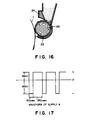
- a waveform diagram of the bias voltage is shown in Figure 7. More specifically, the latent image-bearing member and the toner-carrying member are disposed with a spacing of 50 - 500 microns, preferably 50 - 180 microns.
- the frequency is 1.5 - 10 kHz, preferably 4 - 8 kHz.
- the development time T A is set to satisfy 10 ⁇ sec ⁇ TA 200 u.sec, preferably 30 ⁇ sec ⁇ A ⁇ 200 usec.
- the peeling (or reverse development) time T ⁇ is set to satisfy 100 ⁇ sec ⁇ D 500 u.sec, preferably 100 ⁇ sec ⁇ T D ⁇ 180 u.sec.
- the development voltage V A and the peeling voltage V D are set to satisfy V A > - 150 V, V D ⁇ 400 V, and V D - VA 800 V, preferably -150 V ⁇ V A ⁇ -200 V and 400 V ⁇ V D 450 V. According to this system, the jumping and attachment of toner particles onto non-image parts are prevented to improve the gradation characteristic and the high-reproducibility.
- Figure 8 illustrates a schematic view of toner flying in such a system.
- a toner in a development region which is formed at the closest part between a toner-carrying member and a latent image-bearing member, a toner is reciprocally moved between the toner-carrying member and the latent image-bearing member under application of an AC bias voltage between the toner-carrying member and the latent image-bearing member to be finally transferred and attached selectively to the surface of the latent image-bearing member corresponding to a latent image pattern to visualize the latent image.
- the duty ratio at this time is 50 %, and accordingly the development time and the reverse development time are the same.
- the above-mentioned two types of developing methods can be improved by applying a higher development side bias voltage while setting a short time therefor, so that it becomes possible to obtain images which have a high image density, are rich in gradation characteristic and are free from ground fog.
- the particle size distribution of the toner remaining in the developing apparatus was examined whereby the change in particle size distribution was observed as compared with that of the initial stage and the deterioration in image qualities was found to be caused by the change in particle size distribution of the toner due to selective consumption of toner in a particular particle size range.
- Requirement A To form a uniform coating layer of magnetic toner on a toner-carrying member.
- Requirement B To uniformly and effectively charge the magnetic toner triboelectrically. It has been hitherto tried to satisfy the requirements A and B in combination.
- a coating blade at the outlet of a toner container.
- a blade 24 comprising a magnetic material is disposed opposite to a magnetic pole N1 of a fixed magnet 23 enclosed within a toner-carrying member 22 to form ears of the toner along magnetic lines of force acting between the magnetic pole N1 and the magnetic blade 24 and cut the ears with the tip edge of the blade 24, thereby regulating the thickness of the resulting toner layer under the action of the magnetic force (e.g., as disclosed in JP-A-54 43037).
- the surface of a toner-carrying member is provided with an indefinite unevenness pattern as shown in Figure 14 by sand-blasting the surface with irregular-shaped particles, so as to always provide a uniform toner coating state for a long period of time.
- the entire surface of the toner-carrying member thus treated has minute cuttings or projections disposed at random.
- a developing apparatus using a toner-carrying member having such a specific surface state can result in deterioration of developing characteristics, such as fog and lower image density depending on the magnetic toner used. This is caused by occurrence of insufficiently charged toner particles in the magnetic toner leading to a lowering in electric charge of the toner layer. In some cases, other difficulties can be encountered, such as tailing, scattering, or instability of reproduction of thin lines.
- a developing method for achieving the requirements A and B in combination has been proposed (EP-A-0331425).
- the developing method uses a toner-carrying member having a surface subjected to blasting with definite-shaped particles in combination with a magnetic toner having a specific particle size distribution so as to be capable of forming a uniform toner coating layer for a long period.
- toner particles having a small particle size can be attached to the surface of the toner-carrying member because of an image force due to their high electric charge so that triboelectrification of the other particles can be hindered.
- the proportion of toner particles having insufficient charge is increased to cause a lowering in image density in some cases. This phenomenon is liable to be encountered particularly under the low-humidity condition.
- the above phenomenon is promoted when the toner on the toner-carrying member is not consumed, e.g., so as to provide a white ground image, and results in a decrease in image density.
- This phenomenon is alleviated to gradually restore an intended image density when the toner on the toner-carrying member is consumed, e.g., so as to provide a black image part.
- toner-carrying member memory or “sleeve memory”.
- the toner-carrying member memory can be solved by the consumption of the toner on the toner-carrying member as is understood from the mechanism of the occurrence.
- the toner-carrying member memory is alleviated for each one rotation of the toner-carrying member. Accordingly, a light degree of toner- carrying member memory disappears from the developed image after one rotation, but a serious toner-carrying member memory repeatedly appears in several developed images.
- a toner-carrying member subjected to blasting with definite-shaped particles has better charge-imparting ability than a toner-carrying member subjected to blasting with indefinite-shaped particles and is thus more advantageous in charging a toner.
- such a toner-carrying member is liable to excessively charge a toner to result in the toner-carrying member memory.
- the above-mentioned latent image-bearing member may comprise a photosensitive member for electrophotography, which may for example comprise Se, CdS, an organic photoconductor (OPC), and amorphous silicon (hereinafter called "a-Si").
- a photosensitive member for electrophotography which may for example comprise Se, CdS, an organic photoconductor (OPC), and amorphous silicon (hereinafter called "a-Si").
- a-Si has high sensitivities over the entirely of visible wavelength regions so that it is also applicable to a semiconductor laser and color image formation. Moreover, it has a high surface hardness as represented by a Vickers hardness of 1500 -2000 and is expected to have a long life as represented by a copying or printing durability of 10 6 sheets or more which is several times that of a CdS photoconductor. Further, a-Si also has a sufficient heat-resistance which is satisfactory for practical use of electrophotographic copying machines.
- an a-Si photosensitive member is said to have a surface dark (part) potential which depends on the thickness.
- the surface dark potentials of commercially used photosensitive members are required to be 500 V at the minimum for CdS photosensitive members and 600 -800 V for Se photosensitive members and OPC photosensitive members.
- An a-Si photosensitive member is required to have a large thickness for accomplishing such potentials in view of variation in various characteristics and possible decrease in sensitivity due to changes in environmental conditions.
- a thin a-Si photosensitive member In order to use a thin a-Si photosensitive member, it is necessary to adopt a developing method capable of development at a low potential. While use of a thin a-Si photosensitive member is satisfactory in respects of production cost, capacity and photosensitive performances, it results in a lower surface potential, and attachment of impurities onto the surface under a high humidity condition which leads to lower photosensitive characteristics and image flow in the resultant image.
- a practical a-Si provides a surface dark potential of about 400 V, and the stably applicable potential is about 300 V. In such a case of a low developing contrast of 300 V between the light and dark parts, it is extremely difficult to obtain a sufficient density of solid black by an ordinary developing method.
- the developing contrast in normal development refers to the absolute value of a difference obtained by subtracting a developing potential from an average dark part potential over a photosensitive member.
- a novel developing method capable of developing a low potential latent image is expected.
- An object of the present invention is to provide an image forming method and an image forming apparatus using a nonsymmetric developing bias voltage having solved the above-mentioned problems.
- a more specific object of the present invention is to provide an image forming method and an image forming apparatus which are excellent in durability and are capable of stably providing toner images having a high image density and free from white ground fog even ina long period of continuous use.
- Another object of the present invention is to provide an image forming method and an image forming apparatus capable of providing toner images which are rich in gradation characteristic and excellent in resolution and thin line reproducibility.
- Still another object of the present invention is to provide an image forming method and an image forming apparatus capable of stably providing toner images having a high image density even under a low humidity condition.
- Another object of the present invention is to provide an image forming method and an image forming apparatus wherein a magnetic toner is uniformly applied on a toner-carrying member and is also uniformly charged stably and not excessively or not insufficiently, so that the flying of the magnetic toner is made more effective.
- Another object of the present invention is to provide an image forming method and an image forming apparatus wherein the toner-carrying member memory is prevented or suppressed.
- Another object of the present invention is to provide an image forming method and an image forming apparatus wherein an electrostatic latent image formed on an a-Si photosensitive member is effectively developed.
- Another object of the present invention is to provide an image forming method and an image forming apparatus which are capable of providing a sufficient image even by using an a-Si photosensitive member having a low surface potential.
- Another object of the present invention is to provide an image forming method and an image forming apparatus wherein even a small potential contrast on an a-Si photosensitive member can be faithfully developed to provide a gradational image.
- Another object of the present invention is to provide an image forming method and an image forming apparatus wherein a delicate latent image formed on an a-Si photosensitive member is faithfully developed to provide a toner image excellent in thin line reproducibility and resolution.
- a further object of the present invention is to provide an image forming method and an image forming apparatus by a high developing speed and a high durability are realized by using an a-Si photosensitive member.
- an image forming method comprising:
- an image forming apparatus comprising: a latent image-bearing member for holding an electrostatic image thereon, a toner-carrying member for carrying a layer of a magnetic toner thereon, a toner vessel for holding the magnetic toner to be supplied to the toner-carrying member, a toner layer-regulating member for regulating the magnetic toner layer on the toner-carrying member, and a bias application means for applying an alternating bias voltage comprising a DC bias voltage and an unsymmetrical AC bias voltage in superposition between the toner-carrying member and the latent image-bearing member, wherein the latent image-bearing member and the toner-carrying member are disposed with a prescribed gap therebetween at a developing station; the toner layer-regulating means is disposed to regulate the magnetic toner layer on the toner-carrying member in a thickness thinner than the prescribed gap; the magnetic toner comprises a binder resin and magnetic powder and has a particle size
- a magnetic toner having a small charge attached in a small account to a non-image part on the latent image-bearing member (a toner particle resulting in fog) due to toner scattering, etc., is returned to the toner-carrying member under the action of the peeling voltage because of a weak image force, whereby fog is prevented.
- the apparatus includes a latent image-bearing member 1 which can be a latent image-bearing member (so-called photosensitive member), such as a rotating drum, for electrophotography; an insulating member, such as a rotating drum, for electrostatic recording; photosensitive paper for the Electrofax; or electrostatic recording paper for direct. electrostatic recording.
- An electrostatic latent image is formed on the surface of the latent image-bearing member 1 by a latent image forming mechanism or latent image forming means (not shown) and the latent image-bearing member is rotated in the direction of an indicated arrow.
- the apparatus also includes a developing apparatus which in turn includes a toner container 21 (hopper) for holding a toner and a rotating cylinder 22 as a toner-carrying member (hereinafter, also called “(developing) sleeve”) in which a magnetic field-generating means 23, such as a magnetic roller, is disposed.
- a toner container 21 hopper
- rotating cylinder 22 as a toner-carrying member
- a magnetic field-generating means 23 such as a magnetic roller
- Almost a right half periphery (as shown) of the developing sleeve 22 is disposed within the hopper 21 and almost a left hand periphery of the sleeve 22 is exposed outside the hopper.
- the sleeve 22 is axially supported and rotated in the direction of an indicated arrow.
- a doctor blade 24 as a toner layer regulating means is disposed above the sleeve 22 with its lower edge close to the upper surface of the sleeve 22.
- a stirrer 27 is disposed for stirring the toner within the hopper 21.
- the sleeve 22 is disposed with its axis being in substantially parallel with the generatrix of the latent image-bearing member 1 and opposite to the latent image-bearing member 1 surface with a slight gap therefrom.
- the surface moving speed (circumferential speed) of the sleeve 22 is substantially identical to or slightly larger than that of the latent-image bearing member 1.
- a DC voltage and an AC voltage are applied in superposition by an alternating bias voltage application means So and a DC bias voltage application means Si.
- the image forming method of the present invention not only the magnitude of the alternating bias electric field but also the application time thereof are controlled as well as a triboelectric charge adapted to the controlling developing bias voltage. More specifically, as for the alternating bias, the frequency thereof is not changed, but the development-side bias component is increased while the application time thereof is shortened and correspondingly the reverse development-side bias component is suppressed low while the application time thereof is prolonged, thus changing the duty ratio of the alternating bias voltage.
- the development-side bias (voltage) component refers to a voltage component having a polarity opposite to that of a latent image potential (with reference to the toner-carrying member) on the latent image-bearing member (in other words, the same polarity as the toner for developing the latent image), and the reverse development-side bias (voltage) component refers to a voltage component having a polarity opposite to the latent image.
- Figure 2 shows an example of an unsymmetrical alternating bias voltage comprising an AC bias voltage and a DC bias voltage.
- Figure 2 refers to a case where a toner having a negative charge is used for developing a latent image having a positive potential with reference to the toner-carrying member.
- the part a refers to a development-side bias component and the part b refers to a reverse development-side bias component.
- the magnitudes of the development-side component and the reverse development-side component are denoted by the absolute values of Va and Vb.
- the duty factor of the alternating bias voltage is denoted, except for its DC bias voltage component, as follows: wherein t a denotes the duration of a voltage component with a polarity for directing the toner toward the latent image-bearing member of one cycle of an AC bias voltage (constituting the developing side bias component a ), and t b reversely denotes the duration a voltage component with a polarity for peeling the toner from the latent image-bearing member of the AC bias voltage (constituting the reverse development-side.bias component b ).
- the DC bias voltage may be set between the dark part potential and the light part potential of the latent image-bearing member and may preferably be set so that the alternating bias voltage comprising the AC bias voltage and the DC bias voltage has a voltage component of the same polarity as the development-side bias component which is larger in amplitude than a component of the same polarity as the reverse development-side bias component respectively with respect to the ground level.
- Almost a right half periphery of the developing sleeve 22 always contacts the toner within the hopper 21, and the toner in the vicinity of the sleeve surface is attached to and held on the sleeve surface under the action of a magnetic force exerted by the magnetic field-generating means 23 disposed in the sleeve 23 and/or an electrostatic force.
- the magnetic toner layer held on the sleeve is leveled into a thin toner layer T 1 having a substantially uniform thickness when it passes by the position of the doctor blade 24.
- the charging of the magnetic toner is principally effected by triboelectrification through friction with the sleeve surface and the toner stock in the vicinity of the sleeve surface caused by the rotation of the sleeve 22.
- the thin magnetic toner layer on the developing sleeve 22 rotates toward the latent image-bearing member 1 as the sleeve rotates and passes a developing station or region 1..1
- the magnetic toner in the magnetic toner layer on the developing sleeve 22 flies under the action of DC and AC voltages applied between the latent image-bearing member 1 and the developing sleeve 22 and reciprocally moves between the latent image-bearing member 1 surface and the developing sleeve 22 surface in the developing region A.
- the magnetic toner on the developing sleeve 22 is selectively moved and attached to the latent image-bearing member 1 surface corresponding to a latent image potential pattern thereon to successively form a toner image T 2 .
- the developing sleeve surface having passed by the developing region A and having selectively consumed the magnetic toner thereon rotates back into the toner stock in the hopper 21 to be supplied again with the magnetic toner, whereby the thin toner layer T 1 on the developing sleeve 22 is continually moved to the developing region A when developing steps are repeatedly effected.
- a problem accompanying such a developing scheme is that a developing performance can be decreased due to an increased force of attachment of magnetic toner particles in the vicinity of the developing sleeve surface in some cases.
- the magnetic toner and the sleeve always cause friction with each other as the developing sleeve 22 rotates, so that the magnetic toner is gradually caused to have a large charge, whereby the electrostatic force (Coulomb's force) between the magnetic toner and the sleeve is increased to weaken the force of flying of the magnetic toner.
- the magnetic toner is stagnant in the vicinity of the sleeve to hinder the triboelectrification of the other toner particles, thus resulting in a decrease in developing characteristic. This particularly occurs under a low humidity condition or through repetition of developing steps. Due to a similar mechanism, the above-mentioned toner-carrying member memory occurs.
- the force of flying the magnetic toner from the sleeve toward the latent image-bearing member 1 is required to provide an acceleration so as to cause the magnetic toner to sufficiently reach the latent image surface under the action of an AC bias electric field. If the mass of a toner particle is denoted by m, the force is given by If the charge of the toner particle is denoted by q, the distance from the sleeve is denoted by d and the alternating bias electric field is denoted by the force is roughly given by Thus, the force of toner reaching the latent image surface is determined by a balance between the electrostatic attraction force with the sleeve and the electric field force.
- toner particles of 5 microns or smaller which are liable to gather in the vicinity of the developing sleeve can also be flied if the electric field is increased.
- the development-side bias voltage is simply increased, the toner is caused to fly toward the latent image side regardless of the latent image pattern. This tendency is strong for toner particles of 5 microns or smaller, thus being liable to cause ground fog.
- the ground fog can be prevented by increasing the reverse development-side voltage, but if the alternating electric field acting between the latent image-bearing member 1 and the developing sleeve 22 is increased, a discharge is directly caused between the latent image-bearing member 1 and the sleeve 22 to remarkably impair the image quality.
- the toner attached not only to the non-latent image part but also to the latent image pattern (image part) is caused to be peeled.
- magnetic toner particles of 8 - 12.7 microns having a relatively small image force to the latent image-bearing member are liable to be removed so that the coverage on the latent image part becomes poor to cause image defects, such as disturbance of a developed pattern, deterioration of gradation characteristic and line-reproducibility and liability of hollow image (white dropout of a middle part of an image).
- toner particles of 5 microns or smaller on the sleeve which constitute an essential component for improving the image quality can be effectively caused to fly and reciprocally move. As a result, it has become possible to suppress the decrease in image density and toner-carrying member memory.
- the reverse development-side bias electric field is provided with a sufficiently long duration while the magnitude thereof is suppressed, a force for peeling an excessive toner attached to outside the latent image pattern from the latent image-bearing member 1 is given so that ground fog can be prevented.
- Figure 3 shows an example of the alternating bias voltage waveform used in the present invention.
- the reverse development-side bias electric field is weak but the duration thereof is prolonged so that the effective force for peeling from the latent image-bearing member remains identical.
- the toner image attached to the toner image is not disturbed so that a good image with a gradation characteristic is attained.
- the sleeve used in the present invention is excellent in triboelectricity-imparting ability to uniformly charge the magnetic toner of the invention, so that a good developing performance is attained under application of the alternating electric field for development according to the invention.
- a high-density image free from fog can be obtained with high image qualities, such as excellent gradation characteristic, resolution and thin-line reproducibility.
- Toner particles of 5 microns or smaller are effectively consumed by the development-side bias to accomplish a high image quality and do not stick to the surface of even a specific developing sleeve as described below the present invention, so that the decrease in image density of toner-carrying member memory is not liable to occur.
- Toner particles of 8 - 12.7 microns are sufficiently used for development under the action of the development-side bias voltage to accomplish high image density and gradation characteristic but are not peeled from the latent image-bearing member under the action of the reverse development-side bias, so that middle dropout and disturbance of line images can be obviated.
- the developing bias voltage Under the action of the developing bias voltage according to the present invention, when ears formed of a toner fly and the tips of the ears touch the latent image-bearing member, the toner particles in the neighborhood of the ear tips, particles of a small particle size and particles having a large charge are attached to the latent image-bearing member for effecting development because of the image force, whereas the particles constituting the trailing ends or particles having a small charge are returned to the toner-carrying member under the action of the reverse development-side bias.
- the ears tend to be broken so that difficulties such as tailing and scattering due to ears can be alleviated.
- the developing sleeve and the magnetic toner used in the invention tend to form uniform and small ears, so that the effect is enhanced.
- the magnetic toner having a specific particle size distribution or the sleeve having a specific surface shape according to the invention are successively supplied to latent images under the action of the developing bias according to the invention, so that shortage of toner coverage is not caused.
- the development-side-bias electric field is so strong as to cause toner particles near the sleeve surface fly, so that toner particles having a large charge are more intensively used for development of a latent image pattern.
- toner particles having a large charge are firmly attached onto even a weak latent image pattern due to an electrostatic force, so that an image having a sharp edge can be obtained at a high resolution.
- magnetic toner particles of 5 microns or smaller effective for realizing a high quality image is effectively used to provide a good image.
- a satisfactory development may be effected for a gap of from 0.1 mm to 0.5 mm between the developing sleeve 22 and the latent image-bearing member 1 while 0.3 mm was representatively used in Examples described hereinafter. This is because a higher development-side bias allows a larger gap between the developing sleeve and the latent image-bearing member than in the conventional developing method.
- the peak-to-peak voltage of the alternating bias voltage may preferably be 1.0 kV or higher and 2.0 kV or lower.
- the leakage can of course change depending on the gap between the developing sleeve 22 and the latent image-bearing member 1.
- the frequency of the alternating bias may preferably be 1.0 kHz to 5.0 kHz. If the frequency is below 1.0 kHz, a better gradation can be attained but it becomes difficult to dissolve the ground fog. This is presumably because, in such a lower frequency region where the frequency of the reciprocal movement of the toner is smaller, the force of pressing toner onto the latent image-bearing member due to the development-side becomes excessive even onto a non-image part, so that a portion of toner attached onto the non-image part cannot be completely removed by the peeling force due to the reverse development-side bias electric field.
- the reverse development-side bias electric field is applied before the toner sufficiently contacts the latent image-bearing member, so that the developing performance is remarkably lowered. In other words, the toner per se cannot response to such a high frequency electric field.
- a frequency of the alternating bias electric field in the range of 1.5 kHz to 3 kHz provided an optimum image quality.
- the duty factor of the alternating bias electric field waveform according to the present invention may be substantially below 50 %, preferably be a value satisfying: 10 % duty factor 40 %. If the duty factor is above 40 %, the above-mentioned defects become noticeable to fail to achieve the improvement in image quality according to the present invention. If the duty factor is below 10 %, the response of the toner to the alternating bias electric field becomes poor to lower the developing performance.
- the duty factor may optimally be in the range of 15 to 35 % (inclusive).
- the alternating bias waveform may for example be in the form of a rectangular wave, a sine-wave, a saw-teeth wave or a triangular wave.
- a magnetic toner having a particle size distribution ranging from 0.5 microns to 30 microns was used for developing latent images on a photosensitive member having various surface potential contrasts ranging from a large potential contrast at which a majority of toner particles were readily used for development, through a half tone contrast and to a small potential contrast at which a slight portions of toner particles were used for development. Then, the toner particles used for developing the latent images were recovered from the photosensitive member for measurement of the particle size distribution. As a result, it was found that the proportion of magnetic toner particles of 8 microns or smaller, particularly magnetic toner particles of 5 microns or smaller, was increased. It was also found that latent images were faithfully developed without enlargement and at a good reproducibility when magnetic toner particles of 5 microns or smaller most suitable for development were smoothly supplied to latent images on the photosensitive member.
- a characteristic of the magnetic toner according to the present invention is that it contains 12 % by number or more of magnetic toner particles having a particle size of 5 microns or smaller. Hitherto, it has been difficult to control the charge imported to magnetic toner particles of 5 microns or smaller so that these small particles are liable to be charged excessively. For this reason, magnetic toner particles of 5 microns or smaller have been considered to have a strong image force onto a developing sleeve and are firmly attached to the sleeve surface to hinder triboelectrification of the other particles and cause insufficiently charged toner particles, thus resulting in roughening of images and a decrease in image density. Thus, it has been considered necessary to decrease magnetic toner particles of 5 microns or smaller.
- magnetic toner particles of 5 microns or smaller constitute an essential component for providing images of a high quality.
- toner particles of 5 microns or smaller are effectively caused to fly and prevented from sticking onto the sleeve surface.
- toner particles of 8 - 12.7 microns constitute 33 % by number or less. This is related with the above-mentioned necessity of the magnetic toner particles of 5 microns or smaller. Magnetic toner particles of 5microns or smaller are able to strictly cover and faithfully reproduce a latent image, but a latent image per se has a higher electric field intensity at the peripheral edge than the middle or central portion. As a result, toner particles are attached to the central portion in a smaller thickness than to the peripheral part, so that the inner part is liable to be thin in density. This tendency is particularly observed by magnetic toner particles of 5 microns or smaller.
- the magnetic toner having a particle size distribution satisfying the relationship according to the present invention accomplishes a better developing performance.
- a large N/V value is understood to mean that a large proportion of particles smaller than 5 microns are present with a broad particle size distribution
- a small N/V value is understood to mean that particles having a particle size in the neighborhood of 5 microns is present in a large proportion and particles smaller than that are present in a small proportion.
- a further better thin-line reproducibility and high resolution are accomplished when the N/V is in the range of 2.1 - 5.82 and further satisfy the above formula relationship.
- Magnetic toner particles of 16 microns or larger is suppressed to be not more than 2.0 % by volume. The fewer, the better.
- the particle size distribution of the magnetic toner used in the present invention is described more specifically below.
- Magnetic toner particles of 5 microns or smaller may be contained in a proportion of 12 % by number or more, preferably 12 - 60 % by number, further preferably 17 - 60 % by number, of the total number of particles. If the content of the magnetic toner particles of 5microns or smaller is below 12 % by number, a portion of the magnetic toner particles effective for providing a high image quality is few and particularly, as the toner is consumed during a continuation of copying or printing-out, the effective component is preferentially consumed to result in an awkward particle size distribution of the magnetic toner and gradually deteriorates the image quality.
- magnetic toner particles of 5 microns or smaller constitute an essential component for stabilizing the volume-average particle size of the magnetic toner on the developing sleeve during a successive image forming or copying operation.
- magnetic toner particles of 5 microns or smaller which are most suitable for development are consumed in a large amount, so that if the amount of the particles of this size is small, the volume-average of the magnetic toner on the sleeve is gradually increased and the mass on the sleeve M/S (mg/cm 2 ) is increased to make the uniform toner coating on the sleeve difficult.
- the content of the particles in the range of 8 - 12.7 microns is 33 % by number or less, further preferably 1 - 33 % by number. Above 33 % by number, the image quality becomes worse, and excess of toner coverage is liable to occur, thus resulting in an increased toner consumption. Below 1 % by number, it becomes difficult to obtain a high image density in some cases.
- the volume-average particle size at this time may be 4 - 10 microns.
- k ⁇ 4.5 magnetic toner particles of 5.0 microns or below are insufficient, and the resultant image density, resolution and sharpness decrease.
- fine toner particles in a magnetic toner which have conventionally been considered useless, are present in an appropriate amount, they are effective for achieving closest packing of toner in development and contribute to the formation of a uniform image free of coarsening. Particularly, these particles fill thin-line portions and contour portions of an image, thereby to visually improve the sharpness thereof. If k ⁇ 4.5 in the above formula, such component becomes insufficient in the particle size distribution, and the above-mentioned characteristics become poor.
- the amount of magnetic toner particles having a particle size of 16 microns or larger is 2.0 % by volume or smaller, preferably 1.0 % by volume or smaller, more preferably 0.5 % by volume or smaller. If the above amount is larger than 2.0 % by volume, these particles not only are liable to impair thin-line reproducibility but also can cause transfer failure images because coarse particles of 16 microns or larger are present after development on the photosensitive member in the form of projections above a thin toner layer to irregularize the delicate contact between the photosensitive member and a transfer paper by the. medium of the toner layer, thus resulting in change in transfer conditions leading to transfer failure.
- toner particles of 16 microns or larger cannot be flied onto the latent image-bearing member unless they are sufficiently charged, so that they are liable to remain on the toner-carrying member to cause a change in particle size distribution, binder the triboelectrification of other toner particles to lower the developing performance, and disturb the shape toner ears, thus causing deterioration of image qualities.
- magnetic toner particles of 5 microns or smaller In contrast with the magnetic toner particles of 5 microns or smaller, magnetic toner particles of 16 microns or larger are relatively less consumable in successive image formation. Accordingly, if they are contained in a proportion exceeding 2.0 % by volume, the volume-average particle size of the magnetic toner on the sleeve is gradually increased to result in an increase in M/S on the sleeve, which is not desirable.
- the magnetic toner used in the present invention may have a volume-average particle size of 4 - 10 microns, preferably 4 - 9 microns. This valve cannot be considered separately from the above-mentioned factors.
- volume-average particle size is below 4 microns, a problem of insufficient toner coverage on a transfer paper is liable to be caused for an image having a high image area proportion, such as a graphic image. This is considered to be caused by the same reason as the problem that the interior of a latent image is developed at a lower density than the contour. If the volume-average particle size exceeds 10 microns, a good resolution may not be obtained and the particle size distribution is liable to be changed on continuation of copying to lower the image quality even if it is satisfactory at the initial stage of copying.
- the magnetic toner used in the present invention having a specific particle size distribution is capable of faithfully reproducing even thin lines of a latent image formed on the photosensitive member and is also excellent in reproducibilities in dot images, such as halftone dots and digital dots to provide images excellent in gradation and resolution. Further, even when the copying or printing out is continued, it is possible to maintain a high image quality and well develop a high-density image with a less toner consumption than a conventional magnetic toner, so that the magnetic toner of the present invention is advantageous in respect of economical factor and reduction in size of a copying machine or printer main body.
- the developing method applied to the magnetic toner according to the present invention allows more effective accomplishment of the above effect.
- the particle size distribution of a toner is measured by means of a Coulter counter in the present invention, while it may be measured in various manners.
- Coulter counter Model TA-II (available from Coulter Electronics Inc.) is used as an instrument for measurement, to which an interface (available from Nikkaki K.K.) for providing a number-basis distribution, and a volume-basis distribution and a personal computer CX-1 (available from Canon K.K.) are connected.
- a 1 %-NaCI aqueous solution as an electrolytic solution is prepared by using a reagent-grade sodium chloride.
- a reagent-grade sodium chloride For example, ISOTON®-II (available from Coulter Scientific Japan K.K.) may be used therefor.
- a surfactant preferably an alkylbenzenesulfonic acid salt
- 2 to 20 mg of a sample is added thereto.
- the resultant dispersion of the sample in the electrolytic liquid is subjected to a dispersion treatment for about 1 - 3 minutes by means of an ultrasonic disperser, and then subjected to measurement of particle size distribution in the range of 2 - 40 microns by using the above-mentioned Coulter counter Model TA-II with a 100 micron-aperture to obtain a volume-basis distribution and a number-basis distribution.
- TA-II Coulter counter Model TA-II with a 100 micron-aperture
- the magnetic toner used in the present invention satisfies the condition represented by the formula (1) below: wherein R is a number satisfying the relation of 4 R 10 and representing the volume-average particle size of the magnetic toner, and Q represents the absolute value of the triboelectric charge of the magnetic toner on a developing sleeve. It is further preferred that the condition represented by the following formula (2) is satisfied:
- the electric charge data of a toner layer on a developing sleeve described herein are based on valves measured by the so-called suction-type Faraday cage method. More specifically, according to the Faraday cage method, an outer cylinder of a Faraday cage is pressed against the developing sleeve and the toner disposed on a prescribed area of the sleeve is sucked to be collected by the filter on the inner cylinder, whereby the toner layer weight in a unit area may be calculated from the weight increase of the filter. Simultaneously, the charge accumulated in the inner cylinder which is isolated from the exterior is measured to obtain the charge on the sleeve.
- the binder resin constituting the magnetic toner used in the present invention may for example comprise the following materials.
- styrene styrene derivatives, such as o-methylstyrene, m-methylstyrene, p-methylstyrene, p-methoxystyrene, p-phenylstyrene, p-chlorostyrene, 3,4-dichlorostyrene, p-ethylstyrene, 2,4-dimethylstyrene, p-n-butylstyrene, p-tert-butylstyrene, p-n-hexylstyrene, p-n-octylstyrene, p-n-nonylstyrene, p-n-decylstyrene, and p-n-dodecylstyrene; ethylenically unsaturated mono
- binder resin may include: polyesters, polyurethane, epoxy resin, polyvinylbutyral, rosin, modified rosin, terpene resin, phenolic resin, aliphatic or alicyclic hydrocarbon resins, aromatic petioleum resins, haloparaffins, paraffin wax, etc. These may be used singly or in mixture.
- styrene-type resins acrylic resins, and polyester resins are particularly preferred as binder resins.
- the binder resin may further preferably be a crosslinked vinyl polymer, a crosslinked vinyl copolymer or a mixture of these polymers, obtained by using a crosslinking agent as follows:
- crosslinking agents may preferably be used in a proportion of about 0.01 - 5 wt. parts, particularly about 0.03 - 3 wt. parts, per 100 wt. parts of the other monomer components.
- aromatic divinyl compounds particularly, divinylbenzene
- diacrylate compounds connected with a chain including an aromatic group and an ether bond may suitably be used in a toner resin in view of fixing characteristic and anti-offset characteristic. It is preferred that at least one of these compounds is used for constituting the binder resin.
- the binder resin for constituting a toner to be used for a pressure fixing system may comprise a low-molecular weight polyethylene, low-molecular weight polypropylene, ethylene-vinyl acetate copolymer, ethylene-acrylate copolymer, higher fatty acid, polyamide resin or polyester resin. These resins may be used singly or in mixture.
- the magnetic toner according to the present invention comprises a magnetic material, examples of which may include: iron oxide and iron oxide containing another metal oxide, such as magnetite, maghemite, and ferrite; metals, such as Fe, Co and Ni, alloys of these metals with other metals, such as Al, Co, Cu, Pb, Mg, Ni, Sn, Zn, Sb, Be, Bi, Cd, Ca, Mn, Se, Ti, W and V, and mixtures of these materials.
- iron oxide and iron oxide containing another metal oxide such as magnetite, maghemite, and ferrite
- metals such as Fe, Co and Ni, alloys of these metals with other metals, such as Al, Co, Cu, Pb, Mg, Ni, Sn, Zn, Sb, Be, Bi, Cd, Ca, Mn, Se, Ti, W and V, and mixtures of these materials.
- the magnetic material may preferably have an average particle size of 0.1 - 2 microns, and magnetic properties under application of 10 k Oersted, inclusive of a coercive force of 20 - 150 Oersted, a saturation magnetization of 50 - 200 emu/g, particularly 50 - 100 emu/g, and a remanence of 2 - 20 emu/g.
- the magnetic toner according to the present invention may preferably be used by adding a charge control agent internally or externally.
- the charge control agent may be known positive charge controllers, examples of which may include: nigrosine and its modified products, e.g., with aliphatic acid metal salts, quarternary ammonium salts, diorganotin oxides and diorganotin borates. These may be used singly or in combination of two or more species. Among these, nigrosine type compounds and quarternary ammonium salts may be particularly preferred.
- a positive charge control agent a homopolymer of a nitrogen-containing monomer represented by the formula: wherein R, denotes H or CH 3 , and R 2 and R 3 respectively denote an alkyl group capable of having a substituent; or a copolymer of the nitrogen-containing monomer with another polymerizable monomer as described above, such as styrene, an acrylate or a methacrylate.
- the resultant nitrogen-containing homopolymer or copolymer can also function as a part or all of the binder resin.
- a negative charge control agent which may be known one such as carboxylic acid derivatives or their metal salts, alkoxylates, organic metal complexes, and chelate compounds.
- These negative charge control agents may be used singly or in mixture of two or more species.
- acetylacetone metal complex, salicyclic acid metal complexes alkylsalicylic acid metal complexes, dialkylsalicyclic acid metal complexes, naphthoic acid metal complexes, and monoazometal complexes may be particularly suitably used.
- the toner according to the invention can contain an arbitrary appropriate pigment or dye as a colorant as desired.
- the magnetic material may also function as a colorant.
- the toner of the invention may further contain. an additive, as desired.
- an additive may include: lubricants, such as Teflon, polyvinylidene fluoride, and aliphatic acid metal salts; abrasives, such as cerium oxide, strontium titanate, and silicon carbide; fluidity-imparting agents, such as colloidal silica, alumina, and surface-treated silica and surface-treated alumina which have been treated with a surface-treating agent, such as silicone oil, various modified silicone oils, silane coupling agent, and silane coupling agent having a functional group; caking preventing agents; conductivity-imparting agents, such as carbon black and tin oxide; and fixing aids, such as low-molecular weight polyethylene.
- lubricants such as Teflon, polyvinylidene fluoride, and aliphatic acid metal salts
- abrasives such as cerium oxide, strontium titanate, and silicon carbide
- waxy substance such as low-molecular weight polyethylene, low-molecular weight polypropylene, microcrystalline wax, carnauba wax or sasol wax in a proportion of 0.5 to 5 wt. % to the toner according to the present invention in order to provide an improved releasability of the time of hot roller fixation.
- the toner used in the present invention may preferably be prepared by a method in which toner constituents are sufficiently blended in a mixer such as a ball mill and then kneaded well in a hot kneading means, such as a kneader or extruder, mechanically crushed and classified.
- a binder resin solution containing other components dispersed therein is spray-dried; a polymerization method wherein prescribed ingredients are dispersed in a monomer constituting a binder resin and the mixture is emulsified, followed by polymerization of the monomer to provide a polymer; etc.
- the toner used in the present invention can be in the form of a microcapsule toner comprising a core material and a shell material.
- a latent image-bearing member a photosensitive member comprising an a-Si photosensitive layer on a conductive substrate in applying the bias conditions according to the present invention.
- Such an a-Si photosensitive member can be provided with a lower charge injection-prevention roller below the photosensitive layer so as to prevent charge injection from the substrate.
- a photosensitive drum for holding a negatively charged electrostatic image can be prepared by forming a photosensitive layer with hydrogenated (i.e., hydrogen-containing) a-Si, a lower charge injection-preventing layer with hydrogenated a-Si doped with phosphorus, and an upper charge injection-preventing layer with hydrogenated a-Si doped with boron.
- hydrogenated i.e., hydrogen-containing
- a photosensitive drum for holding a positively charged electrostatic image can be prepared by forming a lower charge injection-preventing layer with hydrogenated a-Si doped with boron and a surface protective layer with an amorphous film comprising silicon, carbon and hydrogen (hereinafter called a-SiC film).
- An a-Si photosensitive member is generally excellent in heat resistance and abrasion resistance and is thus excellent in durability. Accordingly, the image forming method according to the present invention is advantageous for realization of a high-speed image forming apparatus. Further, it is possible to form a latent image faithful to an original image so that it is advantageous in realizing a high image quality in an image forming apparatus such as a copying machine.
- An Se photosensitive member and an OPC photosensitive member can cause deterioration of the photosensitive layer during a continuous use due to white reflection light, laser light and mechanical action to result in difficulties, such as decrease in photoconductivity and chargeability and increase in dark decay, so that they can fail to show sufficient electrophotographic performances in some cases.
- difficulties such that a sufficient dark potential can not be attained, it becomes impossible to lower the light part potential to a necessary level, and it becomes difficult to obtain an appropriate potential contrast or a latent image potential corresponding to an original.
- an insufficient density, fog and loss of gradation can occur.
- an a-Si photosensitive member capable of always maintaining a constant latent image potential is advantageous and such as a-Si photosensitive member can be applied to a high-speed machine without problem.
- an Se photosensitive member and an OPC photosensitive member can cause a disturbance in thin or fine latent images for the above-mentioned reason.
- the magnetic toner used in the present invention is capable of faithfully develop even thin latent images so that such a disturbance in latent image can be reflected in a developed image, thus being disadvantageous in delicate expression of thin lines and dots.
- an a-Si photosensitive member does not cause a disturbance in latent image so that the above-mentioned problems are not caused. The problems are also pronounced at a higher process speed.
- the magnetic toner used in the present invention has a large specific surface area, so that it has a tendency to cause a frequency contact to accelerate the abrasion of the photosensitive member when applied to a high-speed machine. Se and OPC photosensitive members are particularly liable to be abraded to promote the problem.
- an a-Si photosensitive member has a high hardness so that it is not concerned with such a problem.
- an AC bias voltage is controlled so that the magnitude of the developing-side bias electric field is increased and the duration thereof is shortened without charging the entire frequency of the AC bias voltage.
- the reverse development-side bias electric field is suppressed to be low and the duration thereof is increased, whereby the duty ratio of the AC bias voltage is controlled.
- toner particles of 5 microns or smaller on the sleeve which constitute an essential component for providing an improved image quality are effectively flied reciprocally to fully develop a latent image on an a-Si photosensitive member and prevent the sticking thereof onto the sleeve surface, whereby the decrease in image density and toner-carrying member memory are suppressed.
- the reverse-development side electric field is suppressed to be low, the duration thereof is sufficiently prolonged, so that an excess of toner attached to outside a latent image pattern on an a-Si photosensitive member is supplied with a peeling force from the latent image-bearing member 1 to suppress the ground fog.
- the reverse development-side electric field is suppressed to be low, so that toner particles of 8 - 12.7 microns constituting an essential component for toner coverage are not peeled.
- the reverse development-side bias electric field is suppressed to be low, the duration thereof is made longer, so that the effecting peeling force from the latent image-bearing member is ensured.
- the toner image attached to a latent image pattern is not disturbed, whereby a good image quality with gradation can be realized.
- the development-side bias electric field of an AC bias voltage is intensified to fly a portion of the toner present in the vicinity of the sleeve, so that such a portion of the toner in the vicinity of the sleeve and having a large charge is more intensively attached to a latent image pattern.
- a portion of the toner having a large charge is attached because of a large electrostatic force, whereby an image having an edge sharpness and a good resolution can be obtained, and magnetic toner particles of 5 microns or smaller which are an effective component for realizing a high image quality are effectively utilized to provide an extremely good image quality.
- a latent image on an a-Si photosensitive member has a low surface potential but has a large capacitance, so that the charge thereof is large. Accordingly, the magnetic toner according to the present invention is small in particle size and has a large charge, so that it is firmly attached to the latent image. The toner thus attached to a latent image part having a potential to be developed (image part) is not affected by the exterior and the image thereof is not disturbed.
- a fog toner even on an a-Si photosensitive member can be peeled by the developing bias according to the present invention.
- the magnetic toner is effectively flied under application of the above-mentioned specific bias voltage, so that a high image quality can be stably attached for a long period and the image quality is stable even under a continual use in a high-speed machine.
- the above-mentioned effect of the present invention can be remarkably exhibited if the development is performed under a small difference between the light part potential and the dark part potential of 250 - 400 V, preferably 250 - 350 V.
- the developing sleeve may preferably have a surface unevenness comprising sphere-traced concavities.
- the surface state can be obtained by blasting with definite shaped particles.
- the definite-shaped particles may preferably be spherical or spheroidal particles having a substantially smoothly curved surface and having a ratio of longer axis/shorter axis of 1 - 2, preferably 1 - 1.5, further preferably 1 - 1.2.
- the definite-shaped particles may for example be various solid spheres or globules, such as those of metals such as stainless steel, aluminum, steel, nickel and bronze, or those of ceramic, plastic or glass beads, respectively, having a specific particle size.
- the plurality of sphere-traced concavities on the sleeve surface may preferably have a diameter R of 20 to 250 microns If the diameter R is smaller than 20 microns, the soiling with a magnetic toner component is increased. On the other hand, a diameter R of over 250 microns is not preferred because the uniformity of toner coating on the sleeve is lowered.
- the definite-shaped particles used in blasting of the sleeve surface may preferably have a diameter of 20 - 250 microns.
- the definite shaped particles can have a particle size distribution as far as the above-mentioned R and the pitch P and roughness d of the sleeve surface as described hereinbelow are satisfied.
- the pitch P and the surface roughness d of the unevenness on a sleeve surface are based on measured values of roughness of the sleeve obtained by using a micro-surface roughness meter (commercially available from, e.g., Taylor-Hopson Co., and Kosaka Kenkyusho K.K.), and the surface roughness d is expressed in terms of a 10 point-average roughness (Rz) (JIS B 0601).
- Figure 13 shows an example of a surface section curve, from which a portion with a standard length I is taken.
- an average. line is drawn as shown in Figure 13, and then two lines each parallel with the average line are taken, one passing through a third highest peak (M 3 ) and the other passing through a third deepest valley or bottom (V 3 ).
- the 10 point-average roughness (R z or d ) is measured as the distance between the two lines in the unit of microns (micro-meters), and the standard length I is taken as 0.25 mm.
- the pitch P of the roughness on the sleeve surface may preferably be 2 to 100 microns.
- a pitch P of less than 2 microns is not preferred because the soiling of the sleeve with toner component is increased.
- a pitch P in excess of 100 microns is not preferred because the uniformity of toner coating on the sleeve is lowered.
- the surface roughness d of the roughness on the sleeve surface may preferably be 0.1 to 5 microns.
- a roughness d in excess of 5 microns is not preferred because an electric field is liable to be concentrated at uneven portions to cause disturbance in images in a system wherein an alternating voltage is applied between the sleeve and the latent image-holding member to cause jumping of the magnetic toner from the sleeve side onto the latent image surface.
- a roughness d of less than 0.1 micron is not preferred because the uniformity of toner coating on the sleeve is lowered.
- the definite-shaped blasting particles are larger than the indefinite-shaped blasting particles, preferably with the former being 1 - 20 times, particularly 1.5 - 9 times, the latter.
- a developing sleeve obtained by blasting with indefinite-shaped particles is referred to as Sleeve A
- a developing sleeve obtained by blasting with definite-shaped particles is referred to as Sleeve B
- a developing sleeve obtained by blasting with both indefinite-shaped particles and definite-shaped particles is referred to as Sleeve C.
- the roughness states of the respective sleeves thus obtained are represented by schematic views including Figure 14 (Sleeve A for comparison), Figure 11 (Sleeve B according to the invention) and Figure 12 (Sleeve C according to the invention).
- Sleeve A and Sleeve C are excellent.
- Sleeve B is somewhat inferior. This may be attributable to a factor that a surface with a sharp roughness is more suitable regarding conveying ability.
- Sleeve B and Sleeve C are excellent, and Sleeve B is particularly excellent. This is because a smoother sleeve surface has a more effective triboelectrification ability.
- toners on Sleeve B and Sleeve C are uniformly triboelectrically charged to be stably provided with a sufficient charge.
- This liability is more pronounced for Sleeve B, which can cause toner-coating irregularity because of an excessive charge in some cases.
- Sleeve B and Sleeve C are excellent in balance of toner coating stability and triboelectric charge-imparting ability.
- Sleeve C is particularly excellent in this respect.
- a developing sleeve is coated with magnetic toner particles forming ears (chains of magnetic toner particles formed under a magnetic field).
- the developed image quality can be affected by the shape of ears.
- a long ear and/or a thick ear can lead to image defects, such as tailing, scattering and collapsion, thus resulting in lowered resolution and thin-line reproducibility.
- the ear formation is affected by amount of charge and size of toner particles. For example, if toner particles are uniformly and sufficiently charged, ears having uniform length and thickness are formed to provide an improved image quality.
- the magnetic toner used in the present invention having a specific particle size distribution forms ears which are thin, short and dense (per unit area), thus being effective for improving the image quality.
- toner particles are ununiformly charged to contain insufficiently charged toner particles, this not only leads to fog but also disturbs ear formation to result in a mixture of long, short, thick and thin ears, thereby lowering the image quality.
- Sleeve A there are formed sharp projections on the surface, so that the toner particles contact the sleeve surface less frequently to result in poorly charged particles and disturbed ears, thus leading to adverse effects to the image quality.
- the increase in charge of toner particles at the initial stage is slow to provide sparse ears and can cause low image density and fog at the initial stage.
- the toner layer is not provided with a sufficient charge without any increase to provide a continually low density state in some cases. From also this point, it is also rare for Sleeve A to cause a toner coating failure due to excessive charge, thus providing a toner coating stability.
- Sleeve B and Sleeve C In the cases of Sleeve B and Sleeve C, they have smooth surfaces, so that triboelectrification between the toner particles and the sleeve is effectively performed to provide the toner with a uniform and sufficient charge, thus forming uniform and dense ears to provide a high image quality.
- the increase in charge of toner particles in quick so that a high density image free from fog is obtained from the initial stage.
- they are excellent in triboelectric charge-imparting ability they are liable to excessively charge a toner.
- the magnetic toner used in the present invention has the tendency so that, unless small particles having a high charge are effectively consumed at the time of development, they stick to the vicinity of the sleeve to cause the above-mentioned difficulties of decrease in density and toner-carrying member memory.
- Sleeve B has a particularly large charge imparting ability to provide toner particles with a large triboelectric charge, so that the above difficulties are liable to be caused.
- toner particles can be locally attached and abnormally dense ears are formed to cause a sleeve coating irregularity. This is particularly pronounced when toner particles of 16 microns or larger are much.
- Sleeve C sharp and fine projections formed by blasting with indefinite-shaped particles are depressed by blasting with definite-shaped particles to be provided with a moderately smooth surface, so that the charge-imparting ability is improved and a toner can be effectively charged triboelectrically. Further, as the roughness given by the blasting with indefinite-shaped particles remains to a certain extent, the toner-conveying ability is retained to effect a uniform toner coating. Further, excessive triboelectrification is prevented and thus difficulties accompanying the excessive charge are alleviated with respect to decrease in image density and toner-carrying member memory or prevented with respect toner coating irregularity.
- the effect of improved image quality by using the magnetic toner according to the present invention is promoted by formation of more uniform ears on the toner-carrying member.
- a characteristic of the magnetic toner according to the present invention is that it has a volume-average particle size of 4 - 10 microns.
- a developing sleeve (Sleeve B) according to the present invention has a specific surface unevenness comprising a plurality of sphere-traced concavities.
- the developing sleeve showed a somewhat inferior performance in forming a uniform magnetic toner coating layer compared with a developing sleeve (Sleeve A) having a surface unevenness formed by blasting with indefinite-shaped particles in a case where a toner having a volume-average particle size exceeding 11 microns was used in a specific environment.
- Sleeve B By using a magnetic toner having a specific particle size distribution, Sleeve B provided a toner coating stability comparable to that of Sleeve C. However, Sleeve B still showed a somewhat inferior toner coating stability than Sleeve C when a toner having a higher chargeability was used.
- thin-line reproducibility was evaluated in the following manner.
- An original of a thin line image having a width of accurately 100 microns is copied under suitable copying conditions to provide a sample copy for measurement.
- the line width of the toner image on the copy is measured on a monitor of Luzex 400 Particle Analyzer.
- the line width is measured at several points along the length of the thin line toner image so as to provide an appropriate average value in view of fluctuations in width.
- the value of thin line reproducibility (%) is calculated by the following formula:
- the resolution was evaluated in the following manner.
- An original sheet having 10 original line images each comprising 5 lines spaced from each other with an identical value for line width and spacing is provided.
- the 10 original images comprise the 5 lines at pitches of 2.8, 3.2, 3.6, 4.0, 4.5, 5.0, 5.6, 6.3, 7.1, 8.0. 9.0 and 10.0 lines/mm, respectively.
- the original sheet is copied under suitable conditions to obtain a sample copy on which each of the ten line images is observed through a magnifying glass and the maximum number of lines (lines/mm) of an image in which the lines can be discriminated from each other is identified as a resolution measured. A larger number indicates a higher resolution.
- a stainless steel sleeve (SUS 304) in the form of a 32 mm-dia. cylinder containing a magnet therein was provided, and the surface thereof was blasted with indefinite-shaped A1 2 0 3 particles #400 (particle size: 35 - 45 microns) under the conditions of a blast nozzle diameter of 7 mm, a distance of 150 mm, an air pressure of 3.5 kg/cm 2 , and a blasting time of 60 sec., whereby Sleeve No. 1 (Reference Example) was obtained.
- FIG. 14 A partial surface section of Sleeve No. 1 is schematically shown as Figure 14.
- Sleeve No. 2 (present invention) was prepared in the same manner as in Production Example 1 except that the blasting was effected by using definite shaped glass (true spheres having a long axis/short axis ratio of substantially 1.0) of #300 (53 - 62 microns).
- the surface concavities on the surface of Sleeve No. 2 showed an unevenness pitch P of 33 microns originated from the diameter R of 53 - 62 microns of the definite shaped particles and a surface roughness d of 2.0 microns.
- FIG. 11 A partial surface section of Sleeve No. 2 is schematically shown as Figure 11.
- Sleeve No. 3 (present invention) was prepared. by further blasting the surface of Sleeve No. 1 prepared in Production Example 1 with definite-shaped glass beads (true sphere) of #100 (150 - 180 microns) under the same blasting conditions as in Production Example 1 except that the air pressure was changed to 3.0 kg/cm2.
- a partial surface section of Sleeve No. 3 is schematically shown as Figure 12.
- Sleeve No. 4 (present invention) was prepared by further blasting the surface of Sleeve No. 1 prepared in Production Example 1 with definite-shaped glass beads (true sphere) of #200 (70 - 90 microns) under the same blasting conditions as in Production Example 1 except that the blasting time was changed to 30 sec.
- Sleeve No. 5 (present invention) was prepared in the same manner as in Production Example 1 except that the blasting was effected by using definite shaped glass (true spheres) of #100 (150 - 180 microns).
- the surface concavities on the surface of Sleeve No. 5 showed an unevenness pitch P of 52 microns originated from the diameter R of 150 - 180 microns of the definite shaped particles and a surface roughness d of 2.2 microns.
- Sleeve No. 6 (present invention) was prepared by further blasting the surface of Sleeve No. 1 prepared in Production Example 1 with the definite shaped particles (#300) used in Production Example 2 under the same blasting conditions as in Production Example 1.
- a selenium photosensitive drum was used as the latent image-bearing member 1
- the gap a between the latent image-bearing member 1 and the developing sleeve (toner-carrying member) 22 was set at 0.3 mm
- the gap between the developing sleeve 22 and the magnetic doctor blade 24 was set at 0.25 mm to form a magnetic toner layer thickness of about 120 microns on the developing sleeve.
- the magnetic field given by the magnet roller 23 as measured on the sleeve surface was 1000 gauss at the N 1 pole, 1000 gauss at the 8 1 pole, 750 gauss at the N 2 pole and 550 gauss at the S 2 pole.
- a copying test was performed at a rate of 50 sheets (A4)/min.
- Examples of the developing power supply used in the image forming apparatus of the present invention are explained particularly regarding their waveforms of the AC electric field.
- the above ingredients were well blended in a blender and melt-kneaded at 150 °C by means of a two- axis extruder.
- the kneaded product was cooled, coarsely crushed by a cutter mill, finely pulverized by means of a pulverizer using jet air stream, and classified by a fixed-wall type wind-force classifier (DS-type Wind-Force Classifier, mfd. by Nippon Pneumatic Mfg. Co. Ltd.) to obtain a classified powder product.
- DS-type Wind-Force Classifier mfd. by Nippon Pneumatic Mfg. Co. Ltd.
- Ultra-fine powder and coarse power were simultaneously and precisely removed from the classified powder by means of a multi-division classifier utilizing a Coanda effect (Elbow Jet Classifier available from Nittetsu Kogyo K.K.), thereby to obtain negatively chargeable insulating black fine powder (magnetic toner).
- the particle size distribution of the magnetic toner is shown in Table 1 appearing hereinafter.
- the magnetic toner in this mixture state is referred to as Magnetic toner No. 1.
- BET value 200 m 2 /g
- Magnetic toner No. 2 The magnetic toner in this mixture state is referred to as Magnetic toner No. 2.
- Magnetic toner No. 3 comprising toner particles having a particle size distribution as shown in Table 1 in mixture with silica fine powder was prepared from the above ingredients otherwise in the same manner as in Toner Production Example 1.
- Magnetic toner No. 4 comprising toner particles having a particle size distribution as shown in Table 1 in mixture with silica fine powder was prepared from the above ingredients otherwise in the same manner as in Toner Production Example 2.
- Magnetic toners Nos. 5 and 6 comprising toner particles having particle size distributions shown in Table 1 respectively in mixture with silica fine powder were prepared from the coarsely crushed product in Toner Production Example 1 under different fine pulverization and classification conditions otherwise in the same manner as in Toner Production Example 1.
- Example 5 a slight coating irregularity was observed on the sleeve corresponding to a non-image part, but no irregularities were observed in toner images even in repetition of development.
- a developing bias with a duty factor of 50 % was used. Tailing and toner carrying member memory were observed to provide inferior results in respects of gradation and resolution compared with Example 1.
- the present invention provides excellent effects as follows:
- a-Si photosensitive drums were prepared by means of a high-frequency plasma CVD apparatus by using gases of SiH 4 , H 2 , CH 4 , PH 3 , B 2 H 6 , GeH4, etc., according to the glow discharge process.
- an a-Si photosensitive drum as described above was used as the latent image-bearing member 1, the gap a between the latent image-bearing member 1 and the developing sleeve 22 was set at 0.3 mm, and the gap between the developing sleeve 22 and the magnetic doctor blade 24 was set at 0.25 mm to form a magnetic toner layer thickness of about 120 microns on the developing sleeve.
- the magnetic field given by the magnet roller 23 as measured on the sleeve surface was 1000 gauss at the N 1 pole, 1000 gauss at the S 1 pole, 750 gauss at the N 2 pole and 550 gauss at the S 2 pole.
- a copying test was performed at a rate of 80 sheets (A4)/min.
- the above ingredients were well blended in a blender and melt-kneaded at 150 °C by means of a two- axis extruder.
- the kneaded product was cooled, coarsely crushed by a cutter mill, finely pulverized by means of a pulverizer using jet air stream, and classified by a fixed-wall type wind-force classifier (DS-type Wind-Force Classifier, mfd. by Nippon Pneumatic Mfg. Co. Ltd.) to obtain a classified powder product.
- DS-type Wind-Force Classifier mfd. by Nippon Pneumatic Mfg. Co. Ltd.
- Ultra-fine powder and coarse power were simultaneously and precisely removed from the classified powder by means of a multi-division classifier utilizing a Coanda effect (Elbow Jet Classifier available from Nittetsu Kogyo K.K.), thereby to obtain negatively chargeable insulating black fine powder (magnetic toner).
- the particle size distribution of the magnetic toner is shown in Table 6 appearing hereinafter.
- the magnetic toner in this mixture state is referred to as Magnetic toner No. 7.
- Magnetic toner No. 8 comprising toner particles having a particle size distribution as shown in Table 6 in mixture with silica fine powder was prepared from the above ingredients otherwise in the same manner as in Toner Production Example 7.
- BET value 300 m 2 /g
- Magnetic toner No. 9 The magnetic toner in this mixture state is referred to as Magnetic toner No. 9.
- BET value 200 m 2 /g
- Magnetic toner No. 10 The magnetic toner in this mixture state is referred to as Magnetic toner No. 10.
- Magnetic toner No. 11 of positive chargeability comprising toner particles having a particle size distribution as shown in Table 6 in mixture with silica fine powder was prepared from the above ingredients otherwise in the same manner as in Toner Production Example 10.
- BET value 200 m 2 /g
- Magnetic toner No. 12 The magnetic toner in this mixture state is referred to as Magnetic toner No. 12.
- Magnetic toner No. 13 comprising toner particles having a particle size distribution shown in Table 6 in mixture with silica fine powder was prepared from the coarsely crushed product in Toner Production Example 7 under different fine pulverization and classification conditions otherwise in the same manner as in Toner Production Example 7.
- Magnetic toner No. 14 was prepared from the coarsely crushed product in Toner Production Example 10.
- the images were excellent in gradation characteristic and almost no toner-carrying member memory was observed.
- the difference between the dark part potential and the light part potential was set at +300 V in Examples 9 - 11 and at -300 V in Examples 12 - 14.
- the resultant images were good in respects of density and fog, but collaption of fine character images and inferior resolution were observed due to excessive toner coverage.
- Example 10 A similar copying test as in Example 10 was conducted except that an organic photoconductor (OPC) drum was used instead of Photosensitive drum No. 2 of a-Si. The results are also when in Table 9.
- OPC organic photoconductor
- Fog was observed at the time of copying 50,000 sheets, when the drum surface potential and the DC component of the developing bias voltage were reset so as to provide the same potential contrast as in the initial stage. On further copying, deterioration of image quality was observed compared with Example 10.
- Example 10 The image evaluation was conducted at the time of copying 100,000 sheets after resulting the potential contrast. At this time, the a-Si drum used in Example 10 was loaded to effect further image formation, whereby the same image quality as in Example 10 was obtained.
- the present invention provides excellent effects as follows:
- a copying test was conducted in the following manner by using an image forming apparatus as shown in Figure 1 and loaded with a selenium photosensitive drum.
- the above ingredients were well blended in a blender and melt-kneaded at 150 °C by means of a two- axis extruder.
- the kneaded product was cooled, coarsely crushed by a cutter mill, finely pulverized by means of a pulverizer using jet air stream, and classified by a fixed-wall type wind-force classifier (DS-type Wind-Force Classifier, mfd. by Nippon Pneumatic Mfg. Co. Ltd.) to obtain a classified powder product.
- DS-type Wind-Force Classifier mfd. by Nippon Pneumatic Mfg. Co. Ltd.
- Ultra-fine powder and coarse power were simultaneously and precisely removed from the classified powder by means of a multi-division classifier utilizing a Coanda effect (Elbow Jet Classifier available from Nittetsu Kogyo K.K.), thereby to obtain negatively chargeable insulating black fine powder (magnetic toner).
- the particle size distribution of the magnetic toner is shown in Table 10 appearing hereinafter.
- Copying tests were conducted similarly as in Example 15 except for using magnetic toners as shown in Table 10 which had been obtained by changing the amounts of the magnetic material and the charge control agent, controlling the fine pulverization and classification conditions to obtain particle size distribution as shown and changing the amount of silica fine powder added. The results are shown in Table 11.
- a magnetic toner prepared from the above ingredients otherwise in the same manner as in Example 15 showed a particle size distribution (except for the silica) as shown in Table 10.
- Example 15 Compared with the images in Example 15, the resultant images were inferior in gradation characteristic, somewhat inferior in resolution and thin-line reproducibility and accompanied with a some degree of white ground fog. Also toner carrying member memory was observed.
- Example 15 A copying test was conducted in the same manner as in Example 15 except for using a magnetic toner as shown in Table 10 which had been obtained from the coarsely crushed product in Example 15 by changing the fine pulverization and classification conditions to obtain a particle size distribution shown in Table 10. The results are shown in Table 11.
- a magnetic toner prepared from the above ingredients otherwise in the same manner as in Example 15 showed a particle size distribution shown Table 10 and provided results shown in Table 11 as a result of copying test which was conducted in the same manner as in Example 15.
- the resultant images showed a low image density because of hollow images (middle dropout) and showed unstable line thicknesses.
- a magnetic toner prepared from the above ingredients otherwise in the same manner as in Example 15 showed a particle size distribution shown Table 10 and provided results shown in Table 11 as a result of a copying test which was conducted in the same manner as in Example 15.
- Figure 15 shows a relationship between the volume-average particle size and the charge on the toner-carrying member (developing sleeve) of the magnetic toners tested in Examples and Comparative Examples.
- the present invention provides excellent effects as follows:
- An image forming apparatus is formed by disposing a latent image-bearing member for holding an electrostatic image thereon and a toner-carrying member for carrying a magnetic toner with a prescribed magnetic toner comprises a binder resin and magnetic powder and has a particle size distribution including 12 % by number or more of magnetic toner particles of 5 microns or smaller, 33 % by number or less of magnetic toner particles of 8 - 12.7 microns and 2 % by volume or less of magnetic toner particles of 16 microns or larger so as to provide a volume-average particle size of 4 - 10 microns.
- an alternating bias voltage comprising a DC voltage and an unsymmetrical AC voltage in superposition is applied between the toner-carrying member and the latent image-bearing member to provide an alternating bias electric field comprising a development-side voltage component and a reverse-development side voltage component.
- the development-side voltage component has a magnitude equal to or larger than that of the reverse development-side voltage component and a duration smaller than that of the reverse-development side voltage component, so that the magnetic toner on the toner-carrying member, particularly fine powdery fraction thereof effective for high-quality development, is effectively transferred to the latent image-bearing member to develop the electrostatic image thereon at the developing station.
Applications Claiming Priority (6)
| Application Number | Priority Date | Filing Date | Title |
|---|---|---|---|
| JP1249061A JPH0789237B2 (ja) | 1989-09-27 | 1989-09-27 | 画像形成方法及び画像形成装置 |
| JP249061/89 | 1989-09-27 | ||
| JP263848/89 | 1989-10-12 | ||
| JP1263848A JPH0711717B2 (ja) | 1989-10-12 | 1989-10-12 | 磁性トナー |
| JP316528/89 | 1989-12-07 | ||
| JP31652889 | 1989-12-07 |
Publications (3)
| Publication Number | Publication Date |
|---|---|
| EP0420197A2 true EP0420197A2 (fr) | 1991-04-03 |
| EP0420197A3 EP0420197A3 (en) | 1992-03-11 |
| EP0420197B1 EP0420197B1 (fr) | 1994-03-02 |
Family
ID=27333785
Family Applications (1)
| Application Number | Title | Priority Date | Filing Date |
|---|---|---|---|
| EP90118483A Expired - Lifetime EP0420197B1 (fr) | 1989-09-27 | 1990-09-26 | Méthode et appareil de formation d'images |
Country Status (3)
| Country | Link |
|---|---|
| US (1) | US5175070A (fr) |
| EP (1) | EP0420197B1 (fr) |
| DE (1) | DE69006997T2 (fr) |
Cited By (2)
| Publication number | Priority date | Publication date | Assignee | Title |
|---|---|---|---|---|
| EP0541113A1 (fr) * | 1991-11-08 | 1993-05-12 | Canon Kabushiki Kaisha | Révélateur à un composant pour développer des images électrostatiques et méthode de formation d'images |
| EP0575068A1 (fr) * | 1992-06-15 | 1993-12-22 | Konica Corporation | Dispositif de développement avec une électrode de contrôle |
Families Citing this family (19)
| Publication number | Priority date | Publication date | Assignee | Title |
|---|---|---|---|---|
| JPH0511582A (ja) * | 1991-02-05 | 1993-01-22 | Fuji Xerox Co Ltd | 電子複写機 |
| JP2812080B2 (ja) * | 1991-07-24 | 1998-10-15 | 日本ゼオン株式会社 | 非磁性一成分現像剤 |
| US5307127A (en) * | 1992-02-28 | 1994-04-26 | Canon Kabushiki Kaisha | Developing apparatus using one component toner with improved flowability |
| JP2899193B2 (ja) * | 1992-06-08 | 1999-06-02 | キヤノン株式会社 | 静電荷像現像用トナー及び画像形成方法 |
| JPH05346727A (ja) * | 1992-06-16 | 1993-12-27 | Fuji Xerox Co Ltd | 現像装置および現像剤担持体 |
| US5453768A (en) * | 1993-11-01 | 1995-09-26 | Schmidlin; Fred W. | Printing apparatus with toner projection means |
| JP3397484B2 (ja) * | 1994-12-16 | 2003-04-14 | キヤノン株式会社 | 画像形成装置、プロセスカートリッジ、現像剤容器及び現像剤補給容器 |
| US5832343A (en) * | 1995-04-03 | 1998-11-03 | Canon Kabushiki Kaisha | Toner supply method, toner accommodation container, process cartridge and electrophotographic image forming apparatus |
| JPH08272282A (ja) * | 1995-04-03 | 1996-10-18 | Canon Inc | 画像形成装置、プロセスカートリッジ及びトナーホッパー |
| DE69624610T2 (de) * | 1995-04-03 | 2003-09-18 | Canon Kk | Tonerbehälter und Prozesskassette |
| DE10007885B4 (de) | 1999-02-22 | 2016-08-18 | Kyocera Corp. | Bilderzeugungsverfahren und Bilderzeugungsvorrichtung |
| JP3984833B2 (ja) | 2001-01-16 | 2007-10-03 | キヤノン株式会社 | 現像剤担持体の再生方法 |
| JP3997065B2 (ja) | 2001-08-20 | 2007-10-24 | キヤノン株式会社 | プロセスカートリッジ及び画像形成装置 |
| US7223511B2 (en) | 2003-09-02 | 2007-05-29 | Canon Kabushiki Kaisha | Developer carrying member and developing method by using thereof |
| US7727619B2 (en) * | 2003-10-31 | 2010-06-01 | Canon Kabushiki Kaisha | Developer carrying member and developing apparatus |
| US20080124516A1 (en) * | 2004-03-19 | 2008-05-29 | Ngk Insulators, Ltd. | Method for Producing Porous Ceramic Structure |
| US20100040969A1 (en) * | 2008-08-12 | 2010-02-18 | Ligia Aura Bejat | Toner Formulations with Tribocharge Control and Stability |
| US10606181B2 (en) | 2013-12-27 | 2020-03-31 | Lexmark International, Inc. | Toner compositions including silica blends and method to make the same |
| US9217939B2 (en) | 2014-02-14 | 2015-12-22 | Lexmark International, Inc. | Toner formulations having improved toner usage efficiency and method to make the same |
Citations (4)
| Publication number | Priority date | Publication date | Assignee | Title |
|---|---|---|---|---|
| US4565438A (en) * | 1984-02-01 | 1986-01-21 | Xerox Corporation | Development system using electrically field dependent developer material |
| US4600295A (en) * | 1983-11-30 | 1986-07-15 | Canon Kabushiki Kaisha | Image forming apparatus |
| EP0331425A2 (fr) * | 1988-02-29 | 1989-09-06 | Canon Kabushiki Kaisha | Procédé et appareil de formation d'images |
| EP0331426A2 (fr) * | 1988-02-29 | 1989-09-06 | Canon Kabushiki Kaisha | Procédé et appareil de formation d'images |
Family Cites Families (26)
| Publication number | Priority date | Publication date | Assignee | Title |
|---|---|---|---|---|
| US2297691A (en) * | 1939-04-04 | 1942-10-06 | Chester F Carlson | Electrophotography |
| US3405682A (en) * | 1964-06-08 | 1968-10-15 | Xerox Corp | Xerographic development apparatus with web loading means to remove residual developer |
| US4071361A (en) * | 1965-01-09 | 1978-01-31 | Canon Kabushiki Kaisha | Electrophotographic process and apparatus |
| JPS4223910B1 (fr) * | 1965-08-12 | 1967-11-17 | ||
| US3776722A (en) * | 1966-04-22 | 1973-12-04 | M Cantarano | Electrophotographic method of imagewise particle transfer employing alternating modulated field |
| US3890929A (en) * | 1973-02-15 | 1975-06-24 | Xerox Corp | Xerographic developing apparatus |
| US3866574A (en) * | 1973-02-15 | 1975-02-18 | Xerox Corp | Xerographic developing apparatus |
| US3893418A (en) * | 1974-05-30 | 1975-07-08 | Xerox Corp | Xerographic developing apparatus |
| GB2081135B (en) * | 1977-09-10 | 1982-09-08 | Canon Kk | Developing apparatus for electrostatic image |
| JPS598831B2 (ja) * | 1977-09-10 | 1984-02-27 | キヤノン株式会社 | トナ−層形成装置 |
| CA1138723A (fr) * | 1978-07-28 | 1983-01-04 | Tsutomu Toyono | Methode et appreil de developpement pour transfert de revelateur par polarisation electrique |
| JPS5518657A (en) * | 1978-07-28 | 1980-02-08 | Canon Inc | Electrophotographic developing method |
| JPS5832377B2 (ja) * | 1978-07-28 | 1983-07-12 | キヤノン株式会社 | 現像装置 |
| JPS5518658A (en) * | 1978-07-28 | 1980-02-08 | Canon Inc | Electrophotographic developing method |
| JPS5832375B2 (ja) * | 1978-07-28 | 1983-07-12 | キヤノン株式会社 | 現像方法 |
| JPS5614242A (en) * | 1979-07-16 | 1981-02-12 | Canon Inc | Electrostatic developing method |
| JPS5766455A (en) * | 1980-10-11 | 1982-04-22 | Canon Inc | Development device |
| US4380966A (en) * | 1980-10-11 | 1983-04-26 | Canon Kabushiki Kaisha | Development apparatus |
| GB2145942B (en) * | 1983-08-05 | 1987-03-18 | Konishiroku Photo Ind | Developing latent eletrostatic images |
| JPS6073647A (ja) * | 1983-09-30 | 1985-04-25 | Canon Inc | 画像形成法 |
| JPS61190361A (ja) * | 1985-02-20 | 1986-08-25 | Toshiba Corp | 現像装置 |
| JPH07120109B2 (ja) * | 1986-09-30 | 1995-12-20 | 株式会社東芝 | 記録装置 |
| JPH0760273B2 (ja) * | 1987-10-26 | 1995-06-28 | キヤノン株式会社 | 磁性現像剤 |
| JP2763318B2 (ja) * | 1988-02-24 | 1998-06-11 | キヤノン株式会社 | 非磁性トナー及び画像形成方法 |
| US4904558A (en) * | 1988-03-08 | 1990-02-27 | Canon Kabushiki Kaisha | Magnetic, two-component developer containing fluidity improver and image forming method |
| US4992348A (en) * | 1988-06-28 | 1991-02-12 | Sharp Kabushiki Kaisha | Electrophotographic photosensitive member comprising amorphous silicon |
-
1990
- 1990-09-26 DE DE69006997T patent/DE69006997T2/de not_active Expired - Fee Related
- 1990-09-26 US US07/588,436 patent/US5175070A/en not_active Expired - Lifetime
- 1990-09-26 EP EP90118483A patent/EP0420197B1/fr not_active Expired - Lifetime
Patent Citations (4)
| Publication number | Priority date | Publication date | Assignee | Title |
|---|---|---|---|---|
| US4600295A (en) * | 1983-11-30 | 1986-07-15 | Canon Kabushiki Kaisha | Image forming apparatus |
| US4565438A (en) * | 1984-02-01 | 1986-01-21 | Xerox Corporation | Development system using electrically field dependent developer material |
| EP0331425A2 (fr) * | 1988-02-29 | 1989-09-06 | Canon Kabushiki Kaisha | Procédé et appareil de formation d'images |
| EP0331426A2 (fr) * | 1988-02-29 | 1989-09-06 | Canon Kabushiki Kaisha | Procédé et appareil de formation d'images |
Cited By (4)
| Publication number | Priority date | Publication date | Assignee | Title |
|---|---|---|---|---|
| EP0541113A1 (fr) * | 1991-11-08 | 1993-05-12 | Canon Kabushiki Kaisha | Révélateur à un composant pour développer des images électrostatiques et méthode de formation d'images |
| US5348829A (en) * | 1991-11-08 | 1994-09-20 | Canon Kabushiki Kaisha | Monocomponent-type developer for developing electrostatic image and image forming method |
| EP0575068A1 (fr) * | 1992-06-15 | 1993-12-22 | Konica Corporation | Dispositif de développement avec une électrode de contrôle |
| US5428428A (en) * | 1992-06-15 | 1995-06-27 | Konica Corporation | Developing device having a control electrode |
Also Published As
| Publication number | Publication date |
|---|---|
| DE69006997D1 (de) | 1994-04-07 |
| US5175070A (en) | 1992-12-29 |
| EP0420197A3 (en) | 1992-03-11 |
| EP0420197B1 (fr) | 1994-03-02 |
| DE69006997T2 (de) | 1994-06-23 |
Similar Documents
| Publication | Publication Date | Title |
|---|---|---|
| US5202731A (en) | Image forming apparatus having an alternating bias electric field | |
| EP0420197B1 (fr) | Méthode et appareil de formation d'images | |
| US5348829A (en) | Monocomponent-type developer for developing electrostatic image and image forming method | |
| US5849453A (en) | Image forming method including recycling of untransferred toner collected from image bearing member to developing means | |
| EP0947887A2 (fr) | Révélateur pour le développement d' images électrostatiques et procédé de production d' images | |
| US6873814B2 (en) | Developing device using a two-ingredient type developer and image forming apparatus including the same | |
| JP5094595B2 (ja) | 現像剤担持体及び現像装置 | |
| EP0844536B1 (fr) | Procédé de formation d'images | |
| EP0427275B1 (fr) | Toner pour le développement d'images électrostatiques, procédé de formation d'images et appareil de formation d'images | |
| EP1522902B1 (fr) | Agent de transport, agent de développement , méthode de développement, dispositif de développement et appareil électrophotographique de production d' images, unité de traitement et récipient de développateur | |
| EP0689100A1 (fr) | Véhiculeur pour électrophotographie, développeur du type à deux composants et procédé de formation d'images | |
| US4590140A (en) | Toner application method and treated magnetic particles for use therein | |
| US4554234A (en) | Toner application method and composition therefor | |
| EP0892319B1 (fr) | Appareil électrophotographique, procédé pour génération d'image et unité de traitement | |
| US5212524A (en) | Toner for developing electrostatic images, image forming method and image forming apparatus | |
| EP0371734B1 (fr) | Procédé de développement à brosse magnétique | |
| US4865936A (en) | Electrophotographic reversal development method using magnetic field and specified development gap | |
| JP2858005B2 (ja) | 現像方法 | |
| JP2872504B2 (ja) | 静電荷像現像用一成分系現像剤及び画像形成方法 | |
| JP2810527B2 (ja) | 画像形成方法及び画像形成装置 | |
| JP2003195639A (ja) | 現像装置および画像形成装置 | |
| US5506084A (en) | Magnetic developer and developing device using same | |
| JP3930944B2 (ja) | 画像形成方法 | |
| JP2001337487A (ja) | 静電荷像現像用トナー、その製造方法および画像形成装置 | |
| JPH073610B2 (ja) | 非晶質シリコン系光導電層の高速現像方法 |
Legal Events
| Date | Code | Title | Description |
|---|---|---|---|
| PUAI | Public reference made under article 153(3) epc to a published international application that has entered the european phase |
Free format text: ORIGINAL CODE: 0009012 |
|
| 17P | Request for examination filed |
Effective date: 19900926 |
|
| AK | Designated contracting states |
Kind code of ref document: A2 Designated state(s): DE FR GB IT NL |
|
| PUAL | Search report despatched |
Free format text: ORIGINAL CODE: 0009013 |
|
| AK | Designated contracting states |
Kind code of ref document: A3 Designated state(s): DE FR GB IT NL |
|
| 17Q | First examination report despatched |
Effective date: 19930405 |
|
| GRAA | (expected) grant |
Free format text: ORIGINAL CODE: 0009210 |
|
| AK | Designated contracting states |
Kind code of ref document: B1 Designated state(s): DE FR GB IT NL |
|
| REF | Corresponds to: |
Ref document number: 69006997 Country of ref document: DE Date of ref document: 19940407 |
|
| ITF | It: translation for a ep patent filed |
Owner name: SOCIETA' ITALIANA BREVETTI S.P.A. |
|
| ET | Fr: translation filed | ||
| PLBE | No opposition filed within time limit |
Free format text: ORIGINAL CODE: 0009261 |
|
| STAA | Information on the status of an ep patent application or granted ep patent |
Free format text: STATUS: NO OPPOSITION FILED WITHIN TIME LIMIT |
|
| 26N | No opposition filed | ||
| REG | Reference to a national code |
Ref country code: GB Ref legal event code: IF02 |
|
| PGFP | Annual fee paid to national office [announced via postgrant information from national office to epo] |
Ref country code: FR Payment date: 20060908 Year of fee payment: 17 |
|
| PGFP | Annual fee paid to national office [announced via postgrant information from national office to epo] |
Ref country code: NL Payment date: 20060917 Year of fee payment: 17 |
|
| PGFP | Annual fee paid to national office [announced via postgrant information from national office to epo] |
Ref country code: IT Payment date: 20060930 Year of fee payment: 17 |
|
| PG25 | Lapsed in a contracting state [announced via postgrant information from national office to epo] |
Ref country code: NL Free format text: LAPSE BECAUSE OF NON-PAYMENT OF DUE FEES Effective date: 20080401 |
|
| NLV4 | Nl: lapsed or anulled due to non-payment of the annual fee |
Effective date: 20080401 |
|
| REG | Reference to a national code |
Ref country code: FR Ref legal event code: ST Effective date: 20080531 |
|
| PG25 | Lapsed in a contracting state [announced via postgrant information from national office to epo] |
Ref country code: FR Free format text: LAPSE BECAUSE OF NON-PAYMENT OF DUE FEES Effective date: 20071001 |
|
| PGFP | Annual fee paid to national office [announced via postgrant information from national office to epo] |
Ref country code: GB Payment date: 20080911 Year of fee payment: 19 |
|
| PGFP | Annual fee paid to national office [announced via postgrant information from national office to epo] |
Ref country code: DE Payment date: 20080930 Year of fee payment: 19 |
|
| PG25 | Lapsed in a contracting state [announced via postgrant information from national office to epo] |
Ref country code: IT Free format text: LAPSE BECAUSE OF NON-PAYMENT OF DUE FEES Effective date: 20070926 |
|
| GBPC | Gb: european patent ceased through non-payment of renewal fee |
Effective date: 20090926 |
|
| PG25 | Lapsed in a contracting state [announced via postgrant information from national office to epo] |
Ref country code: DE Free format text: LAPSE BECAUSE OF NON-PAYMENT OF DUE FEES Effective date: 20100401 |
|
| PG25 | Lapsed in a contracting state [announced via postgrant information from national office to epo] |
Ref country code: GB Free format text: LAPSE BECAUSE OF NON-PAYMENT OF DUE FEES Effective date: 20090926 |