EP0416512A2 - Programmierbare Überwachungseinrichtung und Verfahren - Google Patents
Programmierbare Überwachungseinrichtung und Verfahren Download PDFInfo
- Publication number
- EP0416512A2 EP0416512A2 EP90116906A EP90116906A EP0416512A2 EP 0416512 A2 EP0416512 A2 EP 0416512A2 EP 90116906 A EP90116906 A EP 90116906A EP 90116906 A EP90116906 A EP 90116906A EP 0416512 A2 EP0416512 A2 EP 0416512A2
- Authority
- EP
- European Patent Office
- Prior art keywords
- display
- monitor unit
- elements
- unit according
- input
- Prior art date
- Legal status (The legal status is an assumption and is not a legal conclusion. Google has not performed a legal analysis and makes no representation as to the accuracy of the status listed.)
- Granted
Links
Images


Classifications
-
- G—PHYSICS
- G05—CONTROLLING; REGULATING
- G05B—CONTROL OR REGULATING SYSTEMS IN GENERAL; FUNCTIONAL ELEMENTS OF SUCH SYSTEMS; MONITORING OR TESTING ARRANGEMENTS FOR SUCH SYSTEMS OR ELEMENTS
- G05B19/00—Programme-control systems
- G05B19/02—Programme-control systems electric
- G05B19/04—Programme control other than numerical control, i.e. in sequence controllers or logic controllers
- G05B19/05—Programmable logic controllers, e.g. simulating logic interconnections of signals according to ladder diagrams or function charts
- G05B19/058—Safety, monitoring
-
- G—PHYSICS
- G05—CONTROLLING; REGULATING
- G05B—CONTROL OR REGULATING SYSTEMS IN GENERAL; FUNCTIONAL ELEMENTS OF SUCH SYSTEMS; MONITORING OR TESTING ARRANGEMENTS FOR SUCH SYSTEMS OR ELEMENTS
- G05B2219/00—Program-control systems
- G05B2219/10—Plc systems
- G05B2219/14—Plc safety
- G05B2219/14093—Display matrix of relay, contact symbols, select and show time
-
- Y—GENERAL TAGGING OF NEW TECHNOLOGICAL DEVELOPMENTS; GENERAL TAGGING OF CROSS-SECTIONAL TECHNOLOGIES SPANNING OVER SEVERAL SECTIONS OF THE IPC; TECHNICAL SUBJECTS COVERED BY FORMER USPC CROSS-REFERENCE ART COLLECTIONS [XRACs] AND DIGESTS
- Y10—TECHNICAL SUBJECTS COVERED BY FORMER USPC
- Y10S—TECHNICAL SUBJECTS COVERED BY FORMER USPC CROSS-REFERENCE ART COLLECTIONS [XRACs] AND DIGESTS
- Y10S715/00—Data processing: presentation processing of document, operator interface processing, and screen saver display processing
- Y10S715/961—Operator interface with visual structure or function dictated by intended use
- Y10S715/965—Operator interface with visual structure or function dictated by intended use for process control and configuration
Definitions
- the present invention relates to a programmable monitor unit which is used for writing programmable controller (PC) programs using a sequential functional chart (SFC) format.
- PC programmable controller
- SFC sequential functional chart
- present programmable monitors have several disadvantages.
- complex programs exhibiting a large number of converges become burdensome for the user to develop and cumbersome for the user to review.
- Fig. 11 represents a typical display 600 which shows the status of a plurality of contacts 822.
- the status of each of the contacts 822 is represented either by an on-state 826 or an off-state 828 condition in a time chart 825.
- Sampling times represented on line 832 can be only conventional sampling times such as microseconds, milliseconds, seconds or alternatively cycles.
- the display also shows the status of each channel 824. The status is typically represented in hexadecimal format 830 coordinated by the designated time periods 832.
- a conventional monitoring unit can only display the status of the contacts or channels individually.
- the status of transactions represented on a respective SFC diagram are not shown.
- the user To determine the SFC status, therefore, the user must analyze the channel and contact data and correlate that data with the SFC transaction.
- Such an effort becomes extremely burdensome for the programmer.
- it may ultimately limit that programmer's understanding of the program only to its microscopic effects rather than provide that user with an understanding of the program's effects at the transaction level.
- a programmable monitor unit which is adapted to display elements on a monitor screen.
- the monitor unit includes a display device which is comprised of a plurality of display areas, each respectively representing a single display element.
- the unit further includes a memory which is adapted to store a matrix of combined display elements which are defined respectively by individual standard display elements.
- the programmable monitor unit also includes a selecting device which enables an operator to respectively select combined display elements automatically such that the display produces a compressed image formed of combined display elements, each of which are represented in a single respective display area.
- a programmable monitor unit which includes a selecting device for designating transactions in a program.
- the monitor unit includes a system for checking the functional status or changes of transactions periodically during the execution of the program.
- the system includes a memory unit for storing the sensed functional status and changes in a table format based upon the operational cycles of the program. A display then displays the transactions identified in the table as a time chart that is defined by the operational cycles of the program.
- the method of the present invention is realized by displaying combined SFC elements to compress the display area.
- the method consists of the steps of storing a matrix of combined display element which are defined by respective fundamental display elements, selecting the combined display elements from the matrix and then displaying the combined elements wherein each respective combined display element is represented in a single display area of the monitor.
- the method of the present invention is carried out in a second embodiment by selecting designated transactions in a program and then checking the functional status and changes of the transactions periodically during the execution of the program.
- the functional status and changes are stored in a table format based upon the operational cycles and then displayed in a time- chart function defined by the operation cycles.
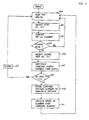
- Fig. 1 a flow chart representing the first embodiment of the invention.
- the programmable monitor for a PC can be used, for example, with a personal computer having a man-machine interface.
- the man-machine interface works in the following manner: A program is developed through the provision of inputs comprising SFC fundamental elements. These elements are inputted through a keyboard (not shown) whereby the PC then automatically draws the SFC symbol visually on the display. As a result, a program can be easily and quickly developed with a minimum of confusion and complication. As shown in Fig. 1, an example of an SFC display is shown.
- the display consists of a plurality of steps 102a, 102b, 102c, 102d and 102e, transitions 104a, 104b, 104c, 104d, 104e and 104f, and converges 106a and 106b.
- one converge 106a and one transition 104a can be compressed into a single display area 108 having the vertical dimension "a".
- two display elements such as a converge and transition, can be displayed along a vertical axis in the same display area 108.
- Fig. 1 represents prior art displays where each display element, such as a step, transition, converge or deconverge is restricted to a single display area 110a and 110b.
- the present invention provides significant screen compression over the arrangement of Fig. 5.
- the display in Fig. 1 represents 5 steps, 6 transitions and 2 converges, in other words 13 display elements in the same area.
- Fig. 5, on the other hand only displays 5 steps, 4 transitions and 2 converges, in other words 11 display elements within the same area.
- Such a savings can obviously be significant for complex SFC programs, especially large-scale programs.
- Fig. 2 a combination table is illustrated which is used, in accordance with the program of Fig. 3, to create the compressed display. More particularly, Fig. 2 illustrates a table 200 whose elements are defined by a first vertical column of display elements 202 and a second row of display elements 204. By use of the table, the display of two elements in a single display is achieved whereby previously only one element had been possible.
- the vertical column shows uncombined SFC fundamental elements that are to be designated first by a user.
- the horizontal row 204 represents the same SFC fundamental elements as in column 202.
- the row elements 204 are to be designated as a second input by the user such that the element would be displayed below the first entered element in a display area.
- Fig. 2 illustrates the various combinations 206 which can be combined by inputs 202 and 204.
- the symbol (-1) indicates that a logically impossible combination has been entered (i.e. two transitions).
- the selected combination element is then stored in an area of the computer memory.
- a flow chart illustrating the sequential operation of the first embodiment of the invention is shown.
- the system awaits a first key-in of the SFC input.
- the key-in occurs by selecting a function key, where the user then selects a numeric key to represent the part number of the selected SFC fundamental display element. For example, the user may input a "0-7" such that the system obtains a combination part number which is then referenced with the part number.
- the first keyed-in SFC symbol that corresponds to "0-7" is displayed. The monitor then waits to see if the user moves the cursor at step 303.
- the combined display element that represents the first and second display elements is selected from the table of Fig. 2 at step 305.
- the combined element is then tested at step 306 to determine if the combination is correct. If not, an alarm occurs at step 307 notifying the user of an error.
- the program then returns to step 300 to wait for a new first input from the user. However, if the combination is not in error, then the combined display is temporarily stored at step 309. At step 311, the combined display element replaces the first uncombined element on the display such that compression of the elements in a single display area results. The program then returns to step 300 to wait for another key entry.
- step 303 if an operator wishes to display each display element uncompressed in a single display area, he must move the cursor at step 303 such that the uncompressed display remains on the screen. The program then returns to step 300 to wait for another input.
- the first embodiment of the invention achieves the display of two consecutive elements in a single display area.
- the display of a higher quantity of SFC fundamental elements on the monitor screen can thus be achieved by compressing multiple elements into a single area.
- the user needs fewer key operations to program an SFC diagram on a screen.
- the invention also achieves a reduction in the blank areas on the screen and increases the number of SFC elements in a single screen area. All in all, operation is made more simple and display more efficient.
- SFC fundamental display elements other types of data can be used that are typically represented by a standard display format. These elements include but are not limited to CAD/CAM symbols, flow chart elements, architectural elements, chemical structures, graphs, tables, etc.
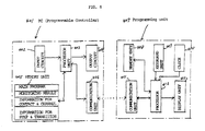
- Fig. 6 is a block diagram representing a second embodiment of the present invention.
- a programmable controller 401 comprises an input circuit 402, a processor unit 403 an output circuit 404, and a memory unit 405 connected respectively to the processor unit 403.
- the memory unit 405 is adapted to store control programs to monitor the status of various contacts in channels controlled and sensed by the programmable controller 401 and information relating to various steps and transitions.
- the processor 403 executes programs stored in the memory unit 405 and performs input/output control and communication related processing through the communication unit 406.
- the PC 401 is adapted to communicate with a programming unit 407.
- the program unit 407 consists of a memory unit 408 which is connected to a processor 412.
- the processor further receives information from a keyboard 409, and a clock 410.
- the processor is connected to a communication unit 411 which is adapted to communicate with the communication unit 406 of the PC 401.
- Information entered by the processor 412 is displayed on a display unit 413.
- the programming unit 407 is equipped to monitor functions so that debugging can easily be accomplished during programming.
- the monitoring operation involves periodically sensing the conditions and status of various contacts, channels, steps and transitions during a sampling period.
- the identity of these elements, as well as the sampling period(s) for these elements, are entered by an operator through the keyboard unit 409.
- the sampled data is stored in the memory 405 of the PC unit 401.
- a program step 501 or transition 503 each represent a single transaction such that various conditions that occur in the various contacts relating to a step or transition are defined by a single transaction element 501 or 503.
- SFC transaction format therefore, is that it provides an efficient expression of many individual status and conditions by means of generally used transaction symbols.
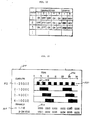
- a monitoring screen 600 can be used to represent the status and changes of transactions shown in the SFC program of Fig. 7 in a convenient manner. More particularly, in Fig. 8, a horizontal line 602 is provided to represent program operation cycles. For example, the cycles can be represented in units of time (such as 0-30 cycles) or in microseconds, milliseconds or seconds, etc. A time chart is illustrated wherein each row 603 represents a specific type of transaction. For example, 603-1 illustrates the contact number "13002". Row 603-2 represents the transition number "2.0" (see Fig. 7), while 603-3 and 603-4 each respectively represent a step and a transition point.
- each of the elements 603 is respectively represented in bar graph format whereby a status for each respective cycle is represented either as an on-state 604 or as an off-state 606.
- a lower portion of the display 600 represents the channel status 610 where two channels 612 and 614 are each represented at a particular point in the operational cycle.
- the status of each channel is represented in hexadecimal format since each channel consists of plural contacts that are not readily represented by a timing chart.
- the advantage of the timing chart shown in Fig. 8 is that it makes it easier for an operator to determine the status of an entire program being debugged rather a time chart representing the individual program lines or contact points as shown in Fig. 11. This is because the timing chart shown in Fig. 8 can be readily compared to and contrasted with the SFC flow chart elements shown in Fig. 7. Thus, the status of each step and transition displayed on the monitoring screen can be easily correlated together with the status of the contacts and channels in the SFC program.
- a functional flow chart of the operation of the programmable controller 401 in programming unit 407 is illustrated. More particularly, at a first step 701, the conditions of various contacts, channels that relate to steps, transitions are sampled and the status condition resulting therefrom are set in the programming unit 407. The results of the conditions are then communicated to the PC 401 through the communication units 411 and set respectively as shown in Fig. 6. During the transfer, the PC 401 continues to execute its various control programs and continues to control communication of the various input/output conditions.
- the above monitoring transactions provided from step 701 are executed along with the other functions.
- the PC 401 begins monitoring the transactions according to various conditions stored in the memory unit 405 at step 702.
- the memory unit 405 stores the status information in a time table as many times as the status checks are set by the programmer.
- monitoring stops at step 704 and the information stored in the memory unit 405 is transferred through communication units 406 and 411 to the programming unit at step 705.
- the data is then formatted to be represented in chart form as shown in Fig. 6 and then displayed on display unit 414 at step 706.
- That information is first input to a keyboard 409 of the programming unit 407 so that the PC 401 can then execute the monitoring operation and process the monitoring results so that those results are then displayed on a display unit 413 in a time chart format as shown in Fig. 8.
- Monitoring conditions are flexible and can be readily changed by the programmer. Various combinations of steps, transitions and individual contacts can thereby be respectively monitored. As a result, the present invention enables an operator to significantly reduce the debugging time of a program, since programmers can more readily debug a program on a step-by-step basis tied in with the program logic chart.
- the monitoring unit is thereby ultimately practical for monitoring SFC or any other kind of symbols representing discrete program functions
- Fig. 10 illustrates the operational cycle status of the various transaction elements (shown in the columns, rows or in the various channels).
- Fig. 10 is illustrative of the memory table organization used in the present invention. The data illustrated in Fig. 10 does not correlate with the data shown in Fig. 8 and 11.
- the advantage of the second embodiment of the invention is that a means to select designated transactions in a program such as steps and transitions and a means for easily checking the functional status of the transactions and transitions periodically during operation of the program is readily accomplished.
- the memory unit then stores the various functional status and changes in the time table, as shown in Fig. 10 and that information is then displayed in time chart fashion to the user.
- an operator realizes an efficient tool for debugging since he is able to define exactly those specific steps and transitions to be monitored.
- various types of information such as the status of contacts, of channels, of transitions or any other elements contemplated, can be monitored simultaneously. As a result, the debugging of specific parts of a program representing various types of elements can be done simultaneously, saving time and expense.
Applications Claiming Priority (4)
| Application Number | Priority Date | Filing Date | Title |
|---|---|---|---|
| JP22898589A JPH0391005A (ja) | 1989-09-04 | 1989-09-04 | プログラマブル・コントローラ用モニタ装置 |
| JP228985/89 | 1989-09-04 | ||
| JP238764/89 | 1989-09-14 | ||
| JP1238764A JP2570434B2 (ja) | 1989-09-14 | 1989-09-14 | Pc用プログラミング装置 |
Publications (3)
| Publication Number | Publication Date |
|---|---|
| EP0416512A2 true EP0416512A2 (de) | 1991-03-13 |
| EP0416512A3 EP0416512A3 (en) | 1991-11-27 |
| EP0416512B1 EP0416512B1 (de) | 1995-12-20 |
Family
ID=26528576
Family Applications (1)
| Application Number | Title | Priority Date | Filing Date |
|---|---|---|---|
| EP90116906A Expired - Lifetime EP0416512B1 (de) | 1989-09-04 | 1990-09-03 | Programmierbare Überwachungseinrichtung und Verfahren |
Country Status (4)
| Country | Link |
|---|---|
| US (1) | US5426730A (de) |
| EP (1) | EP0416512B1 (de) |
| AT (1) | ATE131945T1 (de) |
| DE (1) | DE69024287T2 (de) |
Cited By (1)
| Publication number | Priority date | Publication date | Assignee | Title |
|---|---|---|---|---|
| EP0551132A1 (de) * | 1992-01-10 | 1993-07-14 | Mitsubishi Denki Kabushiki Kaisha | Folgesteuerung die eine Fehlerkorrektur einschliesst und Verfahren dafür |
Families Citing this family (19)
| Publication number | Priority date | Publication date | Assignee | Title |
|---|---|---|---|---|
| JP2762893B2 (ja) * | 1993-04-02 | 1998-06-04 | 三菱電機株式会社 | プログラマブルコントローラ及びそのプログラマブルコントローラを用いたsfcプログラム実行方法 |
| JP3679844B2 (ja) * | 1995-11-09 | 2005-08-03 | ファナック株式会社 | シーケンス・プログラムの実行装置 |
| JP2001100817A (ja) * | 1999-09-30 | 2001-04-13 | Toyoda Mach Works Ltd | シーケンシャル・ファンクション・チャート式プログラマブル・コントローラにおける監視装置 |
| WO2001099338A1 (en) * | 2000-06-03 | 2001-12-27 | Threewin.Com Co., Ltd. | Method and apparatus for inputting secret information |
| US7287071B2 (en) * | 2000-09-28 | 2007-10-23 | Vignette Corporation | Transaction management system |
| KR100423742B1 (ko) * | 2000-10-31 | 2004-03-24 | 삼성중공업 주식회사 | 순차기능챠트에 의한 전용 제어 시스템 |
| US7310777B2 (en) * | 2002-10-18 | 2007-12-18 | Computer Associates Think, Inc. | User interface for viewing performance information about transactions |
| US8230359B2 (en) * | 2003-02-25 | 2012-07-24 | Microsoft Corporation | System and method that facilitates computer desktop use via scaling of displayed objects with shifts to the periphery |
| US8656006B2 (en) * | 2006-05-11 | 2014-02-18 | Ca, Inc. | Integrating traffic monitoring data and application runtime data |
| US7805510B2 (en) * | 2006-05-11 | 2010-09-28 | Computer Associates Think, Inc. | Hierarchy for characterizing interactions with an application |
| US8281281B1 (en) * | 2006-06-07 | 2012-10-02 | Pixar | Setting level of detail transition points |
| US9009680B2 (en) * | 2006-11-30 | 2015-04-14 | Ca, Inc. | Selecting instrumentation points for an application |
| US20080148242A1 (en) * | 2006-12-18 | 2008-06-19 | Computer Associates Think, Inc. | Optimizing an interaction model for an application |
| US7689610B2 (en) * | 2006-12-01 | 2010-03-30 | Computer Associates Think, Inc. | Automated grouping of messages provided to an application using string similarity analysis |
| US7917911B2 (en) * | 2006-12-01 | 2011-03-29 | Computer Associates Think, Inc. | Automated grouping of messages provided to an application using execution path similarity analysis |
| US20100268521A1 (en) * | 2009-04-17 | 2010-10-21 | Rainer Heller | Monitoring An Automation System |
| WO2010121097A1 (en) * | 2009-04-17 | 2010-10-21 | Siemens Aktiengesellschaft | Monitoring an automation system |
| US8706263B2 (en) * | 2010-06-08 | 2014-04-22 | Rockwell Automation Technologies, Inc. | Synchronization of execution of sequential function charts using transition groups |
| JP5724679B2 (ja) | 2011-06-29 | 2015-05-27 | 株式会社ジェイテクト | ブロック実行順表示装置 |
Citations (8)
| Publication number | Priority date | Publication date | Assignee | Title |
|---|---|---|---|---|
| US4445169A (en) * | 1980-06-13 | 1984-04-24 | The Tokyo Electric Co., Inc. | Sequence display apparatus and method |
| US4449180A (en) * | 1979-04-11 | 1984-05-15 | Hitachi, Ltd. | Sequence program inputting device |
| EP0198170A2 (de) * | 1985-02-16 | 1986-10-22 | Omron Tateisi Electronics Co. | Überwachungsschaltung |
| EP0224752A2 (de) * | 1985-11-07 | 1987-06-10 | Mitsubishi Denki Kabushiki Kaisha | Peripheriegerät für eine numerische Steuerung |
| US4697231A (en) * | 1985-06-21 | 1987-09-29 | F. J. Littell Machine Company | Machine control system |
| EP0251699A2 (de) * | 1986-06-24 | 1988-01-07 | Westinghouse Electric Corporation | Logikdiagrammübersetzer-Ausführeinheit |
| US4851985A (en) * | 1985-04-15 | 1989-07-25 | Logitek, Inc. | Fault diagnosis system for comparing counts of commanded operating state changes to counts of actual resultant changes |
| EP0362392A1 (de) * | 1988-01-08 | 1990-04-11 | Fanuc Ltd. | Rechnersimulierungssystem |
Family Cites Families (7)
| Publication number | Priority date | Publication date | Assignee | Title |
|---|---|---|---|---|
| US4315315A (en) * | 1971-03-09 | 1982-02-09 | The Johns Hopkins University | Graphical automatic programming |
| JPS56168263A (en) * | 1980-05-30 | 1981-12-24 | Hitachi Ltd | Program making device |
| US4546435A (en) * | 1980-06-24 | 1985-10-08 | Herbert Frank P | Graphic computer system and keyboard |
| US4656603A (en) * | 1984-03-01 | 1987-04-07 | The Cadware Group, Ltd. | Schematic diagram generating system using library of general purpose interactively selectable graphic primitives to create special applications icons |
| US4901221A (en) * | 1986-04-14 | 1990-02-13 | National Instruments, Inc. | Graphical system for modelling a process and associated method |
| US4984152A (en) * | 1987-10-06 | 1991-01-08 | Bell Communications Research, Inc. | System for controlling computer processing utilizing a multifunctional cursor with decoupling of pointer and image functionalities in space and time |
| US5001697A (en) * | 1988-02-10 | 1991-03-19 | Ibm Corp. | Method to automatically vary displayed object size with variations in window size |
-
1990
- 1990-09-03 EP EP90116906A patent/EP0416512B1/de not_active Expired - Lifetime
- 1990-09-03 AT AT90116906T patent/ATE131945T1/de not_active IP Right Cessation
- 1990-09-03 DE DE69024287T patent/DE69024287T2/de not_active Expired - Fee Related
-
1994
- 1994-01-31 US US08/188,749 patent/US5426730A/en not_active Expired - Lifetime
Patent Citations (8)
| Publication number | Priority date | Publication date | Assignee | Title |
|---|---|---|---|---|
| US4449180A (en) * | 1979-04-11 | 1984-05-15 | Hitachi, Ltd. | Sequence program inputting device |
| US4445169A (en) * | 1980-06-13 | 1984-04-24 | The Tokyo Electric Co., Inc. | Sequence display apparatus and method |
| EP0198170A2 (de) * | 1985-02-16 | 1986-10-22 | Omron Tateisi Electronics Co. | Überwachungsschaltung |
| US4851985A (en) * | 1985-04-15 | 1989-07-25 | Logitek, Inc. | Fault diagnosis system for comparing counts of commanded operating state changes to counts of actual resultant changes |
| US4697231A (en) * | 1985-06-21 | 1987-09-29 | F. J. Littell Machine Company | Machine control system |
| EP0224752A2 (de) * | 1985-11-07 | 1987-06-10 | Mitsubishi Denki Kabushiki Kaisha | Peripheriegerät für eine numerische Steuerung |
| EP0251699A2 (de) * | 1986-06-24 | 1988-01-07 | Westinghouse Electric Corporation | Logikdiagrammübersetzer-Ausführeinheit |
| EP0362392A1 (de) * | 1988-01-08 | 1990-04-11 | Fanuc Ltd. | Rechnersimulierungssystem |
Cited By (2)
| Publication number | Priority date | Publication date | Assignee | Title |
|---|---|---|---|---|
| EP0551132A1 (de) * | 1992-01-10 | 1993-07-14 | Mitsubishi Denki Kabushiki Kaisha | Folgesteuerung die eine Fehlerkorrektur einschliesst und Verfahren dafür |
| US5485366A (en) * | 1992-01-10 | 1996-01-16 | Mitsubishi Denki Kabushiki Kaisha | Sequence controller including error correction and method therefor |
Also Published As
| Publication number | Publication date |
|---|---|
| EP0416512A3 (en) | 1991-11-27 |
| DE69024287D1 (de) | 1996-02-01 |
| ATE131945T1 (de) | 1996-01-15 |
| EP0416512B1 (de) | 1995-12-20 |
| US5426730A (en) | 1995-06-20 |
| DE69024287T2 (de) | 1996-08-29 |
Similar Documents
| Publication | Publication Date | Title |
|---|---|---|
| EP0416512B1 (de) | Programmierbare Überwachungseinrichtung und Verfahren | |
| US4991076A (en) | Method and apparatus for creating custom displays for monitoring ladder logic programs | |
| US5325522A (en) | Apparatus and method for communicating between devices trough use of a real time data base | |
| US5530942A (en) | Graphic and text interactive user interface for a program execution analyzer | |
| US4736340A (en) | Processor generating control programs for a programmable controller | |
| US5889669A (en) | Programmable controller allowing an external peripheral device to monitor an internal operation state of a CPU unit | |
| US4661899A (en) | Numerical control system | |
| JP2653346B2 (ja) | プログラマブル・コントローラ | |
| EP0362392A1 (de) | Rechnersimulierungssystem | |
| JP3167245B2 (ja) | プログラマブルコントローラ動作状態監視装置 | |
| JPS61249108A (ja) | 数値制御装置における加工モニタ方式 | |
| US6992644B1 (en) | Peripheral device of a programmable controller and monitoring method of the peripheral device | |
| JP3356662B2 (ja) | プロセスデータ収集方法およびプログラム式表示装置 | |
| JPH051888B2 (de) | ||
| Zhang et al. | Online PLC monitoring and network administering system for steel tube mill | |
| JPS6051722B2 (ja) | シ−ケンスコントロ−ラの命令検索方式 | |
| JPH02253305A (ja) | Pcの信号トレース方式 | |
| JPS62281014A (ja) | 数値制御装置における説明データ表示方法 | |
| JPS6338758B2 (de) | ||
| JP4474631B2 (ja) | モニタリングシステム | |
| JPH01244502A (ja) | Pcのプログラム表示方式 | |
| JP2663959B2 (ja) | プログラマブルターミナル | |
| JP2003122408A (ja) | 制御システム用のデータ作成方法。 | |
| JPH0720721Y2 (ja) | プログラマブルコントローラのプログラマ | |
| JPH10254531A (ja) | プラント監視装置 |
Legal Events
| Date | Code | Title | Description |
|---|---|---|---|
| PUAI | Public reference made under article 153(3) epc to a published international application that has entered the european phase |
Free format text: ORIGINAL CODE: 0009012 |
|
| 17P | Request for examination filed |
Effective date: 19900928 |
|
| AK | Designated contracting states |
Kind code of ref document: A2 Designated state(s): AT BE CH DE DK ES FR GB GR IT LI NL SE |
|
| PUAL | Search report despatched |
Free format text: ORIGINAL CODE: 0009013 |
|
| AK | Designated contracting states |
Kind code of ref document: A3 Designated state(s): AT BE CH DE DK ES FR GB GR IT LI NL SE |
|
| 17Q | First examination report despatched |
Effective date: 19931110 |
|
| GRAA | (expected) grant |
Free format text: ORIGINAL CODE: 0009210 |
|
| AK | Designated contracting states |
Kind code of ref document: B1 Designated state(s): AT BE CH DE DK ES FR GB GR IT LI NL SE |
|
| PG25 | Lapsed in a contracting state [announced via postgrant information from national office to epo] |
Ref country code: ES Free format text: THE PATENT HAS BEEN ANNULLED BY A DECISION OF A NATIONAL AUTHORITY Effective date: 19951220 Ref country code: CH Effective date: 19951220 Ref country code: DK Effective date: 19951220 Ref country code: LI Effective date: 19951220 Ref country code: AT Effective date: 19951220 Ref country code: BE Effective date: 19951220 Ref country code: GR Free format text: LAPSE BECAUSE OF FAILURE TO SUBMIT A TRANSLATION OF THE DESCRIPTION OR TO PAY THE FEE WITHIN THE PRESCRIBED TIME-LIMIT Effective date: 19951220 |
|
| REF | Corresponds to: |
Ref document number: 131945 Country of ref document: AT Date of ref document: 19960115 Kind code of ref document: T |
|
| REF | Corresponds to: |
Ref document number: 69024287 Country of ref document: DE Date of ref document: 19960201 |
|
| ITF | It: translation for a ep patent filed |
Owner name: STUDIO TORTA SOCIETA' SEMPLICE |
|
| ET | Fr: translation filed | ||
| PG25 | Lapsed in a contracting state [announced via postgrant information from national office to epo] |
Ref country code: SE Effective date: 19960320 |
|
| PLBE | No opposition filed within time limit |
Free format text: ORIGINAL CODE: 0009261 |
|
| STAA | Information on the status of an ep patent application or granted ep patent |
Free format text: STATUS: NO OPPOSITION FILED WITHIN TIME LIMIT |
|
| 26N | No opposition filed | ||
| REG | Reference to a national code |
Ref country code: GB Ref legal event code: 746 Effective date: 20000503 |
|
| REG | Reference to a national code |
Ref country code: FR Ref legal event code: D6 |
|
| REG | Reference to a national code |
Ref country code: GB Ref legal event code: IF02 |
|
| PG25 | Lapsed in a contracting state [announced via postgrant information from national office to epo] |
Ref country code: IT Free format text: LAPSE BECAUSE OF NON-PAYMENT OF DUE FEES;WARNING: LAPSES OF ITALIAN PATENTS WITH EFFECTIVE DATE BEFORE 2007 MAY HAVE OCCURRED AT ANY TIME BEFORE 2007. THE CORRECT EFFECTIVE DATE MAY BE DIFFERENT FROM THE ONE RECORDED. Effective date: 20050903 |
|
| PG25 | Lapsed in a contracting state [announced via postgrant information from national office to epo] |
Ref country code: FR Free format text: LAPSE BECAUSE OF NON-PAYMENT OF DUE FEES Effective date: 20060531 |
|
| REG | Reference to a national code |
Ref country code: FR Ref legal event code: ST Effective date: 20060531 |
|
| REG | Reference to a national code |
Ref country code: FR Ref legal event code: D3 |
|
| PGFP | Annual fee paid to national office [announced via postgrant information from national office to epo] |
Ref country code: GB Payment date: 20070911 Year of fee payment: 18 |
|
| PGFP | Annual fee paid to national office [announced via postgrant information from national office to epo] |
Ref country code: DE Payment date: 20070928 Year of fee payment: 18 Ref country code: NL Payment date: 20070910 Year of fee payment: 18 |
|
| PGFP | Annual fee paid to national office [announced via postgrant information from national office to epo] |
Ref country code: FR Payment date: 20070912 Year of fee payment: 18 |
|
| GBPC | Gb: european patent ceased through non-payment of renewal fee |
Effective date: 20080903 |
|
| PG25 | Lapsed in a contracting state [announced via postgrant information from national office to epo] |
Ref country code: NL Free format text: LAPSE BECAUSE OF NON-PAYMENT OF DUE FEES Effective date: 20090401 |
|
| NLV4 | Nl: lapsed or anulled due to non-payment of the annual fee |
Effective date: 20090401 |
|
| REG | Reference to a national code |
Ref country code: FR Ref legal event code: ST Effective date: 20090529 |
|
| PG25 | Lapsed in a contracting state [announced via postgrant information from national office to epo] |
Ref country code: DE Free format text: LAPSE BECAUSE OF NON-PAYMENT OF DUE FEES Effective date: 20090401 |
|
| PG25 | Lapsed in a contracting state [announced via postgrant information from national office to epo] |
Ref country code: GB Free format text: LAPSE BECAUSE OF NON-PAYMENT OF DUE FEES Effective date: 20080903 |
|
| PGFP | Annual fee paid to national office [announced via postgrant information from national office to epo] |
Ref country code: IT Payment date: 20070921 Year of fee payment: 18 |
|
| PGRI | Patent reinstated in contracting state [announced from national office to epo] |
Ref country code: IT Effective date: 20091201 |
|
| PGRI | Patent reinstated in contracting state [announced from national office to epo] |
Ref country code: IT Effective date: 20091201 |
|
| PG25 | Lapsed in a contracting state [announced via postgrant information from national office to epo] |
Ref country code: FR Free format text: LAPSE BECAUSE OF NON-PAYMENT OF DUE FEES Effective date: 20080930 |