EP0416316A1 - Broyeur avec réceptacle pour les débris broyés - Google Patents
Broyeur avec réceptacle pour les débris broyés Download PDFInfo
- Publication number
- EP0416316A1 EP0416316A1 EP90115342A EP90115342A EP0416316A1 EP 0416316 A1 EP0416316 A1 EP 0416316A1 EP 90115342 A EP90115342 A EP 90115342A EP 90115342 A EP90115342 A EP 90115342A EP 0416316 A1 EP0416316 A1 EP 0416316A1
- Authority
- EP
- European Patent Office
- Prior art keywords
- housing
- frame
- chopper according
- chopper
- collecting device
- Prior art date
- Legal status (The legal status is an assumption and is not a legal conclusion. Google has not performed a legal analysis and makes no representation as to the accuracy of the status listed.)
- Granted
Links
- 239000000463 material Substances 0.000 title claims description 10
- 239000010921 garden waste Substances 0.000 claims description 3
- 239000004744 fabric Substances 0.000 claims description 2
- 239000002985 plastic film Substances 0.000 claims description 2
- 239000000725 suspension Substances 0.000 abstract description 6
- 238000002485 combustion reaction Methods 0.000 description 3
- 239000002184 metal Substances 0.000 description 2
- ALMZKXJRCBKXJD-UHFFFAOYSA-N C=C1[IH]CCCC1 Chemical compound C=C1[IH]CCCC1 ALMZKXJRCBKXJD-UHFFFAOYSA-N 0.000 description 1
- 238000004140 cleaning Methods 0.000 description 1
- 238000010276 construction Methods 0.000 description 1
- 230000000994 depressogenic effect Effects 0.000 description 1
- 230000002349 favourable effect Effects 0.000 description 1
- 238000007689 inspection Methods 0.000 description 1
- 238000000034 method Methods 0.000 description 1
- 239000002699 waste material Substances 0.000 description 1
- 239000002023 wood Substances 0.000 description 1
Images


Classifications
-
- B—PERFORMING OPERATIONS; TRANSPORTING
- B02—CRUSHING, PULVERISING, OR DISINTEGRATING; PREPARATORY TREATMENT OF GRAIN FOR MILLING
- B02C—CRUSHING, PULVERISING, OR DISINTEGRATING IN GENERAL; MILLING GRAIN
- B02C18/00—Disintegrating by knives or other cutting or tearing members which chop material into fragments
- B02C18/06—Disintegrating by knives or other cutting or tearing members which chop material into fragments with rotating knives
- B02C18/08—Disintegrating by knives or other cutting or tearing members which chop material into fragments with rotating knives within vertical containers
- B02C18/12—Disintegrating by knives or other cutting or tearing members which chop material into fragments with rotating knives within vertical containers with drive arranged below container
-
- A—HUMAN NECESSITIES
- A01—AGRICULTURE; FORESTRY; ANIMAL HUSBANDRY; HUNTING; TRAPPING; FISHING
- A01G—HORTICULTURE; CULTIVATION OF VEGETABLES, FLOWERS, RICE, FRUIT, VINES, HOPS OR SEAWEED; FORESTRY; WATERING
- A01G3/00—Cutting implements specially adapted for horticultural purposes; Delimbing standing trees
- A01G3/002—Cutting implements specially adapted for horticultural purposes; Delimbing standing trees for comminuting plant waste
-
- B—PERFORMING OPERATIONS; TRANSPORTING
- B02—CRUSHING, PULVERISING, OR DISINTEGRATING; PREPARATORY TREATMENT OF GRAIN FOR MILLING
- B02C—CRUSHING, PULVERISING, OR DISINTEGRATING IN GENERAL; MILLING GRAIN
- B02C23/00—Auxiliary methods or auxiliary devices or accessories specially adapted for crushing or disintegrating not provided for in preceding groups or not specially adapted to apparatus covered by a single preceding group
- B02C23/04—Safety devices
-
- B—PERFORMING OPERATIONS; TRANSPORTING
- B02—CRUSHING, PULVERISING, OR DISINTEGRATING; PREPARATORY TREATMENT OF GRAIN FOR MILLING
- B02C—CRUSHING, PULVERISING, OR DISINTEGRATING IN GENERAL; MILLING GRAIN
- B02C18/00—Disintegrating by knives or other cutting or tearing members which chop material into fragments
- B02C18/06—Disintegrating by knives or other cutting or tearing members which chop material into fragments with rotating knives
- B02C18/16—Details
- B02C2018/168—User safety devices or measures in shredders
-
- B—PERFORMING OPERATIONS; TRANSPORTING
- B02—CRUSHING, PULVERISING, OR DISINTEGRATING; PREPARATORY TREATMENT OF GRAIN FOR MILLING
- B02C—CRUSHING, PULVERISING, OR DISINTEGRATING IN GENERAL; MILLING GRAIN
- B02C2201/00—Codes relating to disintegrating devices adapted for specific materials
- B02C2201/06—Codes relating to disintegrating devices adapted for specific materials for garbage, waste or sewage
- B02C2201/066—Codes relating to disintegrating devices adapted for specific materials for garbage, waste or sewage for garden waste
Definitions
- the invention relates to a chopper for shredding garden waste, with a cutting device which comprises a rotatingly driven knife and a counter-holder, which are arranged in a housing, the ejection opening of which is assigned a collecting device for the chopped material.
- a collecting box is kept in stock, one wall of which is designed to be foldable, so that it can be inserted into the drive housing. For use as a collecting box, this must be pulled out of the drive housing and the housing wall folded inwards must be erected again and locked on the neighboring walls.
- This collection box is made of sheet metal.
- the drive housing serves as protection against unintentional reaching into the cutting unit.
- the collecting box can be attached to the drive housing (DE 31 25 834 C2).
- the drive housing increases the weight.
- the collecting box made of sheet metal is unfavorable to use.
- Plant shredders are mainly used in the private sector and for shredding garden waste or branches or wood-containing waste.
- the invention has for its object to provide a particularly light chopper, the collecting device is easy and easy to use, which, however, in addition to the chopper housing in which the cutter is housed, provides security against unintentional intervention by an operator.
- the collecting device consists of a frame encased in a casing, that the frame is provided with means for fixing to the housing or support frame of the chopper and with an actuation for a switching device that switches the cutting mechanism on and off, and only the cutting mechanism can then be switched on when the switching device is acted upon by the actuation.
- the frame is formed from rods which are round in cross section. These are welded together.
- the casing is formed from a plastic sheet.
- the shell can be reinforced with a fabric insert to increase the load-bearing capacity.
- the switching device is an electrical pushbutton switch, which is concealed in the housing.
- the switching device is a clutch.
- the use of such a clutch is particularly favorable when the chopper is driven by an internal combustion engine.
- the clutch disconnects the cutting unit from the internal combustion engine.
- the internal combustion engine can continue to run and does not have to be restarted if, for example, the filled collecting device is to be emptied.
- a brake can also be available.
- the brake engages automatically when the clutch is actuated to disengage and brakes the rotating knife.
- the actuation comprises a screw button held captively on the frame, the threaded shaft of which engages through a through hole in the housing and with its end acts on the pushbutton switch corresponding to the through hole in the interior of the housing when screwed in.
- the actuation can be a spring-loaded bolt held captively on the frame, the shaft of which extends through a through hole in the housing and with its end acts on the push-button switch corresponding to the through hole in the interior of the housing or frame in the inserted state.
- Unscrewing the screw button from the threaded bore of the housing requires such a long time that it is ensured in any case that the cutting device is stopped when the collecting device can be removed from the means for fixing to the housing or support frame of the chopper.
- actuation from a carrying handle which can be pivoted on the frame of the collecting device against the force of a locking spring and which reaches over an actuating lever through an opening in the housing and acts on the key switch with it.
- a carrying handle which can be pivoted on the frame of the collecting device against the force of a locking spring and which reaches over an actuating lever through an opening in the housing and acts on the key switch with it.
- Such an embodiment is particularly suitable when a clutch and a brake are provided.
- the frame is pivotally supported on the support frame via lower articulation points and that the actuating lever is additionally supported with a support surface on a bolt, to which it is released after a predetermined filling weight has been exceeded the catcher can be disengaged against the force of the locking spring.
- the handle pivots out of the closed position and the actuating lever releases the pushbutton switch which interrupts the circuit, so that the cutting mechanism is stopped.
- the swivel path can be limited so that the collecting device is still kept at a minimum possible distance from the ejection opening of the housing, so that it is not possible to engage the cutting mechanism through the gap between the contact surface of the collecting device and the housing.
- the means for fixing the frame on the housing are assigned to a cover of the housing covering the cutting mechanism.
- An inspection opening is provided in the housing for cleaning or changing the cutter disc, which is covered by the cover.
- part of the cover is designed as a flap and can be connected to the fixed cover section by means of buttons, press buttons, zippers or Velcro fasteners.
- This design ensures that on the one hand sufficient security against intervention by the operator in the area of the cutting unit is guaranteed, but that on the other hand the catch device can also be used by opening to place the chopped material directly on the ground. In this state, it serves as a pure safety device against the ejected chopped material and against the intervention in the area of the cutting unit.
- the chopper 1 consists of the housing 2 to which the support frame 3 is attached with the wheels 4.
- a funnel extends from the housing 2 into which the material to be chopped is filled.
- the collecting device 16 connects to the housing 2 and in particular its ejection opening 15 at the bottom.
- the collecting device 16 can be connected either to the housing 2 or to the support frame 3 in order to hold it with respect to the ejection opening 15, as will be described in more detail below.
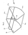
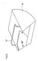
- the collecting device 16 is formed from a frame 17, which consists of rods 17a welded to one another, and the sheath 18 surrounding the frame 17.
- the casing 18 surrounds the frame 17 and leaves an opening in the direction of the housing 2 through which the chopped material can pass from the discharge opening 15 of the chopper 1 into the collecting device 16.
- the collecting device 16 corresponds approximately to a circular section.
- the surface of the casing 18 facing away from the filling opening 22 is provided with an opening 21 which can be closed by a flap 19.
- the cover 18 is formed from a film reinforced and air-impermeable film.
- the flap 19 can be connected to the stationary part of the sheath 18, in particular its edges surrounding the opening 21, via push buttons 20.
- the trained as push buttons 20 Ver closures can also be designed in the form of Velcro fasteners, zippers or the like.
- the frame 17 can be provided with hooks 26 which are provided for hooking onto corresponding hook bolts 27 which are assigned to the support frame 3 or the housing 2. The arrangement of these is described in more detail below in connection with the individual possibilities of articulation.
- the cutting unit 5 is arranged in the housing 2.
- the cutting unit 5 comprises the knife 6 mounted on the drive shaft 9.
- the drive shaft 9 is rotatably held in a bearing 8 in the housing 2.
- the cutting edges of the knife 6 work together with a counter holder 7 which is detachably fastened in the housing 2.
- the counter holder 7 can be removed to replace the knife 6.
- the housing 2 is provided with an opening which is closed by a cover 10.
- a motor 11 with its drive shaft can be connected directly to the drive shaft 9.
- the drive shaft 9 is provided with a pulley 12, over which a drive belt 14 leading to the pulley 13 of the motor 11 is placed.
- the motor 11 is mounted at a distance from the knife 6 and the drive shaft 9 on a bracket which is connected to the housing 2.
- the housing 2 Towards the front, the housing 2 has the ejection opening 15, which opens into the collecting device 16 when it is installed.
- hanging bolts 27 are assigned to the cover 10, via which the hanging hooks 26, which are attached to the upward-facing end of the frame 17, will grip.
- a through hole 28 is arranged in one of the two side walls of the housing 2.
- a pushbutton switch 31 is arranged in the interior of the housing 2 in the area of this through bore 28.
- a screw button 32 is assigned to the collecting device 16. This is captive in a threaded bore 36 in a holder as a designed screw bearing 33 on the frame 17. When the collecting device 16 is suspended, the threaded shaft 34 of the screw button 32 can pass through the bore 28. The end 35 of the threaded shaft 34 actuates the pushbutton switch 31 when a sufficient screw-in depth has been achieved. The circuit is closed so that the motor 11 can drive the knife 6 of the cutting mechanism 5.
- the assignment of the suspension bolts 27 to the cover 10 has also the advantage that it is only possible to mount the collecting device 16 and thus operate the chopper 1 when the bearing cover 10 is closed. This ensures that when a knife has been changed, start-up is only possible if the opening to the cutting unit 5 in the housing 2 is actually closed by the cover 10.
- the actuation of the pushbutton switch 31 is provided via an actuating lever 30 which is assigned to the handle 25.
- the key switch 31 is concealed in the housing 2 or in the support frame.
- the actuating lever 30 extends through an opening 28 in the housing 2.
- the key switch 31 is fastened with its key in the area of this opening 28.
- the actuating lever 30 is connected to the pivotable carrying handle 23. This is pivotably arranged on the frame 17 of the collecting device 16 via a pivot bearing 24. It is held in a depressed position by a locking spring 25. In this position, the actuating lever 30 passes through the opening 28 and is supported on the pushbutton switch 31, as a result of which the circuit is closed.
- the actuating lever 30 On the side, the actuating lever 30 has an inclined support surface 29 which bears on a bolt 37.
- the hooks 26 are arranged in this embodiment at the lower end of the frame 17 of the collecting device 16. They overlap suspension bolts 27 which are attached to the support frame 3.
- the collecting device 16 is cantilevered on one side. The force resulting from the chopped material located in the collecting device 16 generates a torque around the suspension bolts 27, which must be absorbed by the spring-loaded actuating lever 30 in connection with the support surfaces 29 supported on the bolt 40.
- the actuating lever 30 slides down with the support surface 29 on the bolt 37 and away from the system on the pushbutton switch 31.
- a catching device can be provided which ensures that only a small pivoting away from the ejection opening 15 can take place.
- the swing-out movement must be so large that a safe switch-off, i.e. safe interruption of the circuit is ensured by the pushbutton switch 31, but on the other hand, a passage by hand through the released space is not possible.
- the key switch 31 actuates an electromagnetic clutch.
- the clutch is switched on when the actuating lever 30 is in contact with the key switch 31, ie a torque is transmitted from the drive shaft 9 to the rotating knife 6.
- the clutch 38 is moved into the disengaged position, so that the torque flow from the drive shaft 9 to the knife 6 of the cutting mechanism 5 is interrupted.
- a brake is applied, which acts on the shaft associated with the knife 6 and stops the knife 6.
Landscapes
- Engineering & Computer Science (AREA)
- Food Science & Technology (AREA)
- Life Sciences & Earth Sciences (AREA)
- Biodiversity & Conservation Biology (AREA)
- Ecology (AREA)
- Forests & Forestry (AREA)
- Environmental Sciences (AREA)
- Crushing And Pulverization Processes (AREA)
Priority Applications (1)
| Application Number | Priority Date | Filing Date | Title |
|---|---|---|---|
| AT90115342T ATE95730T1 (de) | 1989-09-02 | 1990-08-10 | Haecksler mit auffangvorrichtung fuer das haeckselgut. |
Applications Claiming Priority (2)
| Application Number | Priority Date | Filing Date | Title |
|---|---|---|---|
| DE3929260 | 1989-09-02 | ||
| DE3929260A DE3929260C1 (fr) | 1989-09-02 | 1989-09-02 |
Publications (2)
| Publication Number | Publication Date |
|---|---|
| EP0416316A1 true EP0416316A1 (fr) | 1991-03-13 |
| EP0416316B1 EP0416316B1 (fr) | 1993-10-13 |
Family
ID=6388549
Family Applications (1)
| Application Number | Title | Priority Date | Filing Date |
|---|---|---|---|
| EP90115342A Revoked EP0416316B1 (fr) | 1989-09-02 | 1990-08-10 | Broyeur avec réceptacle pour les débris broyés |
Country Status (3)
| Country | Link |
|---|---|
| EP (1) | EP0416316B1 (fr) |
| AT (1) | ATE95730T1 (fr) |
| DE (1) | DE3929260C1 (fr) |
Cited By (3)
| Publication number | Priority date | Publication date | Assignee | Title |
|---|---|---|---|---|
| EP2335828A1 (fr) * | 2009-12-19 | 2011-06-22 | Viking GmbH | Broyeur de jardin |
| NL2018142B1 (en) * | 2017-01-07 | 2018-07-25 | Ecocreation B V | Composting apparatus |
| IT201700103530A1 (it) * | 2017-09-15 | 2019-03-15 | F B C Sas Di Frati Omar & C | Macchina per la frantumazione di materiali, in particolare per la triturazione di materiali residui di natura vegetale |
Families Citing this family (1)
| Publication number | Priority date | Publication date | Assignee | Title |
|---|---|---|---|---|
| DE502008003022D1 (de) | 2008-09-18 | 2011-05-12 | Viking Gmbh | Häcksler |
Citations (6)
| Publication number | Priority date | Publication date | Assignee | Title |
|---|---|---|---|---|
| US3553947A (en) * | 1968-08-12 | 1971-01-12 | Root Mfg Co Inc | Grass catcher for lawnmowers |
| FR2206900A1 (fr) * | 1972-11-18 | 1974-06-14 | Jute Spinnerei Weberei Bremen | |
| AU452098B2 (en) * | 1971-03-19 | 1974-08-29 | Scott Bonnar Limited | Grass catcher securing means |
| FR2350049A2 (fr) * | 1973-10-16 | 1977-12-02 | Bernard Moteurs | Perfectionnements aux tondeuses a gazon comportant un bac collecteur d'herbe |
| DE3325766A1 (de) * | 1983-07-16 | 1985-01-24 | Viking-Umwelttechnik GmbH, Kufstein | Vorrichtung zum zerkleinern von haeckselgut |
| DE8605558U1 (de) * | 1986-02-28 | 1986-06-05 | Wilhelm Pollmeier GmbH & Co, 59227 Ahlen | Gartenhäcksler mit Anlaufsicherung |
Family Cites Families (1)
| Publication number | Priority date | Publication date | Assignee | Title |
|---|---|---|---|---|
| DE3125834C2 (de) * | 1981-07-01 | 1984-02-16 | Gloria-Werke H. Schulte-Frankenfeld Gmbh & Co, 4724 Wadersloh | Häckseler |
-
1989
- 1989-09-02 DE DE3929260A patent/DE3929260C1/de not_active Expired - Lifetime
-
1990
- 1990-08-10 AT AT90115342T patent/ATE95730T1/de not_active IP Right Cessation
- 1990-08-10 EP EP90115342A patent/EP0416316B1/fr not_active Revoked
Patent Citations (6)
| Publication number | Priority date | Publication date | Assignee | Title |
|---|---|---|---|---|
| US3553947A (en) * | 1968-08-12 | 1971-01-12 | Root Mfg Co Inc | Grass catcher for lawnmowers |
| AU452098B2 (en) * | 1971-03-19 | 1974-08-29 | Scott Bonnar Limited | Grass catcher securing means |
| FR2206900A1 (fr) * | 1972-11-18 | 1974-06-14 | Jute Spinnerei Weberei Bremen | |
| FR2350049A2 (fr) * | 1973-10-16 | 1977-12-02 | Bernard Moteurs | Perfectionnements aux tondeuses a gazon comportant un bac collecteur d'herbe |
| DE3325766A1 (de) * | 1983-07-16 | 1985-01-24 | Viking-Umwelttechnik GmbH, Kufstein | Vorrichtung zum zerkleinern von haeckselgut |
| DE8605558U1 (de) * | 1986-02-28 | 1986-06-05 | Wilhelm Pollmeier GmbH & Co, 59227 Ahlen | Gartenhäcksler mit Anlaufsicherung |
Cited By (3)
| Publication number | Priority date | Publication date | Assignee | Title |
|---|---|---|---|---|
| EP2335828A1 (fr) * | 2009-12-19 | 2011-06-22 | Viking GmbH | Broyeur de jardin |
| NL2018142B1 (en) * | 2017-01-07 | 2018-07-25 | Ecocreation B V | Composting apparatus |
| IT201700103530A1 (it) * | 2017-09-15 | 2019-03-15 | F B C Sas Di Frati Omar & C | Macchina per la frantumazione di materiali, in particolare per la triturazione di materiali residui di natura vegetale |
Also Published As
| Publication number | Publication date |
|---|---|
| EP0416316B1 (fr) | 1993-10-13 |
| DE3929260C1 (fr) | 1991-02-14 |
| ATE95730T1 (de) | 1993-10-15 |
Similar Documents
| Publication | Publication Date | Title |
|---|---|---|
| DE3312991C2 (de) | Vorrichtung zum Zerkleinern von Materialien, wie Dokumenten etc. | |
| DE3312992C2 (de) | Gerät zum Zerkleinern von Materialien, wie Dokumenten etc., insbesondere Aktenvernichter | |
| DE2913435A1 (de) | Abschliessbares muellbehaeltersystem | |
| DE202010000032U1 (de) | Verriegelungsvorrichtung und Sicherungseinrichtung für einen Arbeitsbereich einer Maschine | |
| EP0551143A2 (fr) | Appareil hacheur découpeur | |
| DE4408471A1 (de) | Aktenvernichter mit Auffangbeutel für das zerkleinerte Material bzw. Schnittgut | |
| EP0416316B1 (fr) | Broyeur avec réceptacle pour les débris broyés | |
| EP0674983A1 (fr) | Dispositif de granulation pour matériau filiforme | |
| DE69412165T2 (de) | Papiervernichter, insbesondere für Wertpapiere | |
| EP1259326B1 (fr) | Couvercle d'une dechiqueteuse de documents destine a recevoir et guider des documents | |
| DE202015009627U1 (de) | Papier aus einer Aktenvernichtung | |
| DE19618478C1 (de) | Schriftgutvernichter | |
| DE1130683B (de) | Vorrichtung zum Zerkleinern von Papier, insbesondere Knuellpapier, Pappe u. dgl. | |
| EP0313832B1 (fr) | Métier à filer avec dispositif pour la maintenance des postes de filage ou de retordage | |
| DE3434177A1 (de) | Vorrichtung zum zerkleinern folienartiger informationstraeger | |
| DE19633520C2 (de) | Verschließbarer Abfallbehälter, insbesondere als Frontlade-Großbehälter | |
| DE8915638U1 (de) | Häcksler mit Auffangvorrichtung für das Häckselgut | |
| DE3325766A1 (de) | Vorrichtung zum zerkleinern von haeckselgut | |
| EP1354826B1 (fr) | Armoire à poubelle | |
| DE2942241A1 (de) | Vorrichtung zur begrenzung der fuellhoehe bei einem zu beschickenden behaelter | |
| DE102020129511A1 (de) | Vorrichtung zum Zerkleinern von Abfällen | |
| DE4406304C2 (de) | Häckseleinrichtung zur Zerkleinerung von Erntegut | |
| EP0979786B2 (fr) | Récipient à ordures | |
| DE4431173A1 (de) | Abfallzerkleinerungsvorrichtung | |
| DE9202922U1 (de) | Auszugsanordnung für eine Müllsackhalterung |
Legal Events
| Date | Code | Title | Description |
|---|---|---|---|
| PUAI | Public reference made under article 153(3) epc to a published international application that has entered the european phase |
Free format text: ORIGINAL CODE: 0009012 |
|
| AK | Designated contracting states |
Kind code of ref document: A1 Designated state(s): AT DE FR GB IT SE |
|
| 17P | Request for examination filed |
Effective date: 19910223 |
|
| 17Q | First examination report despatched |
Effective date: 19920413 |
|
| GRAA | (expected) grant |
Free format text: ORIGINAL CODE: 0009210 |
|
| AK | Designated contracting states |
Kind code of ref document: B1 Designated state(s): AT DE FR GB IT SE |
|
| REF | Corresponds to: |
Ref document number: 95730 Country of ref document: AT Date of ref document: 19931015 Kind code of ref document: T |
|
| RBV | Designated contracting states (corrected) |
Designated state(s): AT FR GB IT SE |
|
| GBT | Gb: translation of ep patent filed (gb section 77(6)(a)/1977) |
Effective date: 19931021 |
|
| ITF | It: translation for a ep patent filed | ||
| ET | Fr: translation filed | ||
| PLBI | Opposition filed |
Free format text: ORIGINAL CODE: 0009260 |
|
| PGFP | Annual fee paid to national office [announced via postgrant information from national office to epo] |
Ref country code: GB Payment date: 19940720 Year of fee payment: 5 |
|
| PGFP | Annual fee paid to national office [announced via postgrant information from national office to epo] |
Ref country code: FR Payment date: 19940817 Year of fee payment: 5 |
|
| PGFP | Annual fee paid to national office [announced via postgrant information from national office to epo] |
Ref country code: AT Payment date: 19940823 Year of fee payment: 5 |
|
| 26 | Opposition filed |
Opponent name: BRILL PRODUKTIONS GMBH Effective date: 19940705 |
|
| PGFP | Annual fee paid to national office [announced via postgrant information from national office to epo] |
Ref country code: SE Payment date: 19940824 Year of fee payment: 5 |
|
| EUG | Se: european patent has lapsed |
Ref document number: 90115342.9 Effective date: 19950329 |
|
| RDAG | Patent revoked |
Free format text: ORIGINAL CODE: 0009271 |
|
| STAA | Information on the status of an ep patent application or granted ep patent |
Free format text: STATUS: PATENT REVOKED |
|
| 27W | Patent revoked |
Effective date: 19941119 |
|
| GBPR | Gb: patent revoked under art. 102 of the ep convention designating the uk as contracting state |
Free format text: 941119 |