EP0415293A2 - Vorrichtung zur Speicherung von Reissverschlussschiebern - Google Patents
Vorrichtung zur Speicherung von Reissverschlussschiebern Download PDFInfo
- Publication number
- EP0415293A2 EP0415293A2 EP90116296A EP90116296A EP0415293A2 EP 0415293 A2 EP0415293 A2 EP 0415293A2 EP 90116296 A EP90116296 A EP 90116296A EP 90116296 A EP90116296 A EP 90116296A EP 0415293 A2 EP0415293 A2 EP 0415293A2
- Authority
- EP
- European Patent Office
- Prior art keywords
- slider
- stocker
- sliders
- chute
- stockers
- Prior art date
- Legal status (The legal status is an assumption and is not a legal conclusion. Google has not performed a legal analysis and makes no representation as to the accuracy of the status listed.)
- Granted
Links
Images


Classifications
-
- B—PERFORMING OPERATIONS; TRANSPORTING
- B65—CONVEYING; PACKING; STORING; HANDLING THIN OR FILAMENTARY MATERIAL
- B65G—TRANSPORT OR STORAGE DEVICES, e.g. CONVEYORS FOR LOADING OR TIPPING, SHOP CONVEYOR SYSTEMS OR PNEUMATIC TUBE CONVEYORS
- B65G1/00—Storing articles, individually or in orderly arrangement, in warehouses or magazines
-
- A—HUMAN NECESSITIES
- A44—HABERDASHERY; JEWELLERY
- A44B—BUTTONS, PINS, BUCKLES, SLIDE FASTENERS, OR THE LIKE
- A44B19/00—Slide fasteners
- A44B19/42—Making by processes not fully provided for in one other class, e.g. B21D53/50, B21F45/18, B22D17/16, B29D5/00
- A44B19/62—Assembling sliders in position on stringer tapes
-
- B—PERFORMING OPERATIONS; TRANSPORTING
- B65—CONVEYING; PACKING; STORING; HANDLING THIN OR FILAMENTARY MATERIAL
- B65G—TRANSPORT OR STORAGE DEVICES, e.g. CONVEYORS FOR LOADING OR TIPPING, SHOP CONVEYOR SYSTEMS OR PNEUMATIC TUBE CONVEYORS
- B65G47/00—Article or material-handling devices associated with conveyors; Methods employing such devices
- B65G47/22—Devices influencing the relative position or the attitude of articles during transit by conveyors
- B65G47/26—Devices influencing the relative position or the attitude of articles during transit by conveyors arranging the articles, e.g. varying spacing between individual articles
Definitions
- This invention relates to an apparatus for storing arrays of sliders preparatory to application onto a fastener stringer chain in the production of slide fasteners.
- An apparatus of this character is disclosed for example in British Patent 1,309,014 wherein there is provided a store in the form of a rectangular plate having separate tracks for storing rows of sliders of different types or colors, a selected row of sliders being transferred to the position of a slider holder and the desired slider picked up and drawn onto a slide fastener chain.
- Sliders are mounted and stored on the storing plate by hand or by means of a vibratory feeder while it is attached to a slider feed device because the plate is not removable and in addition, as many vibratory feeders are required as are the number of different types of sliders that are to be stored. This operation is time-consuming and tedious.
- the present invention seeks to provide an apparatus for storing a plurality of arrays of sliders for slide fastener in such a manner that there can be maintained a sufficient inventory of sliders of different types and colors automatically without need for separate vibratory feeders and that any selected array of sliders can be readily fed into position for application onto a fastener stringer chain.
- an apparatus for storing arrays of sliders to be applied onto a fastener stringer chain which comprises: a stocker holder having a plurality of a first group of hooks and a second group of hooks; a plurality of slider stockers removably mounted on the hooks and each having a rail; a slider supply means including a chute for lining up and transferring a supply of sliders from the supply means onto the slider stockers; and a drive means for moving the stocker holder relatively to the slider supply means to bring the slider stockers successively into operative position registering with the chute, the first and second groups of hooks being displaced with respect to their common horizontal axis such that each of the slider stockers is tilted downwardly to allow gravity movement of the sliders along the rail.
- the slider feeding unit 100 essentially comprises a pair of oppositely disposed stocker holders 101, only one of which is shown, and a plurality of slider stockers 102 removably secured at opposite ends to the stock holders 101 and each adapted to releasably hold thereon an array of sliders S.
- a slider transfer holder 103 is reciprocably movable transversely across the arrays of slider stockers 102 by means of a timing drive 104 to pick up a desired one of sliders S for delivery to a slide guide 105, from where the slider S is transferred to the slider applying unit 200 having a slider holder 201 rotatable into and out of the path of the stringer chain C.
- the slider S is threaded through and mounted over rows of coupling elements E of the stringer chain C in a manner well known in the art.
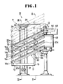
- an apparatus generally designated 10 in Figure 1 embodying the invention is provided to replenish sliders S at the slider feeding unit 100 by exchanging an empty slider stocker with a filled up slider stocker.
- the apparatus 10 shown in Figure 1 comprises a slider stocker unit 11 and a slider supply unit 12.
- the slider stocker unit 11 includes a stocker holder 13 in the form of a rectangular frame having a pair of first and second vertical frame members 14 and 15 and a pair of first and second horizontal frame members 16 and 17 transversely extending between and respectively connected to upper and lower ends of the vertical frame members 14 and 15.
- a plurality of equally spaced stocker hooks 18a - 18d project horizontally from the first vertical frame member 14 for releasably retaining slider stockers 20a - 20d at one or lower ends thereof.
- the second vertical frame member 15 has a plurality of similar stocker hooks 19a - 19d for releasably retaining the slider stockers 20a - 20d at upper intermediate positions remote from the lower ends thereof.
- One group of hooks 18a - 18d and the other corresponding group of hooks 19a - 19d are displaced with respect to their common horizontal axis such that the slider stockers 20a - 20d when mounted in place on the stocker holder 13 are tilted downwardly toward the first vertical frame member 14 as shown in Figure 1.
- Each of the slider stockers 20 (20a - 20d) generally in the form of a chute has a rail 21 along which the sliders S slide down by own gravity. More specifically, the slider S has an upper wing S1 and a lower wing S2 defining therebetween a guide channel S3 terminating at a neck S4.
- the slider S is mounted with its upper and lower wings S1, S2 astride the rail 21 of the slider stocker 20 as better shown in Figures 6, 7 and 10.
- the slider stocker 20 has a longitudinal inverted L-shaped cover 22 overlying the rail 21 and adapted to prevent the sliders S from falling out or derailing.
- Each of the hooks 18a - 18d, (19a - 19d) has a base portion 23 secured to the stocker holder 13 and a pair of spaced first and second lugs 24 and 25 interconnected by a pin 26 and accommodating therebetween a spring 27 adapted to urge the slider stocker 20 in place between the first lug 24 and the base portion 23 as better shown in Figure 5.
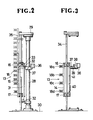
- a support post 28 extends vertically between and is reared to upper and lower machine frames 29 and 30.
- a first pneumatically operated cylinder 31 is vertically disposed and secured by brackets 32 to the support post 28 as shown in Figures 1 and 2.
- a piston rod 33 of the first cylinder 31 has its operating end connected to the upper horizontal frame member 16 of the stocker holder 13 so that its upward stroke causes the stocker holder 13 to move upwardly along a pair of spaced vertical guide rods 34, 35 extending between the upper and lower machine frames 29 and 30 thereby to bring the slider stockers (20a - 20d) successively into operative position registering or interconnecting with a slider chute 48 later described.
- a second pneumatic cylinder 36 is secured by a bracket 37 to the support post 28 and has its piston rod 38 connected to a positioning pin 39 extending horizontally from the bracket 37.
- a retainer plate 40 extends vertically between and is secured to the upper (first) and lower (second) frames 16 and 17 of the stocker holder 13. As better shown in Figure 3, the retainer plate 40 has a plurality of retaining grooves 41 corresponding in position to the hooks 18a - 18d on the first vertical frame 14 of the stocker holder 13. The retaining grooves 41 each are receptive of the positioning pin 39 so that any one of the slider stockers 20a - 20d, when brought into position for receiving sliders S from the slider supply unit 12 as later described, is firmly retained in place against movement.
- a third pneumatic cylinder 42 is secured to a support block 43 located adjacent to an inlet end 44 of the uppermost slider stocker 20a held in operative position and has its piston rod 45 horizontally movable toward and away from the cover 22 of the slider stocker 20a.
- a guide plate 46 is secured to a support block 47 and spaced from the support block 43 by a distance to clear the slider stocker 20 as shown in Figure 4.
- the slider supply unit 12 comprises a parts feeder 49 of conventional construction with a bowl 50 containing a multiplicity of sliders S of different types or colors and with the slider chute 48 extending from the bowl 50. Sliders S are lined up by vibratory action of the bowl 50 and progressively forwarded along the chute 48 in a manner well known in the art.
- the chute 48 has a downwardly slanted slide surface 48a at its free end as shown in Figure 6, gravity movement of the slider 20 being accelerated along the slanted surface 48a to facilitate its transfer onto the slider stocker 20.
- the apparatus 10 With the apparatus 10 thus constructed according to the first embodiment of the invention, its operation for the sake of brevity begins with actuation of the first cylinder 31 whereby the uppermost slider stocker 20a is brought up into operative position with its inlet end 44 held in confrontation with the free end of the slider chute 48 at the supply unit 12. This is followed by actuation of the second cylinder 36 so that its piston rod 38 is receptively engaged in the retaining groove 41 of the retainer plate 40 thereby to retain the uppermost slider stocker 20a stably in place.
- the third cylinder 42 then operates so as to bring the cover 22 of the slider stocker 20a into abutting engagement with the guide plate 46 thereby to hold the rail 21 of the slider stocker 20a in alignment with the slanted slide surface 48a of the slider chute 48, when the sliders S are allowed to move onto and then progressively along the rail 21 until they fill up the uppermost slider stocker 20a.
- the interrelated operation of the three cylinders 31, 36 and 42 may be conveniently governed by a suitable automatic control means not shown.
- Figure 8 shows a modification of the apparatus 10 in which the slider stocker unit 11 is held stationary while the slider supply unit 12 is made movable relative thereto by means of a pneumatically operated cylinder 60.
- Figure 9 shows another modification in which the slider stockers 20 are mounted in horizontal parallel relation to one another and moved horizontally successively into slider filling position with respect to the slider supply unit 12.
- the slider supply unit 12 may be movable relative to the slider stockers 20.
Landscapes
- Engineering & Computer Science (AREA)
- Mechanical Engineering (AREA)
- Slide Fasteners (AREA)
- Chutes (AREA)
- Warehouses Or Storage Devices (AREA)
- Feeding Of Articles To Conveyors (AREA)
Applications Claiming Priority (2)
| Application Number | Priority Date | Filing Date | Title |
|---|---|---|---|
| JP1219748A JPH0643204B2 (ja) | 1989-08-26 | 1989-08-26 | スライダー補給装置 |
| JP219748/89 | 1989-08-26 |
Publications (3)
| Publication Number | Publication Date |
|---|---|
| EP0415293A2 true EP0415293A2 (de) | 1991-03-06 |
| EP0415293A3 EP0415293A3 (en) | 1991-04-17 |
| EP0415293B1 EP0415293B1 (de) | 1993-11-03 |
Family
ID=16740377
Family Applications (1)
| Application Number | Title | Priority Date | Filing Date |
|---|---|---|---|
| EP90116296A Expired - Lifetime EP0415293B1 (de) | 1989-08-26 | 1990-08-24 | Vorrichtung zur Speicherung von Reissverschlussschiebern |
Country Status (13)
| Country | Link |
|---|---|
| US (1) | US5114305A (de) |
| EP (1) | EP0415293B1 (de) |
| JP (1) | JPH0643204B2 (de) |
| KR (1) | KR930005956B1 (de) |
| AU (1) | AU623033B2 (de) |
| BR (1) | BR9004292A (de) |
| CA (1) | CA2023959C (de) |
| DE (1) | DE69004384T2 (de) |
| ES (1) | ES2045692T3 (de) |
| FI (1) | FI96092C (de) |
| HK (1) | HK75997A (de) |
| MY (1) | MY106462A (de) |
| ZA (1) | ZA906756B (de) |
Families Citing this family (7)
| Publication number | Priority date | Publication date | Assignee | Title |
|---|---|---|---|---|
| CN101157411B (zh) * | 2007-11-26 | 2010-08-04 | 王建生 | 滑槽式仓储装置 |
| CN102275747B (zh) * | 2011-05-10 | 2012-12-12 | 江苏迅捷装具科技有限公司 | 一种槽式储物补仓装置 |
| CN103318634B (zh) * | 2013-06-19 | 2016-05-04 | 永高股份有限公司 | 球阀阀芯的提升式自动理料输送机构 |
| CN104837749B (zh) * | 2014-02-18 | 2017-05-31 | Ykk株式会社 | 拉链拉头供给装置 |
| KR101652638B1 (ko) * | 2015-05-27 | 2016-08-30 | 강릉원주대학교산학협력단 | 고추냉이를 함유하는 음료 및 그 제조방법 |
| CN109160304B (zh) * | 2018-07-14 | 2020-02-18 | 广东豫兆临药业连锁股份有限公司 | 一种物流仓储用可调节式中转货架 |
| CN114348611A (zh) * | 2021-12-30 | 2022-04-15 | 大连奥托股份有限公司 | 一种角度可调的重力滑移缓存料台 |
Family Cites Families (18)
| Publication number | Priority date | Publication date | Assignee | Title |
|---|---|---|---|---|
| US1210860A (en) * | 1915-12-04 | 1917-01-02 | Edgar A Sims | Apparatus for cooking canned goods. |
| US2053544A (en) * | 1930-06-28 | 1936-09-08 | Winterhalter Martin | Method of and apparatus for supplying sliding clasp fastener elements to stringers |
| US2017814A (en) * | 1933-02-04 | 1935-10-15 | Henkels Hugo | Device for the manufacture of sliding clasp fastenings |
| US3018020A (en) * | 1958-12-19 | 1962-01-23 | Western Electric Co | Article storage and dispensing apparatus |
| US3526743A (en) * | 1967-05-26 | 1970-09-01 | Trw Inc | Apparatus for dispensing studs to plural welding tools |
| DE1913873C3 (de) * | 1969-03-19 | 1974-06-06 | William Prym-Werke Kg, 5190 Stolberg | Vorrichtung zum Aufziehen von Reißverschlußschiebern auf Gliederreihen von Reißverschlüssen |
| JPS5090438A (de) * | 1973-12-11 | 1975-07-19 | ||
| US4173283A (en) * | 1973-12-24 | 1979-11-06 | Yoshida Kogyo Kabushiki Kaisha | Support strip for ready-for use arrangement of sliders in the manufacture of slide fasteners |
| JPS597780B2 (ja) * | 1976-07-20 | 1984-02-21 | 株式会社東芝 | 軟質磁性材料 |
| JPS5934325Y2 (ja) * | 1979-09-07 | 1984-09-22 | ワイケイケイ株式会社 | スライドフアスナ−のスライダ−供給装置 |
| JPS5951822B2 (ja) * | 1981-12-28 | 1984-12-15 | ワイケイケイ株式会社 | 未切断ファスナ−チェ−ンにスライダ−を装着するため、スライダ−をスライダ−ポケットに供給する方法および装置 |
| JPS59117150U (ja) * | 1983-01-26 | 1984-08-07 | 株式会社アドバンテスト | Ic試験装置のic滑走レ−ル |
| KR850001911B1 (ko) * | 1984-09-28 | 1985-12-31 | 재단법인 한국기계연구소 | 파스너(Fastener)용 슬라이더의 연속 조립장치 |
| JPS62161621A (ja) * | 1985-08-02 | 1987-07-17 | Hitachi Electronics Eng Co Ltd | Icマガジン供給機構 |
| DE3539965A1 (de) * | 1985-11-11 | 1987-05-14 | Ueberreiter Ekkehard | Vorrichtung zum pruefen und sortieren von elektronischen bauelementen |
| JPH0420820Y2 (de) * | 1986-01-22 | 1992-05-13 | ||
| JPH0655172B2 (ja) * | 1986-07-03 | 1994-07-27 | 吉田工業株式会社 | スライドフアスナ−用スライダ−の供給装置 |
| JPH0620413Y2 (ja) * | 1986-08-15 | 1994-06-01 | 吉田工業株式会社 | スライドフアスナ−用スライダ−移送装置 |
-
1989
- 1989-08-26 JP JP1219748A patent/JPH0643204B2/ja not_active Expired - Fee Related
-
1990
- 1990-08-13 AU AU60926/90A patent/AU623033B2/en not_active Ceased
- 1990-08-20 FI FI904119A patent/FI96092C/fi not_active IP Right Cessation
- 1990-08-24 DE DE69004384T patent/DE69004384T2/de not_active Expired - Lifetime
- 1990-08-24 ZA ZA906756A patent/ZA906756B/xx unknown
- 1990-08-24 CA CA002023959A patent/CA2023959C/en not_active Expired - Lifetime
- 1990-08-24 EP EP90116296A patent/EP0415293B1/de not_active Expired - Lifetime
- 1990-08-24 ES ES90116296T patent/ES2045692T3/es not_active Expired - Lifetime
- 1990-08-24 MY MYPI90001437A patent/MY106462A/en unknown
- 1990-08-24 BR BR909004292A patent/BR9004292A/pt not_active IP Right Cessation
- 1990-08-24 US US07/571,717 patent/US5114305A/en not_active Expired - Fee Related
- 1990-08-25 KR KR1019900013186A patent/KR930005956B1/ko not_active Expired - Fee Related
-
1997
- 1997-06-05 HK HK75997A patent/HK75997A/en not_active IP Right Cessation
Also Published As
| Publication number | Publication date |
|---|---|
| JPH0383703A (ja) | 1991-04-09 |
| AU6092690A (en) | 1991-08-01 |
| CA2023959A1 (en) | 1991-02-27 |
| US5114305A (en) | 1992-05-19 |
| FI96092B (fi) | 1996-01-31 |
| ZA906756B (en) | 1991-06-26 |
| DE69004384T2 (de) | 1994-05-19 |
| JPH0643204B2 (ja) | 1994-06-08 |
| FI904119A0 (fi) | 1990-08-20 |
| AU623033B2 (en) | 1992-04-30 |
| EP0415293B1 (de) | 1993-11-03 |
| FI96092C (fi) | 1996-05-10 |
| MY106462A (en) | 1995-05-30 |
| ES2045692T3 (es) | 1994-01-16 |
| KR910004444A (ko) | 1991-03-28 |
| EP0415293A3 (en) | 1991-04-17 |
| BR9004292A (pt) | 1991-09-03 |
| DE69004384D1 (de) | 1993-12-09 |
| HK75997A (en) | 1997-06-13 |
| CA2023959C (en) | 1994-05-31 |
| KR930005956B1 (ko) | 1993-06-30 |
Similar Documents
| Publication | Publication Date | Title |
|---|---|---|
| US5427492A (en) | Method for shifting goods and apparatus therefor | |
| EP0415293B1 (de) | Vorrichtung zur Speicherung von Reissverschlussschiebern | |
| EP0594079B1 (de) | Verfahren und Vorrichtung zum Transport von Tragplatten | |
| US4763811A (en) | Parts feeder | |
| US5079829A (en) | Automatic assembly apparatus | |
| EP0409068B1 (de) | Vorrichtung zur Herstellung eines Reissverschlusses | |
| KR880001802B1 (ko) | 회로판에의 전자부품 부착장치 | |
| US4333586A (en) | Insertion machine for integrated circuits | |
| US4374559A (en) | Apparatus for handling articles | |
| US4829748A (en) | Apparatus for arraying parts on respective trays | |
| US2500376A (en) | Nut feed for castellating machines | |
| GB2256160A (en) | Apparatus for installing clamps. | |
| EP0968924A1 (de) | Verfahren und Vorrichtung zum Anbringen eines blattförmigen Gegenstandes um den Hals von Flaschen in einem Kasten | |
| CN212884818U (zh) | 一种座椅托盘传送机构及座椅托盘销钉铆接机 | |
| US5746482A (en) | Brush body feeding device | |
| US5217120A (en) | Apparatus for loading and unloading sleeves for integrated circuit ester | |
| JP3812208B2 (ja) | ボルト供給装置 | |
| JPH0777923B2 (ja) | 物品搬送方法および装置 | |
| JPH03500406A (ja) | 連続した処理作業箇所に沿って物品搬送具を搬送する装置 | |
| JPH0357402A (ja) | スライドフアスナーのスライダー取付機におけるスライダー供給装置 | |
| US3159961A (en) | Bobbin magazine | |
| JPS61127402A (ja) | Ic詰め替え装置 | |
| CN117246670A (zh) | 一种自动化药房上药系统及方法 | |
| JPS623719A (ja) | エノキ茸栽培容器の自動搬入装置 | |
| JPH0717667A (ja) | 給糸体の交換装置 |
Legal Events
| Date | Code | Title | Description |
|---|---|---|---|
| PUAI | Public reference made under article 153(3) epc to a published international application that has entered the european phase |
Free format text: ORIGINAL CODE: 0009012 |
|
| PUAL | Search report despatched |
Free format text: ORIGINAL CODE: 0009013 |
|
| AK | Designated contracting states |
Kind code of ref document: A2 Designated state(s): BE CH DE ES FR GB IT LI NL SE |
|
| AK | Designated contracting states |
Kind code of ref document: A3 Designated state(s): BE CH DE ES FR GB IT LI NL SE |
|
| 17P | Request for examination filed |
Effective date: 19910724 |
|
| 17Q | First examination report despatched |
Effective date: 19921130 |
|
| GRAA | (expected) grant |
Free format text: ORIGINAL CODE: 0009210 |
|
| AK | Designated contracting states |
Kind code of ref document: B1 Designated state(s): BE CH DE ES FR GB IT LI NL SE |
|
| ITF | It: translation for a ep patent filed | ||
| REF | Corresponds to: |
Ref document number: 69004384 Country of ref document: DE Date of ref document: 19931209 |
|
| ET | Fr: translation filed | ||
| PLBE | No opposition filed within time limit |
Free format text: ORIGINAL CODE: 0009261 |
|
| STAA | Information on the status of an ep patent application or granted ep patent |
Free format text: STATUS: NO OPPOSITION FILED WITHIN TIME LIMIT |
|
| 26N | No opposition filed | ||
| REG | Reference to a national code |
Ref country code: CH Ref legal event code: PFA Free format text: YKK CORPORATION |
|
| ITPR | It: changes in ownership of a european patent |
Owner name: CAMBIO RAGIONE SOCIALE;YKK CORPORATION |
|
| REG | Reference to a national code |
Ref country code: FR Ref legal event code: CD |
|
| EAL | Se: european patent in force in sweden |
Ref document number: 90116296.6 |
|
| REG | Reference to a national code |
Ref country code: ES Ref legal event code: PC2A Owner name: YKK CORPORATION |
|
| NLT1 | Nl: modifications of names registered in virtue of documents presented to the patent office pursuant to art. 16 a, paragraph 1 |
Owner name: YKK CORPORATION TE TOKIO, JAPAN. |
|
| PGFP | Annual fee paid to national office [announced via postgrant information from national office to epo] |
Ref country code: ES Payment date: 19960802 Year of fee payment: 7 |
|
| PGFP | Annual fee paid to national office [announced via postgrant information from national office to epo] |
Ref country code: CH Payment date: 19960812 Year of fee payment: 7 |
|
| PGFP | Annual fee paid to national office [announced via postgrant information from national office to epo] |
Ref country code: GB Payment date: 19960815 Year of fee payment: 7 |
|
| PGFP | Annual fee paid to national office [announced via postgrant information from national office to epo] |
Ref country code: SE Payment date: 19970512 Year of fee payment: 8 |
|
| PGFP | Annual fee paid to national office [announced via postgrant information from national office to epo] |
Ref country code: BE Payment date: 19970529 Year of fee payment: 8 |
|
| PG25 | Lapsed in a contracting state [announced via postgrant information from national office to epo] |
Ref country code: GB Free format text: LAPSE BECAUSE OF NON-PAYMENT OF DUE FEES Effective date: 19970824 |
|
| PG25 | Lapsed in a contracting state [announced via postgrant information from national office to epo] |
Ref country code: ES Free format text: LAPSE BECAUSE OF THE APPLICANT RENOUNCES Effective date: 19970825 |
|
| PG25 | Lapsed in a contracting state [announced via postgrant information from national office to epo] |
Ref country code: LI Free format text: LAPSE BECAUSE OF NON-PAYMENT OF DUE FEES Effective date: 19970831 Ref country code: CH Free format text: LAPSE BECAUSE OF NON-PAYMENT OF DUE FEES Effective date: 19970831 |
|
| GBPC | Gb: european patent ceased through non-payment of renewal fee |
Effective date: 19970824 |
|
| REG | Reference to a national code |
Ref country code: CH Ref legal event code: PL |
|
| PG25 | Lapsed in a contracting state [announced via postgrant information from national office to epo] |
Ref country code: SE Free format text: LAPSE BECAUSE OF NON-PAYMENT OF DUE FEES Effective date: 19980825 |
|
| PG25 | Lapsed in a contracting state [announced via postgrant information from national office to epo] |
Ref country code: BE Free format text: LAPSE BECAUSE OF NON-PAYMENT OF DUE FEES Effective date: 19980831 |
|
| BERE | Be: lapsed |
Owner name: YKK CORP. Effective date: 19980831 |
|
| EUG | Se: european patent has lapsed |
Ref document number: 90116296.6 |
|
| REG | Reference to a national code |
Ref country code: ES Ref legal event code: FD2A Effective date: 20001009 |
|
| PGFP | Annual fee paid to national office [announced via postgrant information from national office to epo] |
Ref country code: FR Payment date: 20050809 Year of fee payment: 16 |
|
| PGFP | Annual fee paid to national office [announced via postgrant information from national office to epo] |
Ref country code: NL Payment date: 20050815 Year of fee payment: 16 |
|
| PGFP | Annual fee paid to national office [announced via postgrant information from national office to epo] |
Ref country code: IT Payment date: 20060831 Year of fee payment: 17 |
|
| PG25 | Lapsed in a contracting state [announced via postgrant information from national office to epo] |
Ref country code: NL Free format text: LAPSE BECAUSE OF NON-PAYMENT OF DUE FEES Effective date: 20070301 |
|
| NLV4 | Nl: lapsed or anulled due to non-payment of the annual fee |
Effective date: 20070301 |
|
| REG | Reference to a national code |
Ref country code: FR Ref legal event code: ST Effective date: 20070430 |
|
| PG25 | Lapsed in a contracting state [announced via postgrant information from national office to epo] |
Ref country code: FR Free format text: LAPSE BECAUSE OF NON-PAYMENT OF DUE FEES Effective date: 20060831 |
|
| PG25 | Lapsed in a contracting state [announced via postgrant information from national office to epo] |
Ref country code: IT Free format text: LAPSE BECAUSE OF NON-PAYMENT OF DUE FEES Effective date: 20070824 |
|
| PGFP | Annual fee paid to national office [announced via postgrant information from national office to epo] |
Ref country code: DE Payment date: 20090821 Year of fee payment: 20 |
|
| PG25 | Lapsed in a contracting state [announced via postgrant information from national office to epo] |
Ref country code: DE Free format text: LAPSE BECAUSE OF EXPIRATION OF PROTECTION Effective date: 20100824 |