EP0414873B1 - Scheibenreinigungsanlage, insbesondere für kraftfahrzeuge - Google Patents
Scheibenreinigungsanlage, insbesondere für kraftfahrzeuge Download PDFInfo
- Publication number
- EP0414873B1 EP0414873B1 EP19900904304 EP90904304A EP0414873B1 EP 0414873 B1 EP0414873 B1 EP 0414873B1 EP 19900904304 EP19900904304 EP 19900904304 EP 90904304 A EP90904304 A EP 90904304A EP 0414873 B1 EP0414873 B1 EP 0414873B1
- Authority
- EP
- European Patent Office
- Prior art keywords
- connecting piece
- cleaning system
- windshield cleaning
- washing liquid
- piece
- Prior art date
- Legal status (The legal status is an assumption and is not a legal conclusion. Google has not performed a legal analysis and makes no representation as to the accuracy of the status listed.)
- Expired - Lifetime
Links
- 238000004140 cleaning Methods 0.000 title claims abstract description 48
- 238000005406 washing Methods 0.000 claims abstract description 76
- 239000007788 liquid Substances 0.000 claims description 71
- 238000007789 sealing Methods 0.000 claims description 30
- 230000000149 penetrating effect Effects 0.000 claims 1
- 239000012530 fluid Substances 0.000 abstract description 5
- 238000009434 installation Methods 0.000 abstract 1
- 238000011161 development Methods 0.000 description 5
- 230000018109 developmental process Effects 0.000 description 5
- 230000005540 biological transmission Effects 0.000 description 4
- 239000004519 grease Substances 0.000 description 4
- 238000010276 construction Methods 0.000 description 3
- XLYOFNOQVPJJNP-UHFFFAOYSA-N water Substances O XLYOFNOQVPJJNP-UHFFFAOYSA-N 0.000 description 3
- 230000001771 impaired effect Effects 0.000 description 2
- 230000010354 integration Effects 0.000 description 2
- 235000010678 Paulownia tomentosa Nutrition 0.000 description 1
- 240000002834 Paulownia tomentosa Species 0.000 description 1
- 230000001419 dependent effect Effects 0.000 description 1
- 230000000694 effects Effects 0.000 description 1
- 238000007373 indentation Methods 0.000 description 1
- 230000003993 interaction Effects 0.000 description 1
- 238000004519 manufacturing process Methods 0.000 description 1
- 239000000463 material Substances 0.000 description 1
- 231100000989 no adverse effect Toxicity 0.000 description 1
- 230000002028 premature Effects 0.000 description 1
- 238000003825 pressing Methods 0.000 description 1
- 238000003892 spreading Methods 0.000 description 1
- 238000003860 storage Methods 0.000 description 1
- 239000000725 suspension Substances 0.000 description 1
- 210000002105 tongue Anatomy 0.000 description 1
Images




Classifications
-
- B—PERFORMING OPERATIONS; TRANSPORTING
- B60—VEHICLES IN GENERAL
- B60S—SERVICING, CLEANING, REPAIRING, SUPPORTING, LIFTING, OR MANOEUVRING OF VEHICLES, NOT OTHERWISE PROVIDED FOR
- B60S1/00—Cleaning of vehicles
- B60S1/02—Cleaning windscreens, windows or optical devices
- B60S1/46—Cleaning windscreens, windows or optical devices using liquid; Windscreen washers
- B60S1/48—Liquid supply therefor
- B60S1/52—Arrangement of nozzles; Liquid spreading means
- B60S1/522—Arrangement of nozzles; Liquid spreading means moving liquid spreading means, e.g. arranged in wiper arms
-
- B—PERFORMING OPERATIONS; TRANSPORTING
- B60—VEHICLES IN GENERAL
- B60S—SERVICING, CLEANING, REPAIRING, SUPPORTING, LIFTING, OR MANOEUVRING OF VEHICLES, NOT OTHERWISE PROVIDED FOR
- B60S1/00—Cleaning of vehicles
- B60S1/02—Cleaning windscreens, windows or optical devices
- B60S1/04—Wipers or the like, e.g. scrapers
- B60S1/32—Wipers or the like, e.g. scrapers characterised by constructional features of wiper blade arms or blades
- B60S1/34—Wiper arms; Mountings therefor
- B60S1/3415—Wiper arms; Mountings therefor with means for supplying cleaning fluid to windscreen cleaners, e.g. washers
-
- Y—GENERAL TAGGING OF NEW TECHNOLOGICAL DEVELOPMENTS; GENERAL TAGGING OF CROSS-SECTIONAL TECHNOLOGIES SPANNING OVER SEVERAL SECTIONS OF THE IPC; TECHNICAL SUBJECTS COVERED BY FORMER USPC CROSS-REFERENCE ART COLLECTIONS [XRACs] AND DIGESTS
- Y10—TECHNICAL SUBJECTS COVERED BY FORMER USPC
- Y10T—TECHNICAL SUBJECTS COVERED BY FORMER US CLASSIFICATION
- Y10T137/00—Fluid handling
- Y10T137/8593—Systems
- Y10T137/86268—With running joint between movable parts of system
Definitions
- the invention relates to a window cleaning system, in particular for motor vehicles, according to the features of the preamble of claim 1.
- the washing liquid is conveyed to nozzles which are arranged on the wiper lever and oscillate with it.
- the sweetening liquid is conveyed through a line within a bore in a wiper shaft, the end piece of the washing liquid line at the drive-side end of the wiper shaft being axially immersed in a cup-shaped connecting piece, from which a hose connector projects radially for connecting a washing liquid supply hose.
- the washer fluid line swings like the wiper shaft, while the connection piece is fixed in a rotationally fixed manner, because otherwise the washer fluid supply hose would be considerably stressed during operation of the wiper system and the risk of tearing off after a long period of operation could not be excluded.
- the connector is fixed to the frame via a radially projecting cantilever arm.
- the cantilever arm is not only used to prevent rotation, but the connection piece is also rigidly fixed to a stationary part.
- the present invention is therefore based on the object of developing such a window cleaning system with the simplest means so that the function, in particular a perfect seal and play-free storage, is ensured even after a longer operating time.
- the invention is based on the consideration that with a tension-free centering of the connection piece relative to the end piece of the washing liquid line, the eccentric movement or imbalance of the wiper shaft, which cannot be ruled out in the course of the operating time, has no adverse effect on the seal between the connection piece and the end piece, because the connection piece can participate in this movement caused by an imbalance.
- a flexible suspension of the connecting piece is thus provided according to the invention.
- the connector is held in a plane transverse to the axial direction of the shaft only by the end piece, and only a fuse is required in addition to the fixed part, which is only to prevent rotation of the connector. With such a design, no radial forces act on the bearing point, so that premature wear is not to be feared.
- connection piece is freely movable to a certain extent radially in each direction. If, for example, the anti-rotation device includes a fork-like extension protruding from the connecting piece and a stationary holding element engaging between its tines, it should be possible to pivot this fork-like extension to a certain extent around the holding element. This can be achieved very simply by forming this holding element as a round bar.
- the spring element required for this is fixed to the stationary element, which is necessary anyway as part of the anti-rotation device. Due to the multiple use of a part, manufacturing and assembly costs can be kept low. It is also important that this spring element must be designed so that it allows a radial movement of the connector, so that its tension-free centering is not affected compared to the end of the washing liquid line.
- the claims 27 and 28 relate to the integration of a check valve in the space between the washing liquid channel and the connector. Independent protection is claimed for such a solution because such integration also brings cost advantages if a tension-free centering of the connecting piece on the shaft should not be possible for technical reasons.
- the basic ideas of the invention can be implemented in window cleaning systems in which the drive motor with the gear is arranged separately from the wiper bearing. Such systems are usually used for cleaning the front windows in motor vehicles.
- the basic ideas of the present invention can also be implemented in a wiper system, for example for rear windows or headlights, in which the wiper motor with the transmission and the wiper shaft are arranged in one housing. In this case, the wash water must be introduced through the motor or gear housing and conveyed to the nozzle through the wash liquid line inside the wiper shaft.
- connection piece should be centered tension-free with respect to the end piece of the washing liquid line so that excessive wear is avoided.
- the end piece of the washing liquid line should protrude through a bore in the gearbox housing cover, the connecting piece then being slidably fastened transversely to the washing liquid line on the outside of the cover facing away from the gearbox.
- the holding plate provided for this purpose has a bushing which also serves as a bearing bush for the wiper shaft.
- the fact can also be expressed in such a way that the connection piece is, so to speak, of two parts, the gear housing cover being clamped between the two parts as soon as they are locked together.
- Claims 36 to 38 relate to special features with regard to the seal between the connection piece and the end piece of the washing liquid channel, which ensure a long service life.
- a window wiper system of a motor vehicle usually includes a wiper lever, of which only the wiper arm 10 is indicated in FIG. 1.
- This wiper arm is attached to the end of a wiper shaft 11 which is rotatably mounted in a bearing bush 12.
- the wiper shaft will over a suitable gear, to which a rocker 13 belongs, which is fixed in a rotationally fixed manner on the drive end to the wiper shaft 11, is driven in an oscillating manner.
- Such constructions are well known and further explanations are therefore unnecessary.
- the window cleaning systems of modern motor vehicles usually also include a washing system via which washing liquid is sprayed onto the window to be cleaned.
- this washing liquid is conveyed through an axial bore in the wiper shaft to a nozzle 16.
- either the axial bore 15 in the wiper shaft 11 or a pipe piece 17, which is inserted into this bore 15, is optionally directly injected as the washing liquid line.
- the nozzle 16 is plugged onto one end of this pipe section 17, which normally does not cause any problems, because at this point there is no relative movement between the two parts to be connected, that is to say the nozzle 16 and the pipe section 17.
- an end piece 18 plunges this pipe piece 17, which is to be regarded as a washing liquid line, axially into a connection piece, designated overall by 20, which is secured against rotation.
- a connection piece designated overall by 20
- the connector 20 is overall pot-shaped and has a radially projecting connecting piece 22 arranged on the bottom 21 with a feed channel 23 for the washing liquid. From the connection piece 20 there is also a fork-like extension 24 with two prongs 25 at the end, which engage around a holding element designated overall by 26, which axially protrudes in one piece from the bearing bush 12.
- the connector 20 is axially attached to the end piece 18 of the washing liquid line 17, a spring element designed as a leaf spring 30 securing this connector 20 in the axial direction. In the embodiment according to FIG. 1, this leaf spring is fixed directly to the stationary holding element 26 via a clamp 31 and engages centrally on the bottom 21 of the connecting piece 20.
- connection piece 20 is centered tension-free directly on the end piece 18 of the washing liquid line 17.
- This connector can, for example, at least to a certain extent participate in this wobble movement of the wiper shaft in the event of an imbalance in the wiper shaft in all directions in a plane transverse to the wiper shaft.
- This connector 20 is not rigidly fixed to a fixed part, but that the holding means are designed to be flexible to a certain extent.
- the elements used to prevent rotation, namely the fork-like extension 24 with the prongs 25 and the holding element 26, allow a compensation of conceivable tolerances in a direction radial to the axis of symmetry S of the wiper shaft and the connecting piece 20. In this way, a largely wear-free connection between the non-rotatably held connector 20 and the rotating end piece 18 of the washing liquid line 17 is created.
- a cylindrical extension 40 starts out from the bottom 21 of the cup-shaped connecting piece 20 and has a bore 41 as a washing liquid channel. Between this cylindrical projection 40 and the side wall 42, an annular space 43 is formed, in which an annular flange 44 projecting axially from the end piece 18 of the washing liquid line 17 engages appropriately. A radial seal is realized between this ring flange 44 and the side wall 42 by means of an O-ring 45.
- the end face 46 on this ring flange 44 serves as a support surface on which the connector 20 bears sealingly due to the spring action of the spring element 30.
- a sealing lip 47 projects axially from the end face of the connecting piece 20, which sealingly rests on a radial flange 48 on the end piece 18 of the washing liquid line 17.
- An axial flange 49 extends axially from this radial flange 48 and engages over the sealing lip 47 like a collar.
- a plurality of sealing surfaces are formed between the fixed connector 20 and the end piece 18 of the washing liquid line 17, a plurality of sealing surfaces are formed.
- a first sealing surface is created between the bottom of the connection piece 20 and the support surface 46 on the end piece 18 of the washing liquid line.
- a second seal is relayed over the O-ring 45. Sealing is of course also carried out in the area of the bearing surfaces 50 and 51 between the end piece 18 of the washing liquid line 17 and the connecting piece 20.
- the greased bearing surfaces 51 are sealed on the one hand by the sealing ring 45 against the washing liquid and on the other hand by the sealing lip 47 also against dirty water.
- the embodiment according to FIGS. 3 and 4 differs in terms of training extension of the anti-rotation device by means of a fork-shaped extension 24 and a holding element 26 not from the exemplary embodiment according to FIGS. 1 and 2.
- the spring element 30 is designed as an angled leaf spring, one leg 33 of which is parallel to the wiper shaft 11 extends slot 27 in the fixed holding member 26 and is locked there.
- the other leg 34 in turn engages essentially centrally on the bottom 21 of the connection piece 20, again taking care that this spring element 30 does not impair movement of the connection piece 20 in a plane transverse to the wiper shaft.
- this spring element 30 has at the end a spherical elevation 35, which cooperates with a likewise spherical projection 29 on the connecting piece 20 such that there is essentially only point contact.
- this approach 29 engages in a spherical indentation 32 at the end region of the spring element 30, which of course must be designed so that a relative movement is possible.
- the end section of the wiper shaft 11 projects into the cup-shaped connecting piece 20, which increases the stability of the arrangement.
- the two seals formed by the O-rings 45, 55 are axially spaced apart, a bearing surface 51 between the end piece 18 of the washing liquid line 17 and the connecting piece 20 being present between these two seals, which can be greased because this will leak Grease or contact of this grease with the washing liquid is excluded.
- Fig. 5 differs from the embodiment of Fig. 3 only by a different arrangement of the spring element 30, which in turn is designed as a leaf spring and fixed about an axis parallel to the wiper shaft on the end face 57 of the approach or holding element 26, screwed in the embodiment shown is.
- the rocker 13 is fixed near the output end of the wiper shaft, so that this extension 26 can be formed at the drive end as a circumferential collar, which consequently protects the connector 20 in the radial direction against external influences.
- the connecting piece 20 now has a sealing lip 61 extending from its end face, which rests directly on the end region of the wiper shaft 11 and not on the end piece 18 of the washing liquid channel 17. While in the previous versions the connection piece is only in contact with the end piece of the washing liquid channel, in the embodiment according to FIG. 6 there is direct contact between this connection piece 20 and the wiper shaft 11.
- the side wall 42 of the connecting piece 20 is, as it were, put over the end piece 18 and a partial area of the wiper shaft 11.
- Fig. 8 shows an embodiment with a different design of the individual seals.
- the O-ring 45 is now not in the vicinity of the bottom 21 of the connector 20, but near the end of the wiper shaft 11.
- the radial flange 56 on the one hand and the annular flange 44 on the connecting piece 20 serve as the axial contact surface.
- an axially projecting sealing lip 62 is now provided.
- the two seals are arranged at a distance from one another via the O-ring 45 and this sealing lip 62, so that greased bearing surfaces 50, 51 are formed between them. Care is taken to ensure that the diameter of the O-ring 45 is relatively small, so that the axial force acting thereon due to the pressure of the washing flowing in via the feed channel 23 liquid remains small.
- an essentially U-shaped wire bracket 65 is used as the spring element instead of a leaf spring.
- This wire bracket 65 the web 66 of which is fixed to the stationary extension 26, engages with its free legs 67 on diametrically opposite holding pins 68 on the outer surface of the connecting piece 20.
- Such a spring element can be manufactured and assembled inexpensively.
- a retaining bracket 70 serving as an anti-rotation device engages on the connecting piece 22 of the connecting piece 20, that is to say at a relatively large distance from the axis of symmetry S.
- a leaf spring 30, which is now used as a spring element for the axial support of the connecting piece 20 is fixed to this bracket 70.
- this embodiment shows again that the connector 20 is put directly over the end piece 18 of the washing liquid channel 17 and additionally over the end region of the wiper shaft 11.
- the exemplary embodiments shown so far relate to window cleaning systems in which the wiper shaft is mounted in a motor vehicle independently of the drive motor or its gearbox. 12 to 20, an embodiment is now shown in which the end piece 18 of the washing liquid line 17 protrudes through a bore 80 in a gearbox cover 81, the connector 20 on the gearbox, of which a gear connected to the wiper shaft 11 in a rotationally fixed manner 82 can be seen, the outer side 83 facing away.
- a sleeve 88 also protrudes centrally from the holding plate 85 and penetrates the bore 80 in the gearbox cover 81. It is important that the diameter DB of this bushing is smaller than the diameter D of the bore 80, so that the holding plate 85 can be moved transversely to the washing liquid line.
- the openings 87 must of course also be larger than the cross section of the holding pins 86 in the area, so that these holding pins 86 also project through these openings 87 with lateral play.
- 15 and 16 show in particular that latching hooks 89 protrude from the outside of this socket 88, which also serve as fastening means for the connecting piece 20.
- a total of four such locking hooks 89 are provided, which are evenly distributed over the circumference of the socket.
- the connecting piece 20 has an annular flange 90 with receiving holes 91 for the holding pin 86.
- four recesses 92 are provided which are evenly distributed around the circumference and which cooperate with the latching hooks 89 on the holding plate 85.
- the assembly consisting of gear and wiper shaft is assembled as follows. First of all, the holding plate 85 is preassembled on the gear housing cover 81, the holding pins 86 reaching through the openings 87 and holding the holding plate 85 on the gear housing cover 81 with their then again spreading latching tongues. A seal 96 is then placed on the outside 83 of the transmission housing cover. Then the connecting piece 20 is placed, the holding pins 86 then engaging in the receiving holes 91 and the latching hooks 89 latching into the cutouts 92.
- the connector 20 arranged on the outside 83 is locked with the holding plate 85 arranged on the inside 84 such that the parts with the sealing ring interposed 96 rest against the gearbox cover with low tension from opposite sides.
- suitable dimensioning of the fastening elements it can be achieved that the bore 80 and the openings 87 in the gear housing cover 81 are sufficiently sealed, but that the mobility of the holding plate 85 and the connecting piece 20 is not impaired in a plane transverse to the wiper shaft or parallel to the gear housing cover 81 .
- the connector is tension-free with respect to the end piece 18 of the washing liquid line tung 17 centered.
- An anti-rotation device which permits compensation of tolerances in the radial direction, is realized by the interaction of the holding pin 86 and the opening 87.
- the bushing 88 on the holding plate 85 serves directly as a bearing bushing for the wiper shaft 11.
- 14 shows that this bearing bush 88 protrudes into the pot-like receptacle on the connection piece 20, an axially acting sealing element 99 having a sealing lip 100 being provided between the end face 97 of this bearing bush 88 and a shoulder 98 on the connection piece 20, which rests radially on the end piece 18 of the washing liquid line 17.
- a collar 101 protrudes from the end face 97 of the bushing 88, which supports this sealing lip 100, so that a perfect sealing effect is achieved even at high operating pressures.
- FIG. 12 also shows that an additional seal between the holding plate 85 and the wiper shaft 11 is also possible via an O-ring 102, as a result of which the transmission grease is prevented from leaking.
- a check valve 110 can be integrated into the connector 20.
- a valve seat for a valve closing member in the form of a ball 114 is formed on an end face 111 of the projection 40, which projects centrally from the bottom 21 of the connecting piece 20 and is provided with an axial bore 41.
- a valve closing spring 115 is supported centrally on an annular shoulder 116 on the pipe section 17 and presses the valve closing member 114 onto its valve seat.
- This check valve prevents the washing liquid line from running dry in a manner known per se.
- the features of the present invention provide a low-wear connection between the rotating end piece of the wiper shaft and the non-rotatable connecting piece, which achieves a long service life.
Landscapes
- Engineering & Computer Science (AREA)
- Mechanical Engineering (AREA)
- Water Supply & Treatment (AREA)
- Cleaning By Liquid Or Steam (AREA)
- Joints Allowing Movement (AREA)
- Pivots And Pivotal Connections (AREA)
- Sealing Devices (AREA)
Abstract
Description
- Die Erfindung bezieht sich auf eine Scheibenreinigungsanlage, insbesondere für Kraftfahrzeuge gemäß den Merkmalen des Oberbegriffs des Anspruchs 1.
- Es sind bereits Scheibenreinigungsanlagen bekannt, bei denen zwecks Verbesserung der Wirkung der Waschanlage die Waschflüssigkeit zu Düsen gefördert wird, die am Wischhebel angeordnet sind und mit diesem pendeln. Bei einer bekannten Ausführung dieser Art wird die Naschflüssigkeit durch eine Leitung innerhalb einer Bohrung in einer Wischerwelle gefördert, wobei das Endstück der Waschflüssigkeitsleitung am antriebsseitigen Ende der Wischerwelle axial in ein topfförmiges Anschlußstück hineintaucht, von dem radial ein Schlauchstutzen zum Anschluß eines Waschflüssigkeitszufuhrschlauches absteht. Bei einem solchen System pendelt die Waschflüssigkeitsleitung wie die Wischerwelle, während das Anschlußstück drehfest fixiert ist, weil sonst der Waschflüssigkeitszufuhrschlauch beim Betrieb der Wischanlage erheblich belastet würde und die Gefahr eines Abreißens nach längerer Betriebszeit nicht ausgeschlossen werden könnte. Bei einer Ausführung nach dem DE-GM 81 00 709 ist das Anschlußstück über einen radial abstehenden Auslegerarm an einem Rahmen gestellfest montiert. Über den Auslegerarm wird nicht nur eine Verdrehsicherung bewirkt, sondern das Anschlußstück wird außerdem starr an einem ortsfesten Teil fixiert.
- Bei derartigen Ausführungen muß wegen der erforderlichen Relativbewegung eine hohen Anforderungen gerecht werdende Dichtung zwischen dem Endstück der Waschflüssigkeitsleitung und dem Anschlußstück vorgesehen werden, die eine toleranzabhängige Exzentrizität und einen unrunden Lauf des Endstückes im Anschlußstück ausgleicht und die auch nach längerer Betriebszeit betriebssicher arbeitet. Dies ist bei den bekannten Ausführungen wegen der starren und formstabilen Fixierung des Anschlußstückes nicht gewährleistet. Nachteilig ist auch der verhältnismäßig hohe Verschleiß der Lagerflächen zwischen dem Endstück und dem Anschlußstück.
- Der vorliegenden Erfindung liegt daher die Aufgabe zugrunde, eine solche Scheibenreinigungsanlage mit einfachsten Mitteln so weiterzubilden, daß die Funktion, insbesondere eine einwandfreie Abdichtung und eine spielfreie Lagerung, auch nach einer längeren Betriebszeit gewährleistet ist.
- Diese Aufgabe wird erfindungsgemäß mit den kennzeichnenden Merkmalen des Anspruchs 1 gelöst.
- Die Erfindung beruht dabei auf der Überlegung, daß bei einer verspannungsfreien Zentrierung des Anschlußstückes gegenüber dem Endstück der Waschflüssigkeitsleitung die im Laufe der Betriebszeit nicht auszuschließende exzentrische Bewegung oder Unwucht der Wischerwelle keinen nachteiligen Einfluß auf die Dichtung zwischen dem Anschlußstück und dem Endstück hat, weil das Anschlußstück diese durch eine Unwucht hervorgerufene Bewegung mitmachen kann. Anstelle der bei den bekannten Ausführungen starren und formstabilen Fixierung an einem ortsfesten Teil wird also erfindungsgemäß eine flexible Aufhängung des Anschlußstückes vorgesehen. Das Anschlußstück ist in einer Ebene quer zur Achsrichtung der Welle allein durch das Endstück gehalten, und gegenüber dem ortsfesten Teil ist ergänzend lediglich eine Sicherung erforderlich, die ausschließlich ein Verdrehen des Anschlußstückes verhindern soll. Bei einer solchen Ausbildung wirken also keine Radialkräfte auf die Lagerstelle, so daß ein vorzeitiger Verschleiß nicht zu befürchten ist.
- Vorteilhafte Weiterbildungen der Erfindung zur Ausbildung dieser Verdrehsicherung sind in den Ansprüchen 2 bis 5 gekennzeichnet.
- Alle diese Verdrehsicherungen müssen so ausgelegt sein, daß das Anschlußstück radial in jeder Richtung um ein gewisses Maß frei beweglich ist. Wenn also zur Verdrehsicherung beispielsweise ein vom Anschlußstück abstehender gabelartiger Ansatz gehört, zwischen dessen Zinken ein ortsfestes Halteelement eingreift, sollte eine gewisse Schwenkmöglichkeit dieses gabelartigen Ansatzes um das Halteelement möglich sein. Dies kann man sehr einfach dadurch erreichen, daß man dieses Halteelement als Rundstab ausbildet.
- In den Ansprüchen 6 bis 14 sind verschiedene Alternativen zur federnden Andrückung des Anschlußstückes an das Endstück der Waschflüssigkeitsleitung dargestellt. Das dazu notwendige Federelement wird bei bevorzugten Ausführungen an dem ortsfesten Element fixiert, das als Teil der Verdrehsicherung ohnehin notwendig ist. Durch die mehrfache Ausnutzung eines Teiles können Herstell- und Montagekosten gering gehalten werden. Wichtig ist dabei auch, daß dieses Federelement so ausgebildet sein muß, daß es eine Radialbewegung des Anschlußstückes zuläßt, so daß dessen verspannungsfreie Zentrierung gegenüber dem Endstück der Waschflüssigkeitsleitung nicht beeinträchtigt wird.
- In den Ansprüchen 15 bis 22 sind vorteilhafte Weiterbildungen der Erfindung gekennzeichnet, die sich auf die Abdichtung zwischen den feststehenden Anschlußstück und dem schwenkbaren Endstück der Waschflüssigkeitsleitung beziehen. Dabei ist darauf geachtet, daß die Dichtelemente derart angeordnet sind, daß die Lagerstellen vom Waschwasser getrennt sind und damit gefettet werden können, wie dies später noch erläutert wird.
- Die Ansprüche 27 und 28 beziehen sich auf die Integration eines Rückschlagventiles in dem Raum zwischen dem Waschflüssigkeitskanal und dem Anschlußstück. Für eine solche Lösung wird selbständiger Schutz beansprucht, weil eine solche Integration auch dann Kostenvorteile bringt, wenn eine verspannungsfreie Zentrierung des Anschlußstückes an der Welle aus technischen Gründen nicht möglich sein sollte.
- Die Grundgedanken der Erfindung können bei Scheibenreinigungsanlagen realisiert werden, bei denen der Antriebsmotor mit dem Getriebe getrennt vom Wischerlager angeordnet ist. Derartige Anlagen werden üblicherweise zur Reinigung der Frontscheiben in Kraftfahrzeugen eingesetzt. Die Grundgedanken der vorliegenden Erfindung können aber auch bei einer Wischeranlage, beispielsweise für Heckscheiben oder Scheinwerfer, bei denen der Wischermotor mit dem Getriebe und der Wischerwelle in einem Gehäuse angeordnet sind, realisiert werden. In diesem Fall muß das Waschwasser durch das Motor- oder Getriebegehäuse eingeleitet und durch die Waschflüssigkeitsleitung im Inneren der Wischerwelle zur Düse gefördert werden.
- Auch bei derartigen Wischeranlage soll das Anschlußstück verspannungsfrei gegenüber dem Endstück der Waschflüssigkeitsleitung zentriert werden, damit ein zu hoher Verschleiß vermieden wird. Bei einer bevorzugten Ausführung soll das Endstück der Waschflüssigkeitsleitung durch eine Bohrung des Getriebegehäusedeckels hindurchragen, wobei dann das Anschlußstück auf der dem Getriebe abgewandten Außenseite des Deckels quer zur Waschflüssigkeitsleitung verschiebbar befestigt wird. Bei solchen Ausführungen ist eine einwandfreie Zentrierung des Getriebegehäusedeckels relativ zur Wischerwelle nicht erforderlich, und eine solche Lösung hat zusätzlich den Vorteil, daß das Anschlußstück mit den darin gelegenen Dichtungen im Störungsfall leicht ausgewechselt werden kann. Durch die Merkmale der Ansprüche 29 bis 31 sind vorteilhafte Weiterbildungen der Erfindung gekennzeichnet, die sich auf eine montagegünstige Abdichtung der Bohrung beziehen, die in dem Getriebegehäusedeckel zum Durchtritt für das Endstück der Waschflüssigkeitsleitung vorgesehen ist. Die dazu vorgesehene Halteplatte hat gemäß einer vorteilhaften Weiterbildung eine Buchse, die zugleich als Lagerbuchse für die Wischerwelle dient. Der Sachverhalt kann damit auch so ausgedrückt werden, daß das Anschlußstück gewissermaßen zweiteilig ausgebildet ist, wobei der Getriebegehäusedeckel zwischen beiden Teilen eingespannt ist, sobald diese miteinander verrastet sind. Mit den Merkmalen des Anspruchs 34 wird eine besonders stabile Verrastung der beiden Teilstücke des Anschlußstückes erreicht, so daß auch beim Aufstecken des Schlauches auf einen Rohrstutzen an dem Anschlußstück ein unbeabsichtigtes Lösen dieses Anschlußstückes vom Getriebegehäusedekkel nicht zu befürchten ist.
- Die Ansprüche 36 bis 38 beziehen sich auf besondere Merkmale bezüglich der Abdichtung zwischen dem Anschlußstück und dem Endstück des Waschflüssigkeitskanales, die eine lange Lebensdauer gewährleisten.
- Die Erfindung und deren vorteilhafte Weiterbildungen werden nachstehend anhand der in der Zeichnung dargestellten Ausführungsbeispiele näher erläutert. Es zeigen:
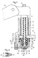
- Fig. 1 in schematischer Darstellung einen Schnitt durch eine Wischerwelle mit einem Anschlußstück,
- Fig. 2 einen Teilschnitt entlang der Linie 11,
- Fig. 3 einen Teilschnitt eines anderen Ausführungsbeispieles,
- Fig. 4 einen Teilschnitt entlang der Schnittlinie IV,
- Fig. 5 einen Teilschnitt eines weiteren Ausführungsbeispieles,
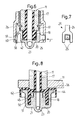
- Fig. 6 einen Teilschnitt eines weiteren Ausführungsbeispieles,
- Fig. 7 eine Ansicht in Pfeilrichtung P auf das Ausführungsbeispiel nach Fig.6
- Fig. 8 einen Teilschnitt durch ein weiteres Ausführungsbeispiel,
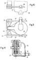
- Fig. 9 eine Ansicht auf ein weiteres Ausführungsbeispiel,
- Fig. 10 eine Seitenansicht der Ausführung nach Fig. 9.
- Fig. 11 einen Schnitt durch ein weiteres Ausführungsbeispiel,
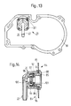
- Fig. 12 einen Schnitt durch ein Ausführungsbeispiel einer aus einem Getriebegehäuse herausragenden Wischerwelle,
- Fig. 13 eine Ansicht auf den Getriebegehäusedeckel,
- Fig. 14 in vergrößertem Maßstab einen Schnitt durch ein Anschlußstück,
- Fig. 15 einen Schnitt durch eine Halteplatte für das Anschlußstück,
- Fig. 16 eine Ansicht in Pfeilrichtung P auf diese Halteplatte,
- Fig. 17 einen Haltezapfen dieser Halteplatte,
- Fig. 18 einen Schnitt durch das Anschlußstück,
- Fig. 19 eine Ansicht in Pfeilrichtung P1 und
- Fig. 20 einen Teilschnitt entlang der Schnittlinie XX in Fig. 19.
- Zu einer Scheibenreinigungsanlage eines Kraftfahrzeuges gehört üblicherweise ein Wischhebel, von dem in Fig. 1 lediglich der Wischarm 10 angedeutet ist. Dieser Wischarm ist am Ende einer Wischerwelle 11 befestigt, die in einer Lagerbuchse 12 drehbar gelagert ist. Die Wischerwelle wird über ein geeignetes Getriebe, zu dem eine Schwinge 13 gehört, die am antriebsseitigen Ende an der Wischerwelle 11 drehfest fixiert ist, pendelnd angetrieben. Derartige Konstruktionen sind hinlänglich bekannt und weitere Erläuterungen dürften sich daher erübrigen.
- Zu den Scheibenreinigungsanlagen moderner Kraftfahrzeuge gehört üblicherweise auch eine Waschanlage, über die Waschflüssigkeit auf die zu reinigende Scheibe gespritzt wird. Bei der vorliegenden Erfindung wird diese Waschflüssigkeit durch eine axiale Bohrung in der Wischerwelle zu einer Düse 16 gefördert. Dabei dient also als Waschflüssigkeitsleitung entweder direkt die axiale Bohrung 15 in der Wischerwelle 11 oder ein Rohrstuck 17, das in diese Bohrung 15 eingesteckt, gegebenenfalls auch direkt eingespritzt ist. Dabei ist auf das eine Ende dieses Rohrstückes 17 die Düse 16 aufgesteckt, was normalerweise keine Probleme bereitet, weil an dieser Stelle keine Relativbewegung zwischen den zwei zu verbindenden Teilen, also der Düse 16 und dem Rohrstück 17, stattfindet. Am anderen Ende taucht ein Endstück 18 dieses als Waschflüssigkeitsleitung anzusehenden Rohrstückes 17 axial in ein insgesamt mit 20 bezeichnetes Anschlußstück hinein, das gegen Verdrehung gesichert ist. Hier findet also eine Relativbewegung zwischen dem Endstück 18 der Waschflüssigkeitsleitung 17 und diesem Anschlußstück 20 statt, und es muß daher besonders auf eine auch nach einer längeren Betriebszeit noch einwandfreie Abdichtung an dieser Stelle geachtet werden.
- Das Anschlußstück 20 ist insgesamt topfförmig ausgebildet und hat einen am Boden 21 angeordneten, radial abstehenden Anschlußstutzen 22 mit einem Zufuhrkanal 23 für die Waschflüssigkeit. Von dem Anschlußstück 20 steht außerdem radial ein gabelartiger Ansatz 24 mit zwei Zinken 25 am Ende ab, die ein insgesamt mit 26 bezeichnetes Halteelement umgreifen, das einstückig axial von der Lagerbuchse 12 absteht. Das Anschlußstück 20 ist axial auf das Endstück 18 der Waschflüssigkeitsleitung 17 aufgesteckt, wobei ein als Blattfeder 30 ausgebildetes Federelement dieses Anschlußstück 20 in axialer Richtung sichert. Bei dem Ausführungsbeispiel nach Fig. 1 ist diese Blattfeder über eine Klammer 31 direkt an dem ortsfesten Halteelement 26 festgelegt und greift zentrisch am Boden 21 des Anschlußstückes 20 an.
- Insgesamt kann daher zu Fig. 1 festgestellt werden, daß das Anschlußstück 20 verspannungsfrei unmittelbar am Endstück 18 der Waschflüssigkeitsleitung 17 zentriert ist. Dieses Anschlußstück kann nämlich beispielsweise bei einer Unwucht in der Wischerwelle in allen Richtungen in einer Ebene quer zur Wischerwelle wenigstens in einem bestimmten Maße diese Taumelbewegung der Wischerwelle mitmachen. Dies liegt daran, daß dieses Anschlußstück 20 nicht starr an einem ortsfesten Teil fixiert ist, sondern daß die Haltemittel gewissermaßen flexibel ausgebildet sind. Die zur Verdrehsicherung dienenden Elemente, nämlich der gabelartige Ansatz 24 mit den Zinken 25 sowie das Halteelement 26 lassen nämlich einen Ausgleich von denkbaren Toleranzen in einer Richtung radial zur Symmetrieachse S von Wischerwelle und Anschlußstück 20 zu. Auf diese Weise ist eine weitgehend verschleißfreie Verbindung zwischen dem verdrehsicher gehaltenen Anschlußstück 20 und dem sich drehenden Endstück 18 der Waschflüssigkeitsleitung 17 geschaffen.
- Bei der Ausführung nach Fig. 1 geht vom Boden 21 des topfförmigen Anschlußstückes 20 zentrisch ein zylindrischer Ansatz 40 aus, der eine Bohrung 41 als Waschflüssigkeitskanal aufweist. Zwischen diesem zylindrischen Ansatz 40 und der Seitenwand 42 ist ein Ringraum 43 gebildet, in den ein axial vom Endstück 18 der Waschflüssigkeitsleitung 17 abstehender Ringflansch 44 passend eingreift. Zwischen diesem Ringflansch 44 und der Seitenwand 42 ist eine Radialdichtung mittels eines O-Ringes 45 realisiert. Die Stirnflache 46 an diesem Ringflansch 44 dient dabei als Abstützfläche, an der das Anschlußstück 20 aufgrund der Federwirkung des Federelementes 30 dichtend anliegt. Bei der Ausführung nach Fig. 1 steht von der Stirnfläche des Anschlußstückes 20 eine Dichtlippe 47 axial ab, die an einem Radialflansch 48 am Endstück 18 der Waschflüssigkeitsleitung 17 dichtend anliegt. Von diesem Radialflansch 48 geht axial ein Ringflansch 49 aus, der kragenartig die Dichtlippe 47 übergreift.
- Aus Fig. 1 ist erkennbar, daß zwischen dem ortsfesten Anschlußstück 20 und dem Endstück 18 der Waschflüssigkeitsleitung 17 mehrere Abdichtflächen gebildet sind. Eine erste Dichtfläche ist geschaffen zwischen dem Boden des Anschlußstückes 20 und der Abstutzfläche 46 am Endstück 18 der Waschflüssigkeitsleitung. Eine zweite Abdichtung wird über den O-Ring 45 relaisiert. Eine Abdichtung erfolgt natürlich auch im Bereich der Lagerflächen 50 und 51 zwischen dem Endstück 18 der Waschflüssigkeitsleitung 17 und dem Anschlußstuck 20. Schließlich erfolgt eine Abdichtung durch die Dichtlippe 47 am Radialflansch 48. Auf diese Weise wird sichergestellt, daß auch bei einem hohen Förderdruck keine Waschflüssigkeit an der Verbindungsstelle zwischen dem Anschlußstück 20 und dem Waschflüssigkeitskanal 17 in der Wischerwelle 11 austritt. Dabei ist beachtet, daß die eingefetteten Lagerflächen 51 einerseits durch den Dichtring 45 gegenüber der Waschflüssigkeit und andererseits durch die Dichtlippe 47 auch gegenüber Schmutzwasser abgedichtet ist.
- Das Ausführungsbeispiel gemäß den Fig. 3 und 4 unterscheidet sich hinsichtlich der Ausbildung der Verdrehsicherung mittels eines gabelförmigen Ansatzes 24 und einem Halteelement 26 nicht vom Ausführungsbeispiel nach Fig.1 und 2. Bei dieser Ausführung nach Fig. 3 ist jedoch das Federelement 30 als winklig abgebogene Blattfeder ausgebildet, deren einer Schenkel 33 in einem parallel zur Wischerwelle 11 verlaufenden Schlitz 27 in dem ortsfesten Halteelement 26 steckt und dort verrastet ist. Der andere Schenkel 34 greift wiederum im wesentlichen zentrisch am Boden 21 des Anschlußstückes 20 an, wobei wiederum darauf geachtet ist, daß dieses Federelement 30 eine Bewegung des Anschlußstückes 20 in einer Ebene quer zur Wischerwelle nicht beeinträchtigt. Dazu hat dieses Federelement 30 am Ende eine ballige Erhebung 35, die mit einem ebenfalls ballig ausgebildeten Ansatz 29 am Anschlußstück 20 derart zusammenwirkt, daß eine im wesentlichen nur punktförmige Anlage gegeben ist. Bei der Ausführung nach Fig. 1 greift dagegen dieser Ansatz 29 in eine ballige Einbuchtung 32 am Endbereich des Federelementes 30 ein, die natürlich so ausgelegt werden muß, daß eine Relativbewegung möglich ist. Bei der Ausführung nach Fig. 3 ragt der Endabschnitt der Wischerwelle 11 in das topfförmige Anschlußstück 20 hinein, was die Stabilität der Anordnung erhöht. Der Sachverhalt kann auch so ausgedrückt werden, daß das Endstück 18 des Rohrstückes 17 den Endbereich der Wischerwelle 11 topfartig umgibt, wobei eine Lagerfläche 50 nur zwischen diesem Endstück 18 und dem Anschlußstück 20 gebildet ist. Da das Endstück 18 des Waschflüssigkeitskanales 17 und dieses Anschlußstück 20 aus Kunststoff herstellt sind, ist eine verschleißfreie Lagerpaarung durch Auswahl entsprechender Werkstoffe möglich. Im übrigen unterscheidet sich das Ausführungsbeispiel nach Fig. 3 von der Ausführung nach Fig. 1 noch dadurch, daß nun ein weiterer O-Ring 55 vorgesehen ist, der als Dichtung zwischen dem Radialflansch 48 am Endstück 18 der Waschflüssigkeitsleitung 17 und einem Radialflansch 56 am Anschlußstück 20 wirkt. Die beiden durch die O-Ringe 45, 55 gebildeten Dichtungen liegen in axialem Abstand voneinander entfernt, wobei zwischen diesen beiden Dichtungen eine Lagerfläche 51 zwischen dem Endstück 18 der Waschflussigkeitsleitung 17 und dem Anschlußstück 20 vorhanden ist, die gefettet werden kann, denn ein Auslaufen dieses Fettes bzw. eine Berührung dieses Fettes mit der Waschflüssigkeit ist ausgeschlossen.
- Fig. 5 unterscheidet sich von dem Ausführungsbeispiel nach Fig. 3 lediglich durch eine andere Anordnung des Federelementes 30, das wiederum als Blattfeder ausgebildet ist und um eine Achse parallel zur Wischerwlle schwenkbar an der Stirnfläche 57 des Ansatzes oder Halteelementes 26 fixiert, im gezeigten Ausführungsbeispiel verschraubt ist.
- Bei dem Ausführungsbeispiel nach den Fig. 6 und 7 sind an das Anschlußstück 20 mehrere in radialer Richtung federnde Lappen 58 angeformt, von denen in der Zeichnung nur einer ersichtlich ist. Über diesen Lappen 58 ist das Anschlußstück in axialer Richtung an dem ortsfesten Ansatz 26 abgestützt. Dazu hat dieser Lappen 58 eine Rastnase 59, die beim Aufstecken des Anschlußstückes 20 auf das Endstück 18 der Waschflüssigkeitsleitung 17 hinter einen Anschlag 60 einer Aussparung einrastet. Damit kann ein zusätzliches Federelement in Form einer Blattfeder entfallen. Über diesen Lappen 58 kann zugleich die Verdrehsicherung gebildet werden, doch kann man auch zusätzliche Halteelemente vorsehen, die zwischen die Zinken 25 eines in axialer Richtung von der Lagerbuchse 12 abstehenden Ansatzes 26 greifen. Bei dieser Ausführung ist im übrigen die Schwinge 13 nahe dem abtriebsseitigen Ende der Wischerwelle an dieser fixiert, so daß dieser Ansatz 26 am antriebsseitigen Ende als umlaufender Kragen ausgebildet sein kann, der folglich das Anschlußstück 20 in radialer Richtung gegen äußere Einflüsse schützt. Im übrigen wird zur Ausführung nach Fig. 6 noch darauf hingewiesen, daß nunmehr das Anschlußstück 20 eine von deren Stirnfläche ausgehende Dichtlippe 61 aufweist, die unmittelbar am Endbereich der Wischerwelle 11 und nicht am Endstück 18 des Waschflüssigkeitskanales 17 anliegt. Während bei den bisherigen Ausführungen also das Anschlußstück ausschließlich mit dem Endstück des Waschflüssigkeitskanales in Berührung steht, ist nun bei der Ausführung nach Fig. 6 ein Kontakt zwischen diesem Anschlußstück 20 und der Wischerwelle 11 direkt gegeben. Bei diesem Ausführungsbeispiel ist also die Seitenwand 42 des Anschlußstückes 20 gewissermaßen über das Endstück 18 und einen Teilbereich der Wischerwelle 11 gestülpt.
- Fig. 8 zeigt ein Ausführungsbeispiel mit einer anderen Ausbildung der einzelnen Dichtungen. Der O-Ring 45 ist nun nicht in der Nähe des Bodens 21 des Anschlußstückes 20, sondern nahe dem Ende der Wischerwelle 11 angeordnet. Als axiale Anlauffläche dient bei dieser Ausführung einerseits der Radialflansch 56 und andererseits der Ringflansch 44 am Anschlußstück 20. Anstelle des O-Ringes 55 bei der Ausführung nach Fig. 3 ist jetzt aber eine axial abstehende Dichtlippe 62 vorgesehen. Wiederum sind die beiden Abdichtungen über den O-Ring 45 und diese Dichtlippe 62 im Abstand voneinander angeordnet, so daß dazwischen gefettete Lagerflächen 50, 51 gebildet werden. Dabei ist bewußt darauf geachtet, daß der Durchmesser des O-Ringes 45 verhältnismäßig klein ist, damit die darauf einwirkende Axialkraft durch den Druck der über den Zufuhrkanal 23 einströmenden Waschflüssigkeit klein bleibt.
- Bei dem Ausführungsbeispiel gemäß den Fig. 9 und 10 wird anstelle einer Blattfeder ein im wesentlichen U-förmiger Drahtbügel 65 als Federelement verwendet. Dieser Drahtbügel 65, dessen Steg 66 an dem ortsfesten Ansatz 26 fixiert ist, greift mit seinen freien Schenkeln 67 an diametral gegenüberliegenden Haltezapfen 68 an der Mantelfläche des Anschlußstückes 20 an. Ein solches Federelement kann kostengünstig hergestellt und montiert werden.
- Bei dem Ausführungsbeispiel nach Fig. 11 greift ein als Verdrehsicherung dienender Haltebügel 70 an dem Anschlußstutzen 22 des Anschlußstückes 20 an, also in einem verhältnismäßig großen Abstand von der Symmetrieachse S. Als Federelement zur axialen Abstützung des Anschlußstückes 20 dient wiederum eine Blattfeder 30, die nun an diesem Haltebügel 70 fixiert ist. Im übrigen zeigt dieses Ausführungsbeispiel erneut, daß das Anschlußstück 20 über das Endstück 18 des Waschflüssigkeitskanales 17 und zusätzlich über den Endbereich der Wischerwelle 11 unmittelbar gestülpt ist.
- Die bisher gezeigten Ausführungsbeipiele beziehen sich auf Scheibenreinigungsanlagen, bei denen die Wischerwelle unbhängig vom Antriebsmotor bzw. dessen Getriebe in einem Kraftfahrzeug montiert wird. In den Fig. 12 bis 20 ist nun ein Ausführungsbeispiel dargestellt, bei dem das Endstück 18 der Waschflüssigkeitsleitung 17 durch eine Bohrung 80 in einem Getriebegehäusedeckel 81 hindurchragt, wobei das Anschlußstück 20 auf der dem Getriebe, von dem ein mit der Wischerwelle 11 drehfest verbundenes Zahnrad 82 ersichtlich ist, abgewandten Außenseite 83 angeordnet ist. Bei einer solchen Ausführung muß nicht nur darauf geachtet werden, daß zwischen der Wischerwelle 11 bzw. dem Endstück 18 des Waschflüssigkeitskanales 17 eine einwandfreie Abdichtung gegeben ist, sondern es muß auch eine solche Konstruktion gewählt werden, daß das Getriebe, also das Zahnrad 82, gegen äußere Einflüsse geschützt ist. Insbesondere muß man auch verhindern, daß eventuelles Fett aus dem Getriebegehäuse nach außen abfließen kann, weil sonst die Funktionsfähigkeit der Scheibenreinigungsanlage beeinträchtigt wird. Das bedeutet also, daß die Bohrung 80 im Getriebegehäusedeckel 81 abgedichtet werden muß, wobei natürlich im Sinne der vorliegenden Erfindung eine Konstruktion zu wählen ist, die eine verspannungsfreie Zentrierung des Anschlußstückes 20 auf der Wischerwelle 11 bzw. dem Endstück 18 des Waschflüssigkeitskanales 17 nicht behindert.
- Auf der Innenseite 84 des Getriebegehäusedeckels 81 ist eine im wesentlichen quadratische Halteplatte 85 angeordnet, die senkrecht abstehende Haltezapfen 86 aufweist, die durch entsprechende Durchbrüche 87 im Getriebegehäusedeckel 81 hindurchragen. Diese Haltezapfen 86 dienen als Befestigungsmittel für das Anschlußstück 20, was später noch erläutert wird. Von der Halteplatte 85 steht außerdem zentrisch eine Buchse 88 ab, die die Bohrung 80 in dem Getriebegehäusedeckel 81 durchsetzt. Wichtig ist dabei, daß der Durchmesser DB dieser Buchse kleiner ist als der Durchmesser D der Bohrung 80, so daß die Halteplatte 85 quer zur Waschflüssigkeitsleitung verschiebbar ist. Dazu müssen natürlich auch die Durchbrüche 87 größer sein als der Querschnitt der Haltezapfen 86 in dem Bereich, so daß also auch diese Haltezapfen 86 mit seitlichem Spiel durch diese Durchbrüche 87 hindurchragen. Insbesondere aus Fig. 15 und 16 geht hervor, daß von der Außenseite dieser Buchse 88 Rasthaken 89 abstehen, die ebenfalls als Befestigungsmittel für das Anschlußstück 20 dienen. Insgesamt sind vier derartige Rasthaken 89 vorgesehen, die gleichmäßig über den Umfang der Buchse verteilt sind.
- Das Anschlußstück 20 hat eine Ringflansch 90 mit Aufnahmelöchern 91 für die Haltezapfen 86. In der Seitenwand des Anschlußstückes 20 sind gleichmäßig am Umfang verteilt vier Aussparungen 92 vorgesehen, die mit den Rasthaken 89 an der Halteplatte 85 zusammenwirken.
- Die Baueinheit aus Getriebe und Wischerwelle wird wie folgt montiert. Zunächst wird die Halteplatte 85 am Getriebegehäusedeckel 81 vormontiert, wobei die Haltezapfen 86 durch die Durchbrüche 87 hindurchgreifen und mit ihren dann wieder auseinanderspreizenden Rastzungen die Halteplatte 85 am Getriebegehäusedeckel 81 halten. Auf die Außenseite 83 des Getriebegehäusedeckels wird dann eine Dichtung 96 aufgelegt. Dann wird das Anschlußstück 20 aufgesetzt, wobei die Haltezapfen 86 dann in die Aufnahmelöcher 91 eingreifen und die Rasthaken 89 in die Aussparungen 92 einrasten. Durch diese Befestigungsmittel, also die Rasthaken 89 und die Aussparungen 92 bzw. die Haltezapfen 86 und die Durchbrüche 87, wird das auf der Außenseite 83 angeordnete Anschlußstück 20 mit der auf der Innenseite 84 angeordneten Halteplatte 85 derart verrastet, daß die Teile unter Zwischenlage des Dichtringes 96 mit geringer Spannung am Getriebegehäusedeckel von gegenüberliegenden Seiten her anliegen. Durch geeignete Dimensionierung der Befestigungselemente kann man erreichen, daß die Bohrung 80 und die Durchbrüche 87 im Getriebegehäusedeckel 81 ausreichend abgedichtet sind, daß aber dennoch die Beweglichkeit von Halteplate 85 und Anschlußstück 20 in einer Ebene quer zur Wischerwelle bzw. parallel zum Getriebegehäusedeckel 81 nicht beeinträchtigt wird. Auch bei dieser Ausführung ist also das Anschlußstück verspannungsfrei gegenüber dem Endstück 18 der Waschflüssigkeitsleitung 17 zentriert. Eine Verdrehsicherung, die einen Ausgleich von Toleranzen in radialer Richtung zuläßt, wird durch das Zusammenwirken von Haltezapfen 86 und Durchbruch 87 realisiert.
- Im übrigen wird zu dieser Ausführung noch darauf hingewiesen, daß die Buchse 88 an der Halteplatte 85 direkt als Lagerbuchse für die Wischerwelle 11 dient. Das bedeutet also, daß auch die Halteplatte 85 verspannungsfrei zentriert an der Wischerwelle 11 bzw. dem Endstück 18 des Waschflüssigkeitskanals 17 gelagert ist. Insbesondere aus Fig. 14 geht hervor, daß diese Lagerbuchse 88 in die topfartige Aufnahme am Anschlußstück 20 hineinragt, wobei zwischen der Stirnfläche 97 dieser Lagerbuchse 88 und einem Ansatz 98 am Anschlußstück 20 ein axial wirkendes Dichtelement 99 vorgesehen ist, das eine Dichtlippe 100 aufweist, die radial am Enstück 18 der Waschflüssigkeitsleitung 17 anliegt. Von der Stirnfläche 97 der Buchse 88 steht ein Kragen 101 ab, der diese Dichtlippe 100 unterstützt, so daß auch bei hohen Betriebsdrücken eine einwandfreie Dichtwirkung erreicht wird.
- Aus Fig. 12 wird deutlich, daß zwei Lagerflächen 50, 51 vorhanden sind, wobei eine Lagerfläche 50 mit der Wischerwelle 11 und eine Lagerfläche 51 mit dem Endstück 18 der Waschflüssigkeitsleitung 17 zusammenwirkt. Insgesamt kann diese Konstruktion auch in der Weise beschrieben werden, daß das Anschlußstück 20 zweiteilig ausgebildet ist, wobei die beiden Teile 85, 20 zwischen sich den Getriebegehäusedeckel 81 aufnehmen und drehfest und verschiebefest miteinander verrastet sind. An beiden Teile befinden sich Lagerflächen, wobei eine Lagerfläche mit der Wischerwelle und eine Lagerfläche mit dem Waschflüssigkeitskanal zentriert ist.
- Insbesondere aus Fig. 12 geht noch hervor, daß auch über einen O-Ring 102 eine zusätzliche Abdichtung zwischen der Halteplatte 85 und der Wischerwelle 11 möglich ist, wodurch ein Auslaufen des Getriebefettes verhindert wird.
- In Fig. 1 ist im übrigen noch angedeutet, daß in das Anschlußstück 20 ein Rückschlagventil 110 integriert werden kann. Auf einer Stirnfläche 111 des zentrisch vom Boden 21 des Anschlußstückes 20 abstehenden und mit einer Axialbohrung 41 versehenen Ansatzes 40 ist ein Ventilsitz für ein Ventilschließglied in Form einer Kugel 114 ausgebildet. Eine Ventilschließfeder 115 stützt sich zentrisch an einer Ringschulter 116 am Rohrstück 17 ab und drückt das Ventilschließglied 114 auf seinen Ventilsitz.
- Durch dieses Rückschlagventil wird in an sich bekannter Weise ein Leerlaufen der Waschflüssigkeitsleitung verhindert.
- Abschließend wird nochmals darauf hingewiesen, daß mit den Merkmalen der vorliegenden Erfindung eine verschleißarme Verbindung zwischen dem sich drehenden Endstück der Wischerwelle und dem drehfesten Anschlußstück geschaffen ist, die eine lange Lebensdauer erreicht.
Claims (38)
Applications Claiming Priority (3)
| Application Number | Priority Date | Filing Date | Title |
|---|---|---|---|
| DE3907962 | 1989-03-11 | ||
| DE19893907962 DE3907962C2 (de) | 1989-03-11 | 1989-03-11 | Scheibenreinigungsanlage, insbesondere für Kraftfahrzeuge |
| PCT/EP1990/000345 WO1990010562A1 (de) | 1989-03-11 | 1990-03-02 | Scheibenreinigungsanlage, insbesondere für kraftfahrzeuge |
Publications (3)
| Publication Number | Publication Date |
|---|---|
| EP0414873A1 EP0414873A1 (de) | 1991-03-06 |
| EP0414873B1 true EP0414873B1 (de) | 1994-06-01 |
| EP0414873B2 EP0414873B2 (de) | 1999-03-03 |
Family
ID=6376131
Family Applications (1)
| Application Number | Title | Priority Date | Filing Date |
|---|---|---|---|
| EP19900904304 Expired - Lifetime EP0414873B2 (de) | 1989-03-11 | 1990-03-02 | Scheibenreinigungsanlage, insbesondere für kraftfahrzeuge |
Country Status (7)
| Country | Link |
|---|---|
| US (1) | US5195206A (de) |
| EP (1) | EP0414873B2 (de) |
| JP (1) | JPH03504589A (de) |
| BR (1) | BR9005771A (de) |
| DE (1) | DE3907962C2 (de) |
| ES (1) | ES2054345T5 (de) |
| WO (1) | WO1990010562A1 (de) |
Families Citing this family (15)
| Publication number | Priority date | Publication date | Assignee | Title |
|---|---|---|---|---|
| FR2674489B1 (fr) * | 1991-03-29 | 1995-08-04 | Valeo Systemes Dessuyage | Dispositif de lave-glace, notamment pour vehicule automobile. |
| DE4117107B4 (de) * | 1991-05-25 | 2006-02-16 | Itt Automotive Europe Gmbh | Scheibenreinigungsanlage, insbesondere für Kraftfahrzeuge |
| FR2722463B1 (fr) * | 1994-07-13 | 1996-08-23 | Valeo Systemes D Essuyage Sa | Dispositif de lave-glace, notamment pour vehicule automobile |
| FR2762273B1 (fr) * | 1997-04-22 | 1999-07-02 | Valeo Systemes Dessuyage | Motoreducteur pour essuie-glace de vehicule automobile avec un conduit de liquide de nettoyage |
| DE19946632A1 (de) * | 1999-09-29 | 2001-04-05 | Volkswagen Ag | Scheibenwischeranlage für ein Fahrzeug |
| DE19946631A1 (de) * | 1999-09-29 | 2001-04-05 | Volkswagen Ag | Scheibenwischeranlage für Fahrzeuge |
| DE10209418B4 (de) * | 2002-03-05 | 2016-02-11 | Continental Automotive Gmbh | Reinigungsvorrichtung zur Reinigung einer Scheibe eines Kraftfahrzeuges |
| DE102004014078B4 (de) * | 2004-03-23 | 2021-01-14 | Valeo Wischersysteme Gmbh | Scheibenwischeranlage |
| CN101331354A (zh) * | 2005-12-16 | 2008-12-24 | 卡尔·赖纳有限责任公司 | 用于与管状件连接的连接元件 |
| DE102009051021A1 (de) | 2009-10-28 | 2011-05-05 | Valeo Wischersysteme Gmbh | Wischwelle für Scheibenwischanlagen von Fahrzeugen sowie Scheibenwischanlage mit einer solchen Wischwelle |
| DE102012222038B4 (de) | 2012-12-03 | 2025-02-06 | Continental Automotive Technologies GmbH | Hydraulisches Reinigungssystem |
| KR101417490B1 (ko) * | 2012-12-18 | 2014-07-08 | 현대자동차주식회사 | 자동차용 워셔액 공급 장치 |
| FR3003219B1 (fr) * | 2013-03-14 | 2016-11-18 | Valeo Systemes Dessuyage | Dispositif de distribution de liquide lave-glace de balais d'essuie-glace de vehicule automobile |
| JP6257341B2 (ja) * | 2014-01-16 | 2018-01-10 | 株式会社ミツバ | ノズルおよびその製造方法並びにウォッシャノズル |
| JP2016088319A (ja) * | 2014-11-06 | 2016-05-23 | 株式会社ミツバ | ワイパモータ |
Family Cites Families (16)
| Publication number | Priority date | Publication date | Assignee | Title |
|---|---|---|---|---|
| US933290A (en) * | 1908-08-31 | 1909-09-07 | William J Clay | Reel-operated hydrant. |
| US2483243A (en) * | 1944-02-11 | 1949-09-27 | Productive Inventions Inc | Fluid transmission connection for cleaner wipers |
| US2679434A (en) * | 1951-05-31 | 1954-05-25 | Vineent M Idziak | Safety reel with automatic valve |
| US3129960A (en) * | 1959-10-01 | 1964-04-21 | Reimers Getriebe Kg | Device for feeding pressure fluids from a stationary bearing cover into the outer end of a rotating shaft |
| US3591206A (en) * | 1969-04-01 | 1971-07-06 | Paul S Giovagnoli | Rotary water distributor for rotatable spray assembly |
| US3760451A (en) * | 1971-11-30 | 1973-09-25 | M Steed | Combination windshield wiper and washer |
| US3887956A (en) * | 1973-10-18 | 1975-06-10 | Lescoa Inc | Windshield wiper fluid dispenser |
| US4313624A (en) * | 1980-06-06 | 1982-02-02 | Zierden Company | Swivel cartridge |
| DE8100709U1 (de) * | 1981-01-15 | 1982-07-01 | Robert Bosch Gmbh, 7000 Stuttgart | Reinigungsvorrichtung fuer scheiben von kraftfahrzeugen |
| DE3102538C1 (de) * | 1981-01-27 | 1982-11-11 | Ford-Werke AG, 5000 Köln | Scheibenwischerarm mit Wascherduese fuer Kraftfahrzeugscheiben |
| JPS57194140A (en) * | 1981-05-25 | 1982-11-29 | Mazda Motor Corp | Wind washer for car |
| DE3521024C2 (de) * | 1984-06-20 | 1994-12-08 | Volkswagen Ag | Scheibenreinigungsvorrichtung für Fahrzeuge |
| JPS61247543A (ja) * | 1985-04-05 | 1986-11-04 | Takeo Isaka | ウインド洗滌液噴出機構を有するワイパ−ア−ム作動軸ボルトに装着する流体継手 |
| DE3523441A1 (de) * | 1985-06-29 | 1987-01-08 | Swf Auto Electric Gmbh | Scheibenwischeranlage |
| DE3632734A1 (de) * | 1986-09-26 | 1988-03-31 | Swf Auto Electric Gmbh | Scheibenreinigungsanlage, insbesondere fuer kraftfahrzeuge |
| DE3643476A1 (de) * | 1986-12-19 | 1988-06-30 | Swf Auto Electric Gmbh | Scheibenreinigungsanlage |
-
1989
- 1989-03-11 DE DE19893907962 patent/DE3907962C2/de not_active Expired - Lifetime
-
1990
- 1990-03-02 US US07/623,375 patent/US5195206A/en not_active Expired - Lifetime
- 1990-03-02 ES ES90904304T patent/ES2054345T5/es not_active Expired - Lifetime
- 1990-03-02 JP JP2504171A patent/JPH03504589A/ja active Pending
- 1990-03-02 EP EP19900904304 patent/EP0414873B2/de not_active Expired - Lifetime
- 1990-03-02 BR BR9005771A patent/BR9005771A/pt not_active IP Right Cessation
- 1990-03-02 WO PCT/EP1990/000345 patent/WO1990010562A1/de not_active Ceased
Also Published As
| Publication number | Publication date |
|---|---|
| WO1990010562A1 (de) | 1990-09-20 |
| DE3907962C2 (de) | 1998-07-09 |
| ES2054345T3 (es) | 1994-08-01 |
| US5195206A (en) | 1993-03-23 |
| EP0414873A1 (de) | 1991-03-06 |
| EP0414873B2 (de) | 1999-03-03 |
| BR9005771A (pt) | 1991-08-06 |
| DE3907962A1 (de) | 1990-09-13 |
| ES2054345T5 (es) | 1999-07-01 |
| JPH03504589A (ja) | 1991-10-09 |
Similar Documents
| Publication | Publication Date | Title |
|---|---|---|
| EP0414873B2 (de) | Scheibenreinigungsanlage, insbesondere für kraftfahrzeuge | |
| DE3907980C2 (de) | Scheibenreinigungsanlage | |
| EP0500868B1 (de) | Antriebsvorrichtung, insbesondere für scheibenwischer an kraftfahrzeugen | |
| EP0272480B1 (de) | Scheibenreinigungsanlage | |
| EP0207364B1 (de) | Scheibenwischeranlage | |
| DE19804135B4 (de) | Wischerlager | |
| DE3732069A1 (de) | Scheibenwischer mit verstellbarem schwenkwinkelbereich des wischerarms | |
| EP1718507B1 (de) | Scheibenwischanlage für fahrzeuge sowie befestigungselement für eine solche anlage | |
| DE3003297C2 (de) | Kraftfahrzeugscheinwerfer mit einer Stellvorrichtung für die Reflektorneigung | |
| DE112011103771B4 (de) | Schwenkkörper für Frontscheibenwischeranlage | |
| DE3907979C2 (de) | Scheibenreinigungsanlage | |
| EP1539546A1 (de) | Lagerung f r wischerantriebe | |
| EP0443662B1 (de) | Sprüharmlagerung bei einer Geschirrspülmaschine | |
| EP0549754A1 (de) | Elektromotor, insbesondere für eine scheibenwischanlage eines kraftfahrzeugs | |
| DE4408733A1 (de) | Wischarm für eine Scheibenwischeranlage, insbesondere für Kraftfahrzeuge | |
| DE2622437A1 (de) | Wischvorrichtung fuer scheiben von kraftfahrzeugen | |
| DE10331854B4 (de) | Korrosionsgeschütztes Wischerwellenlager | |
| DE3511811C2 (de) | Reinigungsvorrichtung, insbesondere für Scheiben von Kraftfahrzeugen | |
| DE3907967A1 (de) | Scheibenreinigungsanlage | |
| DE3632734A1 (de) | Scheibenreinigungsanlage, insbesondere fuer kraftfahrzeuge | |
| DE10040530A1 (de) | Wischvorrichtung, insbesondere für Kraftfahrzeuge | |
| DE4439436A1 (de) | Arretierelement mit einem Fluchtungsfehlerausgleich | |
| DE19521084B4 (de) | Wischerwelle für eine Scheibenwischeranlage, insbesondere eines Kraftfahrzeuges | |
| DE102004014078B4 (de) | Scheibenwischeranlage | |
| EP0864472B1 (de) | Antriebsvorrichtung, insbesondere für Scheibenwischer an Kraftfahrzeugen |
Legal Events
| Date | Code | Title | Description |
|---|---|---|---|
| PUAI | Public reference made under article 153(3) epc to a published international application that has entered the european phase |
Free format text: ORIGINAL CODE: 0009012 |
|
| 17P | Request for examination filed |
Effective date: 19901113 |
|
| AK | Designated contracting states |
Kind code of ref document: A1 Designated state(s): ES FR GB IT SE |
|
| 17Q | First examination report despatched |
Effective date: 19921215 |
|
| ITF | It: translation for a ep patent filed | ||
| GRAA | (expected) grant |
Free format text: ORIGINAL CODE: 0009210 |
|
| RAP1 | Party data changed (applicant data changed or rights of an application transferred) |
Owner name: ITT AUTOMOTIVE EUROPE GMBH |
|
| AK | Designated contracting states |
Kind code of ref document: B1 Designated state(s): ES FR GB IT SE |
|
| GBT | Gb: translation of ep patent filed (gb section 77(6)(a)/1977) |
Effective date: 19940609 |
|
| REG | Reference to a national code |
Ref country code: ES Ref legal event code: FG2A Ref document number: 2054345 Country of ref document: ES Kind code of ref document: T3 |
|
| ET | Fr: translation filed | ||
| EAL | Se: european patent in force in sweden |
Ref document number: 90904304.4 |
|
| PLBI | Opposition filed |
Free format text: ORIGINAL CODE: 0009260 |
|
| 26 | Opposition filed |
Opponent name: VALEO SYSTEMES D'ESSUYAGE Effective date: 19950301 |
|
| PLBQ | Unpublished change to opponent data |
Free format text: ORIGINAL CODE: EPIDOS OPPO |
|
| PLAB | Opposition data, opponent's data or that of the opponent's representative modified |
Free format text: ORIGINAL CODE: 0009299OPPO |
|
| R26 | Opposition filed (corrected) |
Opponent name: VALEO SYSTEMES D'ESSUYAGE Effective date: 19950301 |
|
| PLAW | Interlocutory decision in opposition |
Free format text: ORIGINAL CODE: EPIDOS IDOP |
|
| APAE | Appeal reference modified |
Free format text: ORIGINAL CODE: EPIDOS REFNO |
|
| APAC | Appeal dossier modified |
Free format text: ORIGINAL CODE: EPIDOS NOAPO |
|
| APAC | Appeal dossier modified |
Free format text: ORIGINAL CODE: EPIDOS NOAPO |
|
| PGFP | Annual fee paid to national office [announced via postgrant information from national office to epo] |
Ref country code: GB Payment date: 19970221 Year of fee payment: 8 |
|
| PG25 | Lapsed in a contracting state [announced via postgrant information from national office to epo] |
Ref country code: GB Free format text: LAPSE BECAUSE OF NON-PAYMENT OF DUE FEES Effective date: 19980302 |
|
| APAC | Appeal dossier modified |
Free format text: ORIGINAL CODE: EPIDOS NOAPO |
|
| PLAW | Interlocutory decision in opposition |
Free format text: ORIGINAL CODE: EPIDOS IDOP |
|
| GBPC | Gb: european patent ceased through non-payment of renewal fee |
Effective date: 19980302 |
|
| PUAH | Patent maintained in amended form |
Free format text: ORIGINAL CODE: 0009272 |
|
| STAA | Information on the status of an ep patent application or granted ep patent |
Free format text: STATUS: PATENT MAINTAINED AS AMENDED |
|
| 27A | Patent maintained in amended form |
Effective date: 19990303 |
|
| AK | Designated contracting states |
Kind code of ref document: B2 Designated state(s): ES FR GB IT SE |
|
| PGFP | Annual fee paid to national office [announced via postgrant information from national office to epo] |
Ref country code: SE Payment date: 19990326 Year of fee payment: 10 |
|
| ET3 | Fr: translation filed ** decision concerning opposition | ||
| ITF | It: translation for a ep patent filed | ||
| REG | Reference to a national code |
Ref country code: ES Ref legal event code: DC2A Kind code of ref document: T5 Effective date: 19990429 |
|
| PG25 | Lapsed in a contracting state [announced via postgrant information from national office to epo] |
Ref country code: SE Free format text: LAPSE BECAUSE OF NON-PAYMENT OF DUE FEES Effective date: 20000303 |
|
| EUG | Se: european patent has lapsed |
Ref document number: 90904304.4 |
|
| APAH | Appeal reference modified |
Free format text: ORIGINAL CODE: EPIDOSCREFNO |
|
| PGFP | Annual fee paid to national office [announced via postgrant information from national office to epo] |
Ref country code: ES Payment date: 20090323 Year of fee payment: 20 |
|
| PGFP | Annual fee paid to national office [announced via postgrant information from national office to epo] |
Ref country code: FR Payment date: 20090331 Year of fee payment: 20 Ref country code: IT Payment date: 20090319 Year of fee payment: 20 |
|
| REG | Reference to a national code |
Ref country code: ES Ref legal event code: FD2A Effective date: 20100303 |
|
| PG25 | Lapsed in a contracting state [announced via postgrant information from national office to epo] |
Ref country code: ES Free format text: LAPSE BECAUSE OF EXPIRATION OF PROTECTION Effective date: 20100303 |