EP0413693B1 - Construction de tunnels en beton arme - Google Patents
Construction de tunnels en beton arme Download PDFInfo
- Publication number
- EP0413693B1 EP0413693B1 EP89902764A EP89902764A EP0413693B1 EP 0413693 B1 EP0413693 B1 EP 0413693B1 EP 89902764 A EP89902764 A EP 89902764A EP 89902764 A EP89902764 A EP 89902764A EP 0413693 B1 EP0413693 B1 EP 0413693B1
- Authority
- EP
- European Patent Office
- Prior art keywords
- process according
- segments
- elements
- sheet steel
- concrete
- Prior art date
- Legal status (The legal status is an assumption and is not a legal conclusion. Google has not performed a legal analysis and makes no representation as to the accuracy of the status listed.)
- Expired - Lifetime
Links
Images

Classifications
-
- E—FIXED CONSTRUCTIONS
- E04—BUILDING
- E04H—BUILDINGS OR LIKE STRUCTURES FOR PARTICULAR PURPOSES; SWIMMING OR SPLASH BATHS OR POOLS; MASTS; FENCING; TENTS OR CANOPIES, IN GENERAL
- E04H9/00—Buildings, groups of buildings or shelters adapted to withstand or provide protection against abnormal external influences, e.g. war-like action, earthquake or extreme climate
- E04H9/04—Buildings, groups of buildings or shelters adapted to withstand or provide protection against abnormal external influences, e.g. war-like action, earthquake or extreme climate against air-raid or other war-like actions
- E04H9/10—Independent shelters; Arrangement of independent splinter-proof walls
- E04H9/12—Independent shelters; Arrangement of independent splinter-proof walls entirely underneath the level of the ground, e.g. air-raid galleries
-
- E—FIXED CONSTRUCTIONS
- E21—EARTH DRILLING; MINING
- E21D—SHAFTS; TUNNELS; GALLERIES; LARGE UNDERGROUND CHAMBERS
- E21D11/00—Lining tunnels, galleries or other underground cavities, e.g. large underground chambers; Linings therefor; Making such linings in situ, e.g. by assembling
-
- E—FIXED CONSTRUCTIONS
- E21—EARTH DRILLING; MINING
- E21D—SHAFTS; TUNNELS; GALLERIES; LARGE UNDERGROUND CHAMBERS
- E21D11/00—Lining tunnels, galleries or other underground cavities, e.g. large underground chambers; Linings therefor; Making such linings in situ, e.g. by assembling
- E21D11/04—Lining with building materials
- E21D11/05—Lining with building materials using compressible insertions
-
- E—FIXED CONSTRUCTIONS
- E21—EARTH DRILLING; MINING
- E21D—SHAFTS; TUNNELS; GALLERIES; LARGE UNDERGROUND CHAMBERS
- E21D11/00—Lining tunnels, galleries or other underground cavities, e.g. large underground chambers; Linings therefor; Making such linings in situ, e.g. by assembling
- E21D11/14—Lining predominantly with metal
- E21D11/18—Arch members ; Network made of arch members ; Ring elements; Polygon elements; Polygon elements inside arches
- E21D11/22—Clamps or other yieldable means for interconnecting adjacent arch members either rigidly, or allowing arch member parts to slide when subjected to excessive pressure
Definitions
- the invention relates to a method for expanding a tunnel with steel / concrete lining with an inner shell made of sheet steel segments. Subway tunnels are also considered to be such tunnels.
- a tunnel is usually only expanded if the surrounding mountains are not stable.
- the most common type of construction provides that a shotcrete layer is first applied to the eruption.
- the shotcrete layer changes the flaking of the rock layers. This is also known as consolidation.
- the shotcrete layer forms a reserve for commonly used plastic seals.
- the plastic seals are applied after the shotcrete layer has been completed.
- the seals are made up of sheets.
- the lining with the sealing is followed by the introduction of concrete reinforcements or reinforcing bars and / or mats.
- a formwork carriage is driven into the tunnel and the space between the sealing and the formwork carriage is filled with concrete. This is done in individual sections.
- the sections are usually up to 20 m long.
- Panel construction is common in tunnels where pressurized water is present.
- the panels are made of concrete and / or steel.
- Such constructions have not become established in areas with low water pressure or low water intake. This is due to the fact that concrete is still the cheaper building material compared to steel.
- Settling or lowering is one of the functions to be considered in tunnel construction.
- Experience has shown that mining and the associated cutting of mountain layers cause a fault in the mountains or in the ground.
- the result of the disturbance are tensions that are reduced by settling or subsidence.
- the object of the invention is to create a new type of tunnel construction which takes account of the tensions occurring in the mountains and / or fractures.
- DE-A-3613140 discloses a method for expanding a tunnel with a steel / concrete lining.
- an outer shell made of sheet steel.
- the internal arrangement of the sheet steel shell results in a completely new construction with surprising new procedures and advantageous effects.
- the steel sheet segment After pledging a steel sheet segment, the steel sheet segment will be backfilled with concrete as soon as possible. This results in the positive and positive locking of the steel sheet segment with the rock eruption. With a suitable early load-bearing strength of the concrete, pre-attachment is possible Mountain pressure has already been recorded. According to the invention, it is also provided that the steel sheet segments will be supported as soon as possible on the tunnel base in the region of the dismantling front. This support is provisional if the tunnel is broken out in sections and the calotte is started. Then, after the dome eruption and the expansion of the tunnel in the dome area, the dismantling in the area of the tunnel stope follows.
- this support is flexible. This is achieved through the resilience elements between the steel sheet segments and the support (e.g. the tunnel sole).
- the flexibility elements allow the rock to be deformed.
- the philosophy behind this is to create a fully or partially self-supporting arch formation by deforming the mountains above the tunnel. This relieves the tunnel expansion.
- the compliance in the area of the compliance elements requires a deformation cavity behind the compliance elements. Accordingly, the concrete is backfilled leaving the cavities free.
- the compliance elements then allow controlled compliance over the selected duration of their use.
- the compliance function may be interrupted if the breakout occurs for the bench.
- Steel sheet segments according to the invention which are supported on the tunnel sole by means of resilience elements, can in turn be used for the expansion in the rung area.
- the above-described interruption of the compliance function has only a minor influence on the settlement behavior or lowering behavior.
- the resilience can also be maintained during the outbreak.
- foundation strips are used as supports for the resilience elements of the steel segments on the calotte side chosen, which have sufficient hold in the mountains during the eruption of the rungs and / or find sufficient hold in the already completed tunnel construction.
- the deformation cavities can be kept open until any desired settlement behavior or relaxation of the rock has occurred.
- the compliance elements are then stiffened. This is preferably done by filling the deformation cavities with concrete. That can e.g. B. done by injecting concrete milk.
- the steel-concrete lining according to the invention with internal steel segments advantageously eliminates the need for an additional sealing measure if the steel plate segments according to the invention overlap. Then the overlap areas can be welded together. Tensioning with the interposition of joint tape can also be considered.
- the steel segments can be backfilled with concrete in various ways.
- One possibility is to blow the building material into the cavity between the steel segments and the rock eruption after the steel segments have been set up while being wetted with water.
- formwork can be dispensed with if the building material has an appropriate early strength.
- Such quickly binding or strengthening concretes are commercially available.
- Another possibility for shaping the concrete segments according to the invention is to use face formwork.
- the building material can be hydraulically pumped behind the face formwork.
- the front formwork prevents the building material from flowing out of the cavity between the steel segments and the rock eruption.
- the deformation cavity provided in the area of the compliance elements preferably extends from these compliance elements to the rock eruption.
- the cavity can also end at a distance from the eruption. In this case, however, the cavity is always chosen to be large enough to essentially maintain the resilience effect described above.
- the expansion according to the invention can be varied in many ways. It can be adjusted to the special requirements of the individual case.
- the setting of the expansion according to the invention is carried out either by changing the number of different segments and / or by changing the number of compliance elements.
- the expansion is also suitable as a modular system.
- corrugated steel sheets are preferably used as steel sheet segments.
- the steel sheet has particularly high resistance to bending. It is also advantageous to provide the steel sheet with building material anchors or reinforcing bars, which both establish a connection to the building material segment and also optionally reinforce the building material segment.
- the resilience elements can consist of plates, between which deformation profiles are provided.
- the design of the deformation profiles can be designed mathematically and constructively exactly to the desired flexibility.
- concrete has been used as a building material in tunnel construction.
- the invention is not limited to concrete.
- the term concrete is intended to encompass all building materials in question.
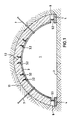
- Fig. 1 the outbreak for a tunnel dome and 2 denotes the bottom of the outbreak.
- the mountains are called 1.1. 1 consists of a steel inner shell 3 and a molded or backfilled concrete segment 1.2.
- the steel inner shell 3 is made of a corrugated steel sheet of, for. B. 2 - 5 mm thick.
- the inner shell 3 forms a sheet metal segment. Further sheet metal segments are arranged one behind the other in the longitudinal direction of the tunnel.
- shells with several sheet metal segments can also be used.
- the number of sheet metal segments can be varied in the longitudinal direction of the tunnel.
- the sheet metal segment 3 is provided with a number of evenly distributed building material anchors 3.2.
- the building material anchors 3.2 are welded. At the end facing away from the sheet metal, the building material anchors 3.2 have an angle.
- the building material anchors 3.2 serve to secure the connection between the segments 1.2 and 3 or to establish a connection.
- the inner shell 3 is introduced by means of a suitable removal platform or a front loader redesigned as a removal tool.
- the forehead area between the inner shell 3 and the rock 1.1 is closed with a front formwork. Furthermore, the cavity 6 is kept open behind the resilience elements with the aid of a suitable formwork body. As formwork body for the cavity 6 are such. B. inflatable pillow.
- the cavity is filled with concrete, so that the concrete segment 1.2 is created.
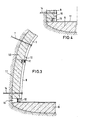
- the further excavation of the tunnel in the rung area according to FIG. 2 follows the expansion shown in FIG. 1.
- the concrete segment 1.2 is held in position with the inner shell 3 by means of anchors 7.
- the anchors 7 have either been placed directly when the inner shell 3 is attached or after concreting.
- Anchoring directly when inserting the inner shell 3 has the advantage that the anchors then hold the inner shell in position during the backfilling process.
- the sheet metal segments 9 have resilience elements, which are denoted here by 12 and are supported on the tunnel sole.
- a deformation cavity 13 is created behind the resilience elements 12.
- the deformation cavity 13 is created like the deformation cavity 6.
- the cavity behind the sheet metal segments 9 is then filled with concrete.
- the deformation cavity 6 is closed at the same time, since the concrete surrounds the resilience elements 5.1 and 5.2.
- FIG. 1 and 3 show two compliance phases, the compliance phase according to FIG. 1 corresponding to the progress of work in tunneling in the exemplary embodiment to max. limited to three days. During this time, significant mountain tensions have been balanced.
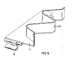
- the deformation cavity 13 is then filled with concrete. This is preferably done by spraying concrete milk. At the same time, the deformation cavity is closed with a corrugated metal strip 15 according to FIG. 4. The sheet metal strip 15 overlaps the segments 9 at 16. At the same time, a sole sheet 17 is provided in the sole area. As a result, all sheets 3, 9, 15 and 17 can be welded together. This creates a tight inner sheet metal shell.
- the resilience elements 5.1, 5.2 and 12 consist of M-shaped or W-shaped deformation profiles 18.
- the number of deformation profiles and their dimensions can vary.
- the flexibility of the flexibility elements can thus be set as desired.
- deformation profiles 18 and the plate 11 in the exemplary embodiment consist of the same steel sheet as the segments 3 and 9.
- other formwork bodies can also be used.
- the bodies can form a lost formwork, i. H. the bodies remain in place.
- the bodies for the formation of cavities are also made in one piece with the resilience elements or molded onto them.
- the shaped body forming the cavity can, for. B. arise from a sheet metal bulge.
- the compliance elements are provided with reinforcement bolts that improve the anchoring of the compliance elements in the concrete.
Abstract
Claims (14)
- Procédé de cuvelage d'un tunnel avec cuvelage acier/béton, comportant une coque interne en segments de tôle d'acier (3, 9), caractérisé en ce que dans au moins un tronçon de construction :- les segments de tôle d'acier (3, 9) sont posés élastiquement sur le fond du tronçon de construction,- les segments de tôle d'acier (3, 9) sont remplis par l'arrière avec du béton (1, 2) en maintenant libre un espace libre de tassement (6, 13) sur le fond du tronçon de construction, et- après fabrication du raccordement restant du cuvelage sur le fond du tronçon de construction ou sur le tronçon de construction suivant, la zone d'élasticité est rigidement remplie et les segments de tôle d'acier (3, 9) sont rendus étanches l'un par rapport à l'autre.
- Procédé suivant la revendication 1, caractérisé en ce que les segments de tôle d'acier (3, 9) sont posés avec des éléments d'élasticité sur un support (4, 8).
- Procédé suivant l'une ou l'autre des revendications 1 et 2, caractérisé en ce que la cavité de déformation est remplie avec un lait de béton.
- Procédé suivant la revendication 1, caractérisé en ce que lors d'un cuvelage en plusieurs étapes, les éléments successifs sont bétonnés sur les éléments achevés précédemment.
- Procédé suivant une ou plusieurs des revendications 1 à 4, caractérisé par des segments de tôle d'acier (3, 9) qui se recouvrent.
- Procédé suivant la revendication 5, caractérisé par une coque interne en acier fermée.
- Procédé suivant la revendication 6, caractérisé par des tôles d'acier soudées.
- Procédé suivant l'une ou plusieurs des revendications 1 à 7, caractérisé par un coffrage formant derrière les éléments d'élasticité la cavité de déformation.
- Procédé suivant la revendication 8, caractérisé par des corps de moulage réutilisables ou perdus.
- Procédé suivant la revendication 8, caractérisé par des corps de moulage qui sont façonnés sur les éléments d'élasticité ou qui forment une pièce avec ceux-ci.
- Procédé suivant l'une ou plusieurs des revendications 1 à 10, caractérisé en ce que les éléments d'élasticité sont pourvus de profilés de déformation (18) en forme de M ou de W.
- Procédé suivant la revendication 11, caractérisé en ce que les profilés de déformation sont situés derrière les segments de tôle.
- Procédé suivant l'une ou plusieurs des revendications 1 à 12, caractérisé par des chevilles d'armature sur les éléments d'élasticité.
- Procédé suivant l'une ou plusieurs des revendications 1 à 13, caractérisé par des barres de déplacement (3.2) ou par des ancrages de matériaux sur les segments (3, 9).
Priority Applications (1)
| Application Number | Priority Date | Filing Date | Title |
|---|---|---|---|
| AT89902764T ATE83296T1 (de) | 1988-02-26 | 1989-02-21 | Stahlbetonausbau fuer verkehrstunnel. |
Applications Claiming Priority (2)
| Application Number | Priority Date | Filing Date | Title |
|---|---|---|---|
| DE3806126A DE3806126A1 (de) | 1988-02-26 | 1988-02-26 | Geschlossener ausbau fuer insbesondere untertaegige grubenstrecken |
| DE3806126 | 1988-02-26 |
Publications (2)
| Publication Number | Publication Date |
|---|---|
| EP0413693A1 EP0413693A1 (fr) | 1991-02-27 |
| EP0413693B1 true EP0413693B1 (fr) | 1992-12-09 |
Family
ID=6348268
Family Applications (2)
| Application Number | Title | Priority Date | Filing Date |
|---|---|---|---|
| EP89902644A Withdrawn EP0408577A1 (fr) | 1988-02-26 | 1989-02-21 | Abri |
| EP89902764A Expired - Lifetime EP0413693B1 (fr) | 1988-02-26 | 1989-02-21 | Construction de tunnels en beton arme |
Family Applications Before (1)
| Application Number | Title | Priority Date | Filing Date |
|---|---|---|---|
| EP89902644A Withdrawn EP0408577A1 (fr) | 1988-02-26 | 1989-02-21 | Abri |
Country Status (13)
| Country | Link |
|---|---|
| US (1) | US4997317A (fr) |
| EP (2) | EP0408577A1 (fr) |
| JP (2) | JPH02503584A (fr) |
| KR (3) | KR900700712A (fr) |
| CN (1) | CN1017465B (fr) |
| BR (1) | BR8900857A (fr) |
| DE (2) | DE3806126A1 (fr) |
| FR (1) | FR2627802A1 (fr) |
| GB (1) | GB2216157B (fr) |
| PL (1) | PL159357B1 (fr) |
| RU (1) | RU1833474C (fr) |
| WO (2) | WO1989008179A1 (fr) |
| ZA (1) | ZA891490B (fr) |
Families Citing this family (31)
| Publication number | Priority date | Publication date | Assignee | Title |
|---|---|---|---|---|
| FR2488459A1 (fr) * | 1980-08-07 | 1982-02-12 | Alsthom Atlantique | Dispositif a dents a queue d'aronde pour fixer les barres d'enroulement statoriques d'une machine electrique tournante |
| DE3900431C3 (de) * | 1989-01-10 | 1997-01-02 | Linsingen Heintzmann Von | Streckenausbau, insbesondere für bergbauliche Untertagebetriebe |
| DE3927446C1 (en) * | 1989-08-19 | 1991-03-14 | Bochumer Eisenhuette Heintzmann Gmbh & Co Kg, 4630 Bochum, De | Yieldable tunnel wall support - has segmental frames with sprayed concrete and infill |
| AT395342B (de) * | 1990-01-09 | 1992-11-25 | Mayreder Kraus & Co Ing | Tunnelausbau aus vorgefertigten bauteilen |
| DE4003678A1 (de) * | 1990-02-07 | 1991-08-08 | Neuero Stahlbau Gmbh & Co | Nachgiebigkeitselement |
| AT397543B (de) * | 1992-02-21 | 1994-04-25 | Mayreder Kraus & Co Ing | Tunnelausbau in tübbingbauweise |
| AT397983B (de) * | 1992-05-29 | 1994-08-25 | Mayreder Kraus & Co Ing | Tunnelausbau in tübbingbauweise |
| DE4338831C1 (de) * | 1993-11-13 | 1995-01-26 | Bochumer Eisen Heintzmann | Nachgiebige Stütze für den Einsatz in Untertageräumen |
| ZA982634B (en) * | 1998-03-30 | 1998-12-30 | Council Scient Ind Res | An arch useful for withstanding effect of rockburst occuring in underground mines/tunnels |
| US6129483A (en) | 1999-01-26 | 2000-10-10 | Rag American Coal Company | Prefabricated metal overcast having a crushable lower section |
| US6524722B2 (en) * | 2001-03-15 | 2003-02-25 | Contech Technologies, Inc. | Corrugated structural metal plate |
| AU2003248009B2 (en) * | 2002-09-18 | 2009-04-30 | Derrek William Batty | A Support Device For a Rib |
| AU2002951470A0 (en) * | 2002-09-18 | 2002-10-03 | Derrek William Batty | A support device for a rib |
| DE502005006010D1 (de) * | 2005-09-08 | 2009-01-02 | Amberg Engineering Ag | Nachgiebigkeitselement für einen Untertageraum |
| US20110250024A1 (en) * | 2010-04-12 | 2011-10-13 | Fci Holdings Delaware Inc. | Mine Roof and Rib Support with Vertical Bolt |
| WO2011097201A2 (fr) * | 2010-02-04 | 2011-08-11 | Contech Construction Products Inc. | Système de tôles de revêtement pour puits de mine et procédé de revêtement |
| CA2830108C (fr) | 2011-03-15 | 2019-04-16 | Coobs Canada Limited | Coffrage destine a une utilisation pour la construction de structures arquees et procede de construction de structures arquees |
| CN102392660B (zh) * | 2011-09-29 | 2013-07-10 | 辽宁工程技术大学 | 一种延长深部软岩支护服务年限的三维卸压支护方法 |
| CN103195441B (zh) * | 2013-04-01 | 2016-08-31 | 平顶山天安煤业股份有限公司 | 一种煤矿巷道支护固结构及其施工工艺 |
| DE102014103477A1 (de) | 2014-03-14 | 2015-09-17 | Bochumer Eisenhütte Heintzmann GmbH & Co. KG | Ausbausystem für untertägige Tunnel oder Strecken, Ausbaueinheit sowie Bogensegment |
| ES2818251T3 (es) | 2014-07-31 | 2021-04-09 | Geico Spa | Instalaciones para el tratamiento de superficie de objetos |
| CN106284997B (zh) * | 2015-05-28 | 2019-06-14 | 中国二十冶集团有限公司 | 钢筋混凝土烟囱的大钢模整体提升施工方法 |
| CH712527A1 (de) * | 2016-06-07 | 2017-12-15 | Swiss Transp Research Institute Ag | Evakuierbarer Tunnel für Transportmittel. |
| CN106401615A (zh) * | 2016-08-25 | 2017-02-15 | 河北工业大学 | 公路隧道初衬钢拱架与预应力锚杆一体化支护结构及施工工艺 |
| RU175401U1 (ru) * | 2017-03-21 | 2017-12-04 | Виктор Прокопьевич Тациенко | Крепь горной выработки |
| DE102017008627A1 (de) * | 2017-09-14 | 2019-03-14 | Sz Schacht- Und Streckenausbau Gmbh | Nachgiebigkeitselement |
| CN107780951B (zh) * | 2017-11-01 | 2024-03-01 | 中交第一公路勘察设计研究院有限公司 | 高地应力软岩大变形初期支护体系 |
| CN110030018A (zh) * | 2019-04-30 | 2019-07-19 | 中铁第四勘察设计院集团有限公司 | 一种软弱围岩隧道支护装置 |
| CN110332009A (zh) * | 2019-07-15 | 2019-10-15 | 陕西开拓建筑科技有限公司 | 一种箍筋柔性模板 |
| CN112049033B (zh) * | 2020-07-27 | 2022-08-12 | 成龙建设集团有限公司 | 一种市政建筑公路门洞的加固方法 |
| CN113482669B (zh) * | 2021-08-10 | 2024-01-16 | 吴月晨 | 一种城市地下空间工程开挖支护装置 |
Family Cites Families (13)
| Publication number | Priority date | Publication date | Assignee | Title |
|---|---|---|---|---|
| US3126708A (en) * | 1964-03-31 | Karl-theodor jasper | ||
| DE686511C (de) * | 1934-02-09 | 1940-01-11 | Bochumer Eisen Heintzmann | bei Fliegergefahr |
| DE1143171B (de) * | 1955-08-16 | 1963-02-07 | Bochumer Eisen Heintzmann | Betonplattenverzug fuer den staehlernen Streckenausbau |
| US3318099A (en) * | 1964-07-06 | 1967-05-09 | Robbins & Assoc James S | Adjustable tunnel sets |
| CH451233A (de) * | 1966-06-24 | 1968-05-15 | Lombardi Giovanni Ing Dr | Nachgiebiger Tunnel- oder Stollenausbau |
| DE2702672C3 (de) * | 1977-01-24 | 1979-08-16 | Bochumer Eisenhuette Heintzmann Gmbh & Co, 4630 Bochum | Geschlossener Streckenausbau, insbesondere für untertägige Grubenstrecken |
| US4505622A (en) * | 1977-05-17 | 1985-03-19 | Magyar Szenbanyaszati Troszt | Process and arrangement for the support of underground cavity systems by an efficient safety casing wall |
| DE2805791C2 (de) * | 1978-02-11 | 1980-04-24 | Bochumer Eisenhuette Heintzmann Gmbh & Co, 4630 Bochum | Nachgiebiger Grubenausbau, insbesondere für untertägige Grubenstrecken |
| FR2426147A1 (fr) * | 1978-05-19 | 1979-12-14 | Davum | Dispositif de limitation des contraintes, notamment pour ouvrages tubulaires enterres |
| CH642141A5 (fr) * | 1981-05-12 | 1984-03-30 | Berset Jean Marie | Passage souterrain et procede de construction de ce passage. |
| DE3127812C2 (de) * | 1981-07-14 | 1986-07-03 | Bochumer Eisenhütte Heintzmann GmbH & Co KG, 4630 Bochum | Ausbauelement für den untertägigen Streckenausbau |
| DE3210530C2 (de) * | 1982-03-23 | 1984-01-05 | Bergwerksverband Gmbh, 4300 Essen | Nachgiebiger Betonsegmentausbau |
| DE3613140A1 (de) * | 1986-04-18 | 1987-10-22 | Wayss & Freytag Ag | Querverformbarer rohrring fuer vorpressbare tunnelroehren |
-
1988
- 1988-02-26 DE DE3806126A patent/DE3806126A1/de active Granted
-
1989
- 1989-02-21 JP JP89502446A patent/JPH02503584A/ja active Pending
- 1989-02-21 WO PCT/EP1989/000158 patent/WO1989008179A1/fr not_active Application Discontinuation
- 1989-02-21 KR KR1019890701975A patent/KR900700712A/ko not_active Application Discontinuation
- 1989-02-21 DE DE8989902764T patent/DE58902974D1/de not_active Expired - Fee Related
- 1989-02-21 KR KR1019890701976A patent/KR900700719A/ko active Search and Examination
- 1989-02-21 EP EP89902644A patent/EP0408577A1/fr not_active Withdrawn
- 1989-02-21 JP JP1502554A patent/JPH02503339A/ja active Pending
- 1989-02-21 EP EP89902764A patent/EP0413693B1/fr not_active Expired - Lifetime
- 1989-02-21 WO PCT/EP1989/000159 patent/WO1989008181A1/fr active IP Right Grant
- 1989-02-24 RU SU894613677A patent/RU1833474C/ru active
- 1989-02-24 BR BR898900857A patent/BR8900857A/pt unknown
- 1989-02-24 FR FR8902413A patent/FR2627802A1/fr active Pending
- 1989-02-24 US US07/315,884 patent/US4997317A/en not_active Expired - Fee Related
- 1989-02-24 GB GB8904255A patent/GB2216157B/en not_active Expired - Fee Related
- 1989-02-24 PL PL1989277924A patent/PL159357B1/pl unknown
- 1989-02-25 CN CN89101857A patent/CN1017465B/zh not_active Expired
- 1989-02-27 ZA ZA891490A patent/ZA891490B/xx unknown
- 1989-02-27 KR KR1019890002329A patent/KR890013307A/ko not_active Application Discontinuation
Also Published As
| Publication number | Publication date |
|---|---|
| KR900700712A (ko) | 1990-08-16 |
| JPH02503584A (ja) | 1990-10-25 |
| RU1833474C (en) | 1993-08-07 |
| GB8904255D0 (en) | 1989-04-12 |
| EP0408577A1 (fr) | 1991-01-23 |
| DE58902974D1 (de) | 1993-01-21 |
| DE3806126A1 (de) | 1989-09-07 |
| PL159357B1 (en) | 1992-12-31 |
| CN1017465B (zh) | 1992-07-15 |
| BR8900857A (pt) | 1989-10-17 |
| WO1989008179A1 (fr) | 1989-09-08 |
| WO1989008181A1 (fr) | 1989-09-08 |
| GB2216157A (en) | 1989-10-04 |
| JPH02503339A (ja) | 1990-10-11 |
| KR890013307A (ko) | 1989-09-22 |
| KR900700719A (ko) | 1990-08-16 |
| PL277924A1 (en) | 1989-09-18 |
| ZA891490B (en) | 1989-11-29 |
| GB2216157B (en) | 1992-01-02 |
| FR2627802A1 (fr) | 1989-09-01 |
| CN1038330A (zh) | 1989-12-27 |
| EP0413693A1 (fr) | 1991-02-27 |
| DE3806126C2 (fr) | 1990-08-16 |
| US4997317A (en) | 1991-03-05 |
Similar Documents
| Publication | Publication Date | Title |
|---|---|---|
| EP0413693B1 (fr) | Construction de tunnels en beton arme | |
| DE2434200C3 (de) | Verfahren zur Herstellung von unterirdischen Hohlräumen | |
| EP1355039A1 (fr) | Procédé pour la construction de chambres libres allongées entre deux segments d'un tunnel | |
| DE2932430C2 (de) | Verfahren zum Einbringen eines Tunnelausbaus aus Beton | |
| EP1267035B1 (fr) | Procédé pour la construction étanche de tunnels souterrains avec une paroi intérieure en béton | |
| DE2905919C3 (de) | Verfahren zum Abfangen der Hangendschichten und Sichern des Streckensaums in den Abbaustrecken des Untertagebergbaus | |
| DE2739079A1 (de) | Verfahren zur herstellung eines tunnels mit unterteiltem querschnitt | |
| DE3638259C2 (fr) | ||
| DE4412880A1 (de) | Verfahren zum Auffahren eines unterirdischen Hohlraumes | |
| DE3027661C2 (de) | Streckenausbau zum Abfangen der Hangendschichten und zum Sichern des Streckensaums in Abbaustrecken des untertägigen Bergbaus | |
| DE3218643A1 (de) | Verfahren zur herstellung eines unterirdischen tunnelbauwerks | |
| EP1514998A1 (fr) | Construction de drainage de tunnels | |
| AT402534B (de) | Verfahren zum vortrieb eines tunnels oder dergleichen und ausbaubewehrung zur durchführung des verfahrens | |
| DE2623179C2 (de) | Verfahren zur Herstellung unterirdischer Hohlräume | |
| DE2408038C3 (de) | Verfahren zur Verminderung von Bodensetzungen beim Ausbau mehrteiliger unterirdischer Hohlräume | |
| AT395894B (de) | Verfahren zum herstellen von oberflaechennahen tunnels | |
| EP0794318B1 (fr) | Revêtement de tunnel | |
| EP1108855B1 (fr) | Voûte étanche et autoportante pour l'étanchement des tunnels souterrains | |
| DE19808020A1 (de) | Verfahren zur Sanierung von Stützmauern | |
| DE1922118A1 (de) | Verfahren zum Ausbauen von Tunneln und Stollen,sowie Vorrichtung zur Durchfuehrung des Verfahrens | |
| DE19608940C2 (de) | Verfahren zur Herstellung von Dämmen, Pfeilern und dgl. im untertägigen Bergbau und Ausbauelement zur Durchführung des Verfahrens | |
| DE2443276B2 (de) | Ausbau für mit abgestufter oder abgeböschter Ortsbrust aufgefahrene Tunnel gekrümmten Querschnitts | |
| DE579544C (de) | Verfahren zur Herstellung von Tunneln, insbesondere unter staedtischen Strassen | |
| AT312663B (de) | Einrichtung zum Ausbau von Tunneln und Stollen | |
| DE2217459A1 (de) | Verfahren und einrichtung zum unterfangen von bauwerken und verkehrswegen |
Legal Events
| Date | Code | Title | Description |
|---|---|---|---|
| PUAI | Public reference made under article 153(3) epc to a published international application that has entered the european phase |
Free format text: ORIGINAL CODE: 0009012 |
|
| AK | Designated contracting states |
Kind code of ref document: A1 Designated state(s): AT BE CH DE FR GB IT LI LU NL SE |
|
| 17P | Request for examination filed |
Effective date: 19891206 |
|
| 17Q | First examination report despatched |
Effective date: 19920430 |
|
| GRAA | (expected) grant |
Free format text: ORIGINAL CODE: 0009210 |
|
| AK | Designated contracting states |
Kind code of ref document: B1 Designated state(s): AT BE CH DE FR GB IT LI LU NL SE |
|
| PG25 | Lapsed in a contracting state [announced via postgrant information from national office to epo] |
Ref country code: IT Free format text: LAPSE BECAUSE OF FAILURE TO SUBMIT A TRANSLATION OF THE DESCRIPTION OR TO PAY THE FEE WITHIN THE PRE;WARNING: LAPSES OF ITALIAN PATENTS WITH EFFECTIVE DATE BEFORE 2007 MAY HAVE OCCURRED AT ANY TIME BEFORE 2007. THE CORRECT EFFECTIVE DATE MAY BE DIFFERENT FROM THE ONE RECORDED.SCRIBED TIME-LIMIT Effective date: 19921209 Ref country code: SE Effective date: 19921209 Ref country code: NL Effective date: 19921209 Ref country code: GB Effective date: 19921209 Ref country code: BE Effective date: 19921209 |
|
| REF | Corresponds to: |
Ref document number: 83296 Country of ref document: AT Date of ref document: 19921215 Kind code of ref document: T |
|
| REF | Corresponds to: |
Ref document number: 58902974 Country of ref document: DE Date of ref document: 19930121 |
|
| PG25 | Lapsed in a contracting state [announced via postgrant information from national office to epo] |
Ref country code: AT Effective date: 19930221 |
|
| PG25 | Lapsed in a contracting state [announced via postgrant information from national office to epo] |
Ref country code: LI Effective date: 19930228 Ref country code: LU Free format text: LAPSE BECAUSE OF NON-PAYMENT OF DUE FEES Effective date: 19930228 Ref country code: CH Effective date: 19930228 |
|
| EN | Fr: translation not filed | ||
| PG25 | Lapsed in a contracting state [announced via postgrant information from national office to epo] |
Ref country code: FR Effective date: 19930430 |
|
| NLV1 | Nl: lapsed or annulled due to failure to fulfill the requirements of art. 29p and 29m of the patents act | ||
| GBV | Gb: ep patent (uk) treated as always having been void in accordance with gb section 77(7)/1977 [no translation filed] |
Effective date: 19921209 |
|
| PLBE | No opposition filed within time limit |
Free format text: ORIGINAL CODE: 0009261 |
|
| STAA | Information on the status of an ep patent application or granted ep patent |
Free format text: STATUS: NO OPPOSITION FILED WITHIN TIME LIMIT |
|
| REG | Reference to a national code |
Ref country code: CH Ref legal event code: PL |
|
| PG25 | Lapsed in a contracting state [announced via postgrant information from national office to epo] |
Ref country code: DE Effective date: 19931103 |
|
| 26N | No opposition filed | ||
| REG | Reference to a national code |
Ref country code: FR Ref legal event code: ST |