EP0413115B1 - Dispositif de changement de vitesse - Google Patents
Dispositif de changement de vitesse Download PDFInfo
- Publication number
- EP0413115B1 EP0413115B1 EP90112173A EP90112173A EP0413115B1 EP 0413115 B1 EP0413115 B1 EP 0413115B1 EP 90112173 A EP90112173 A EP 90112173A EP 90112173 A EP90112173 A EP 90112173A EP 0413115 B1 EP0413115 B1 EP 0413115B1
- Authority
- EP
- European Patent Office
- Prior art keywords
- gear
- shift
- selector lever
- channel
- pins
- Prior art date
- Legal status (The legal status is an assumption and is not a legal conclusion. Google has not performed a legal analysis and makes no representation as to the accuracy of the status listed.)
- Expired - Lifetime
Links
Images

Classifications
-
- F—MECHANICAL ENGINEERING; LIGHTING; HEATING; WEAPONS; BLASTING
- F16—ENGINEERING ELEMENTS AND UNITS; GENERAL MEASURES FOR PRODUCING AND MAINTAINING EFFECTIVE FUNCTIONING OF MACHINES OR INSTALLATIONS; THERMAL INSULATION IN GENERAL
- F16H—GEARING
- F16H59/00—Control inputs to control units of change-speed-, or reversing-gearings for conveying rotary motion
- F16H59/02—Selector apparatus
- F16H59/0204—Selector apparatus for automatic transmissions with means for range selection and manual shifting, e.g. range selector with tiptronic
-
- B—PERFORMING OPERATIONS; TRANSPORTING
- B60—VEHICLES IN GENERAL
- B60K—ARRANGEMENT OR MOUNTING OF PROPULSION UNITS OR OF TRANSMISSIONS IN VEHICLES; ARRANGEMENT OR MOUNTING OF PLURAL DIVERSE PRIME-MOVERS IN VEHICLES; AUXILIARY DRIVES FOR VEHICLES; INSTRUMENTATION OR DASHBOARDS FOR VEHICLES; ARRANGEMENTS IN CONNECTION WITH COOLING, AIR INTAKE, GAS EXHAUST OR FUEL SUPPLY OF PROPULSION UNITS IN VEHICLES
- B60K20/00—Arrangement or mounting of change-speed gearing control devices in vehicles
- B60K20/02—Arrangement or mounting of change-speed gearing control devices in vehicles of initiating means
-
- F—MECHANICAL ENGINEERING; LIGHTING; HEATING; WEAPONS; BLASTING
- F16—ENGINEERING ELEMENTS AND UNITS; GENERAL MEASURES FOR PRODUCING AND MAINTAINING EFFECTIVE FUNCTIONING OF MACHINES OR INSTALLATIONS; THERMAL INSULATION IN GENERAL
- F16H—GEARING
- F16H59/00—Control inputs to control units of change-speed-, or reversing-gearings for conveying rotary motion
- F16H2059/006—Overriding automatic control
-
- F—MECHANICAL ENGINEERING; LIGHTING; HEATING; WEAPONS; BLASTING
- F16—ENGINEERING ELEMENTS AND UNITS; GENERAL MEASURES FOR PRODUCING AND MAINTAINING EFFECTIVE FUNCTIONING OF MACHINES OR INSTALLATIONS; THERMAL INSULATION IN GENERAL
- F16H—GEARING
- F16H59/00—Control inputs to control units of change-speed-, or reversing-gearings for conveying rotary motion
- F16H59/02—Selector apparatus
- F16H2059/0239—Up- and down-shift or range or mode selection by repeated movement
-
- F—MECHANICAL ENGINEERING; LIGHTING; HEATING; WEAPONS; BLASTING
- F16—ENGINEERING ELEMENTS AND UNITS; GENERAL MEASURES FOR PRODUCING AND MAINTAINING EFFECTIVE FUNCTIONING OF MACHINES OR INSTALLATIONS; THERMAL INSULATION IN GENERAL
- F16H—GEARING
- F16H59/00—Control inputs to control units of change-speed-, or reversing-gearings for conveying rotary motion
- F16H59/02—Selector apparatus
- F16H2059/026—Details or special features of the selector casing or lever support
-
- F—MECHANICAL ENGINEERING; LIGHTING; HEATING; WEAPONS; BLASTING
- F16—ENGINEERING ELEMENTS AND UNITS; GENERAL MEASURES FOR PRODUCING AND MAINTAINING EFFECTIVE FUNCTIONING OF MACHINES OR INSTALLATIONS; THERMAL INSULATION IN GENERAL
- F16H—GEARING
- F16H59/00—Control inputs to control units of change-speed-, or reversing-gearings for conveying rotary motion
- F16H59/02—Selector apparatus
- F16H2059/0295—Selector apparatus with mechanisms to return lever to neutral or datum position, e.g. by return springs
-
- F—MECHANICAL ENGINEERING; LIGHTING; HEATING; WEAPONS; BLASTING
- F16—ENGINEERING ELEMENTS AND UNITS; GENERAL MEASURES FOR PRODUCING AND MAINTAINING EFFECTIVE FUNCTIONING OF MACHINES OR INSTALLATIONS; THERMAL INSULATION IN GENERAL
- F16H—GEARING
- F16H59/00—Control inputs to control units of change-speed-, or reversing-gearings for conveying rotary motion
- F16H59/02—Selector apparatus
- F16H59/08—Range selector apparatus
- F16H59/10—Range selector apparatus comprising levers
Definitions
- the invention relates to a switching device according to the preamble of claim 1.
- the object of the invention is to further improve the shifting device for an automatic transmission with a selector lever adjustable in two shift gates, in such a way that the switching from the first shift gate to the second and vice versa is operationally reliable with reasonable use of means.
- the sensors controlled by the selector lever in the shift gate of the single-speed gearshift and its elements which effect the neutral central position are designed and arranged in a functional manner and are simple in construction.
- the main advantages achieved with the invention are the fact that the devices consisting of pins and springs on the one hand hold the selector lever well in its neutral central position and on the other hand operate the corresponding electrical switches safely when shifting up and down.
- Both the devices and the switches are simple, inexpensive components which - if necessary with further contact devices - can be easily attached to the carrier plate, which, with the switches and contact devices mentioned, can be a prefabricated component.
- the pins actuate the switches in an optimal force of the springs. This gives the Driver sensible - tactile - information about the correct selector lever pivoting and engaging a desired single gear.
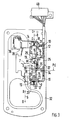
- An automatic transmission for a motor vehicle that can be controlled by an electronic control device can be influenced by a switching device 1: the control device, automatic transmission and motor vehicle are not shown in more detail; for this purpose, reference is made to DE-A 38 07 881 referred to as prior art.
- the switching device 1 comprises a cross-sectionally U-shaped, container-like housing 2 made of plastic, light metal casting or the like, in which a selector lever 3 is mounted on the one hand on a bolt 4 running transversely to the vehicle longitudinal direction B-B and on the other hand on a bolt 5 aligned in the vehicle longitudinal direction B-B.
- the selector lever 3 is also switchable from position D of the first shift gate 6 via a cross gate 7 into a second shift gate 8.
- the first shift gate 6 and the second shift gate 8 run parallel to one another, these forming a double T with the transverse gate 7.
- the selector lever 3 After insertion of the selector lever 3 into the second shift gate 8, the latter can also be pivoted in the vehicle longitudinal direction BB.
- a single pivoting of the selector lever 3 out of a central position M in the plus direction (+) brings about an upshifting by one gear in each case - step-up shifting; downshifting - also by one gear at a time - is carried out by pivoting the lever in the minus direction (-).
- the selector lever 3 is automatically reset to its neutral center position M after each switching operation in the plus or minus direction.
- sensors 9, 10 are controlled by the lever, which are formed by switches 11, 12.
- the switches 11, 12 cooperate with devices 13, 14 which have axially movable pins 15, 16 and springs 17, 18.
- the springs 17, 18 and the pins 15, 16 seek to hold the selector lever 3 in its central position M.
- Both pins 15, 16 are supported directly on the selector lever or a local thickening 19 of the selector lever 3, that is to say are aligned in the longitudinal direction D-D — parallel to the vehicle longitudinal direction B-B.
- the springs 17, 18 designed as helical springs are arranged coaxially to the pins 15, 16.
- the springs 17, 18 are housed in housings 20, 21.
- the spring 17 is supported on a rear wall 22 of the housing 20 and protrudes into a bore 23 in the pin 15 such that the pin 15 is clamped against a further wall 25 of the housing 20 with a stop 24.
- the switches 11, 12 have actuating pins 26, 27 which are adjustable in the direction C-C; the latter extends transversely to the longitudinal direction DD of the shift gate 8 and the pin 15, 16.
- Ramps 28, 29 of the pin 15, 16 are used to adjust the actuating pins 26, 27.
- Each ramp 28 is a cone which extends from the cylindrical pin 15 to expanded to a head 30 which has a conical bevel 31 and cooperates with the thickening 19 of the selector lever 3 to support.
- the switch 11 is actuated via the actuating pin 26 after the position E has been reached.
- a defined pressure point Pd is generated on the selector lever 3, which lies in an optimum force of the spring 17.
- the pressure point Pd can be determined empirically and / or mathematically.
- the switches 11, 12 and the devices 13, 14 are fastened on a support plate 32 with a U-shaped cross section, which can be a sheet metal part and is held in position as a cover on the top of the housing 2 by means of screws 33.
- the switches 11, 12 and the Devices 13, 14 are held on the carrier plate 32 by means of fastening means 34 such as screws, rivets or the like.
- a contact device 35 for the operation of the single gear shift in the second shift gate 8 and a further contact device 36 which reports the non-in-P position, for. B. by acoustic signals, namely when the selector lever 3 is in the first shift gate 6.
- the contact device 35 is provided on the side 37 of the second switching gate 8 facing away from the first switching gate 6, wherein it and its contact lever 38 are oriented perpendicular to the position H of the selector lever 3 which it occupies in the second switching gate 8.
- the further contact device 36 is arranged on the side 39 of the first shift gate 6 facing away from the second shift gate 8, and thus becomes effective when the selector lever 3 is pivoted in the first shift gate 6.
- the switches 11, 12 and the contact devices 35, 36 are components of the same principle that are connected with their cables to a plug 40.
Landscapes
- Engineering & Computer Science (AREA)
- General Engineering & Computer Science (AREA)
- Mechanical Engineering (AREA)
- Chemical & Material Sciences (AREA)
- Combustion & Propulsion (AREA)
- Transportation (AREA)
- Arrangement Or Mounting Of Control Devices For Change-Speed Gearing (AREA)
- Control Of Transmission Device (AREA)
Claims (15)
- Dispositif de changement de vitesse pour une boîte de vitesses automatique, influencée par une commande électronique, d'un véhicule automobile, comportant un levier de sélection dont le pivotement dans une première voie permet de sélectionner différents étages de fonctionnement et des vitesses commutant automatiquement, dans lequel le levier de sélection peut être commuté, à travers une voie transversale, dans une seconde voie parallèle à la première, dans laquelle le levier de sélection, par pivotement unique d'une position centrale de point mort et actionnement d'un premier capteur dans un sens, permet de passer à la vitesse supérieure et, par pivotement unique dans le sens opposé et actionnement d'un second capteur, permet de passer à la vitesse inférieure, de manière qu'après la commutation respective, le levier de sélection soit replacé dans sa position centrale de point mort, caractérisé en ce que les capteurs (9, 10) sont des interrupteurs électriques (11, 12) qui coopèrent avec des dispositifs (13, 14), constitués de tenons (15, 16), soumis à l'action de ressorts (17, 18), tendant à déplacer le levier de sélection (3) dans sa position centrale de point mort (M).
- Dispositif de changement de vitesse selon la revendication 1, caractérisé en ce que les ressorts (17, 18) et les tenons (15, 16) sont orientés dans la direction longitudinales (D-D) de la seconde voie de commutation (8), les tenons (15, 16) étant de préférence directement actionnés par le levier de sélection (3).
- Dispositif de changement de vitesse selon la revendication , caractérisé en ce que les ressorts (17, 18), se présentant sous la forme de ressorts hélicoïdaux, sont coaxiaux aux tenons (15, 16).
- Dispositif de changement de vitesse selon la revendication 3, caractérisé en ce que tous les ressorts (17) et tous les tenons (18) sont logés dans un boîtier (20) commun.
- Dispositif de changement de vitesse selon une ou plusieurs des revendications précédentes, caractérisé en ce que, pour produire un point de pression (Pd) défini du levier de sélection (3), dans la seconde voie de commutation (8), les tenons (15, 16) actionnent les interrupteurs (11, 12) à l'optimum des forces des ressorts (17, 18).
- Dispositif de changement de vitesse selon la revendication 5, caractérisé en ce que les interrupteurs (11, 12) comportent des doigts d'actionnement (26, 27) qui sont disposés transversalement (direction C-C) à la direction longitudinale (B-B) des tenons (15, 16) et sont déplacés par des rampes (28, 29) des tenons (15, 16) mobiles axialement.
- Dispositif de changement de vitesse selon la revendication 6, caractérisé en ce que chaque rampe (28) est un cône qui s'élargit à partir du tenon (15) cylindrique.
- Dispositif de changement de vitesse selon la revendication 7, caractérisé en ce que l'extrémité libre du cône est une tête (30) qui coopère avec le levier de sélection (3).
- Dispositif de changement de vitesse selon une ou plusieurs des revendications précédentes, caractérisé en ce que le dispositif (13, 14) et les interrupteurs (11, 12) sont fixés sur une plaque-support (32) commune.
- Dispositif de commutation selon une ou plusieurs des revendications précédentes, caractérisé en ce que la plaque-support (32) se présente sous la forme d'un couvercle d'un boîtier (2) du dispositif de changement de vitesse (1).
- Dispositif de changement de vitesse selon la revendication 9, caractérisé en ce qu'un dispositif à contact (35) électrique est prévu sur la plaque-support (3), pour la commande manuelle des rapports (voie de commutation 8).
- Dispositif de changement de vitesse selon les revendications 1 et 11, caractérisé en ce que le dispositif à contact (35) est prévu sur le côté (37), opposé à la première voie de commutation (6), de la seconde voie (8).
- Dispositif de changement de vitesse selon une ou plusieurs des revendications précédentes, caractérisé en ce qu'il est prévu sur la plaque-support (32), un autre dispositif à contact (36) pour un signal, de préférence acoustique, signalant la non-position en (P) du levier de sélection (3).
- Dispositif de changement de vitesse selon les revendications 1 et 3, caractérisé en ce que l'autre dispositif à contact (36) est prévu sur le côté (39), opposé à la seconde voie de commutation (8), de la première voie (6).
- Dispositif de changement de vitesse selon une ou plusieurs des revendications précédentes, caractérisé en ce que les interrupteurs (11, 12) et les dispositifs à contact (35, 36) sont des composants reposant sur le même principe.
Applications Claiming Priority (2)
| Application Number | Priority Date | Filing Date | Title |
|---|---|---|---|
| DE3927248A DE3927248C1 (fr) | 1989-08-18 | 1989-08-18 | |
| DE3927248 | 1989-08-18 |
Publications (2)
| Publication Number | Publication Date |
|---|---|
| EP0413115A1 EP0413115A1 (fr) | 1991-02-20 |
| EP0413115B1 true EP0413115B1 (fr) | 1993-01-27 |
Family
ID=6387341
Family Applications (1)
| Application Number | Title | Priority Date | Filing Date |
|---|---|---|---|
| EP90112173A Expired - Lifetime EP0413115B1 (fr) | 1989-08-18 | 1990-06-27 | Dispositif de changement de vitesse |
Country Status (4)
| Country | Link |
|---|---|
| EP (1) | EP0413115B1 (fr) |
| JP (1) | JP3059198B2 (fr) |
| DE (2) | DE3927248C1 (fr) |
| ES (1) | ES2037509T3 (fr) |
Families Citing this family (10)
| Publication number | Priority date | Publication date | Assignee | Title |
|---|---|---|---|---|
| FR2731392B1 (fr) * | 1995-03-06 | 1997-05-30 | Magneti Marelli France | Ensemble de commande a levier, notamment pour boite de vitesses mecanique robotisee |
| DE19549437C2 (de) * | 1995-07-17 | 1999-06-10 | Lemfoerder Metallwaren Ag | Schaltvorrichtung für ein automatisches Getriebe eines Kraftfahrzeugs |
| DE19547750A1 (de) * | 1995-12-20 | 1997-06-26 | Bayerische Motoren Werke Ag | Schalteinrichtung für ein Kraftfahrzeug mit automatischem Getriebe |
| DE19620515C2 (de) * | 1996-05-22 | 1998-04-30 | Lemfoerder Metallwaren Ag | Schaltvorrichtung für ein Automatikgetriebe eines Kraftfahrzeuges |
| DE19633948A1 (de) * | 1996-08-22 | 1998-02-26 | Bayerische Motoren Werke Ag | Wähleinrichtung für ein Automatikgetriebe eines Kraftfahrzeugs |
| DE19637533B4 (de) * | 1996-09-14 | 2007-03-22 | Zf Friedrichshafen Ag | Elektrischer Fahrschalter |
| FR2765941B1 (fr) * | 1997-07-09 | 1999-08-27 | Peugeot | Dispositif de commande manuelle d'une boite de vitesses automatique |
| DE19755096A1 (de) * | 1997-12-11 | 1999-06-17 | Volkswagen Ag | Verfahren und Steuervorrichtung zum Steuern eines Automatikgetriebes oder eines automatisierten Schaltgetriebes eines Kraftfahrzeuges |
| DE19844276C2 (de) * | 1998-09-26 | 2000-11-09 | Porsche Ag | Wähleinrichtung für ein Fahrzeug-Getriebe sowie Schaltermodul hierzu |
| IT201600083331A1 (it) * | 2016-08-08 | 2018-02-08 | Silatech S R L | Dispositivo di comando, particolarmente per cambio di velocità di autoveicolo. |
Family Cites Families (9)
| Publication number | Priority date | Publication date | Assignee | Title |
|---|---|---|---|---|
| GB1158829A (en) * | 1967-08-04 | 1969-07-23 | Ifa Getriebewerke Brandenburg | Shift Mechanism for Overdrive Arrangements |
| US4442730A (en) * | 1981-08-31 | 1984-04-17 | Twin Disc, Incorporated | Vehicle transmission system and a single lever control device therefor |
| GB8307095D0 (en) * | 1983-03-15 | 1983-04-20 | Massey Ferguson Perkins Ltd | Gear selector means |
| JPS60252853A (ja) * | 1984-05-30 | 1985-12-13 | Mitsubishi Motors Corp | 自動変速装置 |
| JPS61157855A (ja) * | 1984-12-27 | 1986-07-17 | Nissan Motor Co Ltd | 自動変速機の手動変速装置 |
| JPS6234214A (ja) * | 1985-08-07 | 1987-02-14 | Hino Motors Ltd | ギア・チエンジ・レバ−・ユニツト |
| JPS63165727U (fr) * | 1987-04-20 | 1988-10-28 | ||
| DE3905769A1 (de) * | 1988-03-01 | 1989-09-14 | Zahnradfabrik Friedrichshafen | Elektrischer fahrschalter |
| DE3807881A1 (de) * | 1988-03-10 | 1989-09-21 | Porsche Ag | Schaltvorrichtung fuer ein automatikgetriebe eines kraftfahrzeugs |
-
1989
- 1989-08-18 DE DE3927248A patent/DE3927248C1/de not_active Expired - Lifetime
-
1990
- 1990-06-27 EP EP90112173A patent/EP0413115B1/fr not_active Expired - Lifetime
- 1990-06-27 ES ES199090112173T patent/ES2037509T3/es not_active Expired - Lifetime
- 1990-06-27 DE DE9090112173T patent/DE59000816D1/de not_active Expired - Lifetime
- 1990-08-15 JP JP2214457A patent/JP3059198B2/ja not_active Expired - Fee Related
Also Published As
| Publication number | Publication date |
|---|---|
| JP3059198B2 (ja) | 2000-07-04 |
| ES2037509T3 (es) | 1993-06-16 |
| JPH0389075A (ja) | 1991-04-15 |
| DE59000816D1 (de) | 1993-03-11 |
| DE3927248C1 (fr) | 1991-02-07 |
| EP0413115A1 (fr) | 1991-02-20 |
Similar Documents
| Publication | Publication Date | Title |
|---|---|---|
| DE4005588C2 (de) | Schaltvorrichtung für ein automatisches Getriebe | |
| DE4426207C1 (de) | Wähleinrichtung für ein Automatikgetriebe eines Kraftfahrzeugs | |
| DE3927922A1 (de) | Schaltvorrichtung fuer ein kraftfahrzeuggetriebe | |
| DE102007010052A1 (de) | Steuer-/Regelvorrichtung für ein Automatikgetriebe | |
| DE19509477B4 (de) | Schaltvorrichtung für ein Geschwindigkeits-Wechselgetriebe | |
| EP0413115B1 (fr) | Dispositif de changement de vitesse | |
| DE19620515C2 (de) | Schaltvorrichtung für ein Automatikgetriebe eines Kraftfahrzeuges | |
| EP0699853B1 (fr) | Tringlerie de sélection des vitesses pour boîte de vitesse d'un véhicule | |
| EP0350497A1 (fr) | Console de changement de vitesses. | |
| DE102010007507A1 (de) | Verfahren zum Blockieren mindestens einer Anwahlposition eines Wählelements sowie Schalteinrichtung für Fahrzeuge | |
| DE10315643B3 (de) | Shift by wire-Schaltung mit P-Position | |
| EP0825364A2 (fr) | Dispositif de sélection pour boíte de vitesses automatique de véhicule automobile | |
| DE19849076A1 (de) | Wähleinrichtung für ein automatisch geschaltetes Getriebe eines Kraftfahrzeugs | |
| EP0121167A1 (fr) | Mécanisme pour le contrôle semi-automatique ou automatique de boîte de vitesses | |
| EP1081414B1 (fr) | Dispositif de changement de vitesses pour commander une transmission automatique de véhicule automobile | |
| DE19924238A1 (de) | Schaltvorrichtung für ein Automatikgetriebe eines Kraftfahrzeuges | |
| DE3842818C1 (en) | Selector device for a motor-vehicle gearbox | |
| DE10040077C2 (de) | Aktuator zur Betätigung einer mit einem Hydraulik-Wählschieber gekoppelten Parksperreneinrichtung | |
| DE19850374A1 (de) | Kraftfahrzeug mit einer Wähleinrichtung für ein automatisch geschaltetes Getriebe | |
| WO1985001254A1 (fr) | Dispositif de changement de vitesse pour boite de vitesses manuelle de vehicules a moteur | |
| DE102005021862A1 (de) | Anordnung des Wählschiebers und des hydraulischen Steuergerätes in einem stufenlos verstellbaren Automatgetriebe, insbesondere einem Umschlingungsgetriebe | |
| DE10213724A1 (de) | Vorrichtung zur Steuerung des Schaltens von Gangstufen in einem Getriebe | |
| DE10358510B3 (de) | Schaltvorrichtung für ein Schaltgetriebe eines Kraftfahrzeugs | |
| EP1965099B1 (fr) | Dispositif de changement de vitesses avec élément ressort de rappel d'organes de sélection pour transmission multivitesses | |
| DE10019773C1 (de) | Wählvorrichtung für Kraftfahrzeuggetriebe |
Legal Events
| Date | Code | Title | Description |
|---|---|---|---|
| PUAI | Public reference made under article 153(3) epc to a published international application that has entered the european phase |
Free format text: ORIGINAL CODE: 0009012 |
|
| AK | Designated contracting states |
Kind code of ref document: A1 Designated state(s): DE ES FR GB IT NL SE |
|
| 17P | Request for examination filed |
Effective date: 19910628 |
|
| 17Q | First examination report despatched |
Effective date: 19920624 |
|
| ITF | It: translation for a ep patent filed |
Owner name: DE DOMINICIS & MAYER S. |
|
| GRAA | (expected) grant |
Free format text: ORIGINAL CODE: 0009210 |
|
| AK | Designated contracting states |
Kind code of ref document: B1 Designated state(s): DE ES FR GB IT NL SE |
|
| GBT | Gb: translation of ep patent filed (gb section 77(6)(a)/1977) |
Effective date: 19930209 |
|
| REF | Corresponds to: |
Ref document number: 59000816 Country of ref document: DE Date of ref document: 19930311 |
|
| ET | Fr: translation filed | ||
| REG | Reference to a national code |
Ref country code: ES Ref legal event code: FG2A Ref document number: 2037509 Country of ref document: ES Kind code of ref document: T3 |
|
| PLBE | No opposition filed within time limit |
Free format text: ORIGINAL CODE: 0009261 |
|
| STAA | Information on the status of an ep patent application or granted ep patent |
Free format text: STATUS: NO OPPOSITION FILED WITHIN TIME LIMIT |
|
| 26N | No opposition filed | ||
| EAL | Se: european patent in force in sweden |
Ref document number: 90112173.1 |
|
| PGFP | Annual fee paid to national office [announced via postgrant information from national office to epo] |
Ref country code: NL Payment date: 20000630 Year of fee payment: 11 |
|
| PG25 | Lapsed in a contracting state [announced via postgrant information from national office to epo] |
Ref country code: NL Free format text: LAPSE BECAUSE OF NON-PAYMENT OF DUE FEES Effective date: 20020101 |
|
| REG | Reference to a national code |
Ref country code: GB Ref legal event code: IF02 |
|
| NLV4 | Nl: lapsed or anulled due to non-payment of the annual fee |
Effective date: 20020101 |
|
| REG | Reference to a national code |
Ref country code: FR Ref legal event code: TP |
|
| PGFP | Annual fee paid to national office [announced via postgrant information from national office to epo] |
Ref country code: ES Payment date: 20090623 Year of fee payment: 20 |
|
| PGFP | Annual fee paid to national office [announced via postgrant information from national office to epo] |
Ref country code: SE Payment date: 20090612 Year of fee payment: 20 Ref country code: IT Payment date: 20090625 Year of fee payment: 20 Ref country code: FR Payment date: 20090615 Year of fee payment: 20 |
|
| REG | Reference to a national code |
Ref country code: FR Ref legal event code: CD |
|
| PGFP | Annual fee paid to national office [announced via postgrant information from national office to epo] |
Ref country code: GB Payment date: 20090618 Year of fee payment: 20 Ref country code: DE Payment date: 20090602 Year of fee payment: 20 |
|
| REG | Reference to a national code |
Ref country code: GB Ref legal event code: PE20 Expiry date: 20100626 |
|
| EUG | Se: european patent has lapsed | ||
| REG | Reference to a national code |
Ref country code: ES Ref legal event code: FD2A Effective date: 20100628 |
|
| PG25 | Lapsed in a contracting state [announced via postgrant information from national office to epo] |
Ref country code: ES Free format text: LAPSE BECAUSE OF EXPIRATION OF PROTECTION Effective date: 20100628 |
|
| PG25 | Lapsed in a contracting state [announced via postgrant information from national office to epo] |
Ref country code: GB Free format text: LAPSE BECAUSE OF EXPIRATION OF PROTECTION Effective date: 20100626 |
|
| PG25 | Lapsed in a contracting state [announced via postgrant information from national office to epo] |
Ref country code: DE Free format text: LAPSE BECAUSE OF EXPIRATION OF PROTECTION Effective date: 20100627 |