EP0412303B1 - Vorrichtung zum Schutz von auf dem Boden verlegten Installationsleitungen - Google Patents
Vorrichtung zum Schutz von auf dem Boden verlegten Installationsleitungen Download PDFInfo
- Publication number
- EP0412303B1 EP0412303B1 EP90113184A EP90113184A EP0412303B1 EP 0412303 B1 EP0412303 B1 EP 0412303B1 EP 90113184 A EP90113184 A EP 90113184A EP 90113184 A EP90113184 A EP 90113184A EP 0412303 B1 EP0412303 B1 EP 0412303B1
- Authority
- EP
- European Patent Office
- Prior art keywords
- support
- parallel
- free edge
- trough
- web
- Prior art date
- Legal status (The legal status is an assumption and is not a legal conclusion. Google has not performed a legal analysis and makes no representation as to the accuracy of the status listed.)
- Expired - Lifetime
Links
- 238000009434 installation Methods 0.000 description 14
- 208000000260 Warts Diseases 0.000 description 1
- 239000002826 coolant Substances 0.000 description 1
- 239000000463 material Substances 0.000 description 1
- 230000000149 penetrating effect Effects 0.000 description 1
- 201000010153 skin papilloma Diseases 0.000 description 1
- 239000011343 solid material Substances 0.000 description 1
Images
Classifications
-
- F—MECHANICAL ENGINEERING; LIGHTING; HEATING; WEAPONS; BLASTING
- F16—ENGINEERING ELEMENTS AND UNITS; GENERAL MEASURES FOR PRODUCING AND MAINTAINING EFFECTIVE FUNCTIONING OF MACHINES OR INSTALLATIONS; THERMAL INSULATION IN GENERAL
- F16L—PIPES; JOINTS OR FITTINGS FOR PIPES; SUPPORTS FOR PIPES, CABLES OR PROTECTIVE TUBING; MEANS FOR THERMAL INSULATION IN GENERAL
- F16L57/00—Protection of pipes or objects of similar shape against external or internal damage or wear
-
- H—ELECTRICITY
- H02—GENERATION; CONVERSION OR DISTRIBUTION OF ELECTRIC POWER
- H02G—INSTALLATION OF ELECTRIC CABLES OR LINES, OR OF COMBINED OPTICAL AND ELECTRIC CABLES OR LINES
- H02G3/00—Installations of electric cables or lines or protective tubing therefor in or on buildings, equivalent structures or vehicles
- H02G3/02—Details
- H02G3/04—Protective tubing or conduits, e.g. cable ladders or cable troughs
- H02G3/0437—Channels
Definitions
- the invention relates to a device for protecting installation lines laid on the floor, consisting of a ramp that can be driven over.
- installation lines such as hoses (hydraulics, coolant, air and the like) laid on the floor in machine halls or the like, or also to protect pipelines or electrical lines by drivable ramps or the like, so that this is avoided Operators fall across these installation lines and in particular ensure that industrial trucks, such as forklifts, can run over these installation lines without damaging them.
- a device according to the OB of claim 1 is known from document GB-A-2 120 464. It consists of solid material, has a trapezoidal cross section and at least one channel for the cables to be protected.
- the invention has for its object to provide an extremely simple structure that can be easily installed and provides complete protection for installed installation lines or the like.
- the invention proposes that the ramp is formed from channel profiles, each channel profile having a standing ridge perpendicular in the position of use, a surface projecting at right angles from this and an inclined surface adjoining it, the free edge of which in that of the standing edge level of the riot bridge ends.
- This configuration makes it possible, for example, to secure installations installed on the floor near a wall by the ramp, in that the ramp is applied to the wall surface with its ridge and points away from the wall with its inclined surface. Such an installation is also useful, for example, when arranging installations near a machine frame or the like.
- two channel profiles are joined to one another with contact ridges which are oriented parallel to one another and are arranged next to one another.
- This design and arrangement makes it possible to protect free installation lines laid on the floor and to form drive-over aids, with the chosen spatial shape and relatively small thickness of the material forming the channel profiles generating sufficient supporting forces which prevent deformation of the channel profile when the channel is driven over .
- the standing ridge is suitable and intended to take on high forces without the channel profile being deformed.
- the subsequent laying of such gutter profiles is also very easy, by using the gutter profiles with the ridges either overlapping the installation lines laid on the floor or partially overlapping them in the spaces between parallel installed installation lines.
- the channel profiles have a surface running parallel to the contact plane at the free edge of the inclined surface.
- This arrangement ensures that, for example, a wheeled vehicle, which wants to drive over the channel profiles, first drives with a wheel or the wheels of an axle onto the surface running parallel to the contact plane, thereby securing the channel profile to a certain extent on the contact area, and only then the vehicle continues to drive and loads the channel profile. In spite of the loose installation on the sub-floor, this ensures that the position is as far as possible when in use.
- the free edge of the parallel surface is angled in the manner of a chamfer, the free edge of the chamfer ending in the contact plane and the parallel surface being set back at least by the wall thickness of the channel profile.
- This arrangement makes it possible to achieve a telescopic extension of the larger channel profile through the somewhat smaller channel profile, whereby a further attachment field can be generated by further attaching a larger channel profile to the telescopically displaceable smaller channel profile.
- abutting contact webs can be connected by means of U-shaped connectors which encompass the free edge of the web edge.
- the connectors can be connected to the support webs by means of screws or similar fastening means, the fastening means reaching through the webs and the legs of the connectors.
- channel profiles are formed from wart plates. This improves the surface in terms of increasing friction.
- the device for protecting installation cables laid on the floor consists of a ramp which can be driven over and which is formed from channel profiles 1, 1 '.
- Each channel profile 1.1 ' has a vertical ridge 2, 2' in the position of use.
- a surface projecting at a right angle from this 3.3 ' is formed, which merges into an inclined surface 4.4', the free edge of which may end in the plane spanned by the edge of the support ridge 2.2 '.
- two channel profiles 1 and 1 'with parallel to each other and arranged ridges 2 and 2' are joined together, so that a drive-over ramp is formed.
- the channel profiles 1, 1 'on the edge of the inclined surface then have a surface 5.5' running parallel to the contact plane.
- the free edge of the parallel surface 5 is angled in the manner of a chamfer 6, the free edge of the chamfer 6 ending in the contact plane and the parallel surface being set back at least by the wall thickness of the channel profile 1.
- a further shape-like channel profile 1 ' is telescopically inserted into the end face of the channel profile 1, the length of its support web 2' being shortened by at least the wall thickness of the outer channel profile 1 compared to its support web length.
- the edge of the surface parallel to the contact plane 5 ' is in the area in which the profile 1' is overlapped by the profile 1, from the chamfer 6 provided with the parallel surface 5 of the outer channel profile 1, the edge of the chamfer 6 and the surface 5 'rest on the sub-floor.
- the support ridges 2 and 2 'of mirror-symmetrically laid channel profiles 1.1' can be connected to each other by means of U-shaped connectors 7 which encompass the free edge of the support ridges 2 'and 2.
- the attachment can be carried out by penetrating screws or other similar fasteners.
- the invention is not limited to the exemplary embodiment, but is variable in many ways within the scope of the disclosure.
Landscapes
- Engineering & Computer Science (AREA)
- General Engineering & Computer Science (AREA)
- Mechanical Engineering (AREA)
- Architecture (AREA)
- Civil Engineering (AREA)
- Structural Engineering (AREA)
- Floor Finish (AREA)
- Tents Or Canopies (AREA)
Description
- Die Erfindung betrifft eine Vorrichtung zum Schutz von auf dem Boden verlegten Installationsleitungen, bestehend aus einer überfahrbaren Rampe.
- In der betrieblichen Praxis besteht ein erhebliches Bedürfnis dafür, bodenseitig in Maschinenhallen oder dergleichen verlegte Installationsleitungen, wie Schläuche (Hydraulik, Kühlflüssigkeit, Luft und dergleichen) oder auch Rohrleitungen oder elektrische Leitungen durch überfahrbare Rampen oder dergleichen zu schützen, so daß vermieden ist, daß das Bedienungspersonal über diese Installationsleitungen stolpert und insbesondere dafür gesorgt ist, daß Flurfördergeräte, wie beispielsweise Gabelstapler, diese Installationsleitungen ohne Beschädigung derselben überfahren können.
- Im Stand der Technik ist hierzu beispielsweise bekannt, daß beidseitig neben den Installationsleitungen Holzbohlen ausreichender Dicke verlegt werden, die einen gewissen Schutz und eine Überfahrhilfe bilden. Eine Vorrichtung gemäß dem O.B. des Anspruchs 1 ist aus dem Dokument GB-A-2 120 464 bekannt.
Sie besteht aus Vollmaterial, weist einen trapezförmigen Querschnitt und wenigstens einen Kanal für die zu schützenden Kabel auf. - Ausgehend von diesem Stand der Technik liegt der Erfindung die Aufgabe zugrunde, eine äußerst einfach aufgebaute Vorrichtung zu schaffen, die einfach verlegt werden kann und einen vollständigen Schutz für verlegte Installationsleitungen oder dergleichen bildet.
- Zur Lösung dieser Aufgabe schlägt die Erfindung vor, daß die Rampe aus Rinnenprofilen gebildet ist, wobei jedes Rinnenprofil einen in der Gebrauchslage lotrechten Aufstandssteg, eine oberseitig rechtwinklig von diesem abragende Fläche und eine an diese anschließende Schrägfläche aufweist, deren freie Randkante in der von der Aufstandsrandkante des Aufstandssteges aufgespannten Ebene endet.
- Durch diese Ausbildung ist es möglich, beispielsweise nahe einer Wand auf dem Boden verlegte Installationen durch die Rampe zu sichern, indem die Rampe mit ihrem Aufstandssteg an die Wandfläche angelegt und mit ihrer Schrägfläche von der Wand wegweist. Eine derartige Installation ist beispielsweise auch bei der Anordnung von Installationen nahe eines Maschinengestells oder dergleichen nützlich.
- Bevorzugt ist aber vorgesehen, daß zwei Rinnenprofile mit parallel zueinander gerichteten und aneinander angeordneten Aufstandsstegen aneinandergefügt sind.
- Durch diese Ausbildung und Anordnung ist es möglich, freie auf dem Boden verlegte Installationsleitungen zu schützen und Überfahrhilfen zu bilden, wobei durch die gewählte Raumform bei relativ geringer Dicke des die Rinnenprofile bildenden Materials ausreichende Stützkräfte erzeugt werden, die eine Deformation des Rinnenprofils beim Überfahren desselben unterbinden.
- Insbesondere der lotrecht stehende Aufstandssteg ist geeignet und dazu bestimmt, hohe Kräfte zu übernehmen, ohne daß eine Deformation des Rinnenprofils erfolgen kann.
Auch das nachträgliche Verlegen derartiger Rinnenprofile ist sehr einfach möglich, indem die Rinnenprofile mit den Aufstandsstegen entweder die auf den Boden verlegten Installationsleitungen übergreifend oder diese teilweise übergreifend in die Zwischenräume zwischen parallel verlegten Installationsleitungen eingreifend eingesetzt werden. - Besonders bevorzugt ist vorgesehen, daß die Rinnenprofile an die freie Randkante der Schrägfläche anschließend eine parallel zur Aufstandsebene verlaufende Fläche aufweisen.
- Durch diese Anordnung ist sichergestellt, daß beispielsweise ein Radfahrzeug, welches die Rinnenprofile überfahren will, zunächst mit einem Rad oder den Rädern einer Achse auf die parallel zur Aufstandsebene verlaufende Fläche auffährt, wobei hierdurch eine gewisse Lagesicherung des Rinnenprofils an der Aufstandsfläche erfolgt, und dann erst das Fahrzeug weiterfährt und dabei das Rinnenprofil belastet. Trotz der losen Installation auf dem Unterboden ist damit eine weitest gehende Lagesicherheit bei der Benutzung gewährleistet.
- Bevorzugt ist ferner vorgesehen, daß die freie Randkante der parallel verlaufenden Fläche nach Art einer Anphasung abgewinkelt ist, wobei die freie Randkante der Anphasung in der Aufstandsebene endet und die parallel verlaufende Fläche mindestens um die Wandstärke des Rinnenprofiles zurückversetzt ist.
- Eine in Kombination damit besonders vorteilhafte Weiterbildung wird darin gesehen, daß in die Stirnseiten der Rinnenprofile weitere formähnliche Rinnenprofile teleskopartig einschiebbar sind, deren Aufstandssteglänge mindestens um die Wandstärke des äußeren Rinnenprofils gegenüber dessen Aufstandssteglänge verkürzt ist und dessen parallel zur Aufstandsebene verlaufende Fläche von der mit der Anphasung versehenen parallelen Fläche des äußeren Rinnenprofils übergriffen ist.
- Durch diese Anordnung ist es möglich, durch das formähnliche etwas kleinere Rinnenprofil eine teleskopartige Verlängerung des größeren Rinnenprofils zu erreichen, wobei durch weiteren Ansatz eines größeren Rinnenprofils auf das teleskopartig verschiebbare kleinere Rinnenprofil ein weiteres Anbaufeld erzeugt werden kann.
- Weiterhin kann bevorzugt sein, daß die aneinander anliegenden Aufstandsstege mittels U-förmiger Verbinder verbindbar sind, die die freie Stegrandkante umgreifen.
- Dabei kann vorzugsweise vorgesehen sein, daß die Verbinder mittels Schrauben oder dergleichen Befestigungsmitteln mit den Aufstandsstegen verbindbar sind, wobei die Befestigungsmittel die Stege und die Schenkel der Verbinder durchgreifen.
- Auch kann bevorzugt sein, daß die Rinnenprofile aus Warzenblechen geformt sind. Hierdurch wird die Oberfläche im Sinne einer Reibungserhöhung verbessert.
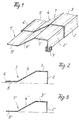
- Ein Ausführungsbeispiel der Erfindung ist in der Zeichnung dargestellt und im folgenden näher beschrieben.
- Es zeigt:
- Fig. 1 eine erfindungsgemäße Vorrichtung in Ansicht,
- Fig. 2 eine Einzelheit im Schnitt gesehen;
- Fig. 3 eine weitere Einzelheit ebenfalls im Schnitt gesehen.
- Die Vorrichtung zum Schutz von auf dem Boden verlegten Installationsleitungen besteht aus einer überfahrbaren Rampe, die aus Rinnenprofilen 1, 1′gebildet ist. Jedes Rinnenprofil 1,1′ weist einen in der Gebrauchslage lotrechten Aufstandssteg 2, 2′ auf. An dessen in der Gebrauchslage oberen Rand ist eine rechtwinklig von diesem abragende Fläche 3,3 ′ angeformt, die in eine Schrägfläche 4,4′ übergeht, deren freie Randkante in der von der Aufstandsrandkante des Aufstandssteges 2,2′ aufgespannten Ebene enden kann. Dabei ist selbstverständlich möglich und vorzugsweise vorgesehen, daß jeweils zwei Rinnenprofile 1 bzw. 1′ mit parallel zueinander gerichteten und aneinander angeordneten Aufstandsstegen 2 bzw. 2′ aneinandergefügt sind, so daß eine überfahrbare Rampe gebildet ist. Im Ausführungsbeispiel weisen die Rinnenprofile 1, 1′ an die Randkante der Schrägfläche anschließend eine parallel zur Aufstandsebene verlaufende Fläche 5,5′ auf. Bei dem Rinnenprofil 1 ist die freie Randkante der parallel verlaufenden Fläche 5 nach Art einer Anphasung 6 abgewinkelt, wobei die freie Randkante der Anphasung 6 in der Aufstandsebene endet und die parallel verlaufende Fläche mindestens um die Wandstärke des Rinnenprofiles 1 zurückversetzt ist.
- Wie insbesondere aus Figur 1 ersichtlich, ist in die Stirnseite des Rinnenprofiles 1 ein weiteres formähnliches Rinnenprofil 1′ teleskopartig eingeschoben, wobei die Länge von dessen Aufstandssteg 2′ mindestens um die Wandstärke des äußeren Rinnenprofils 1 gegenüber dessen Aufstandsteglänge verkürzt ist. Die Randkante der parallel zur Aufstandsebene verlaufenden Fläche 5′ ist im Bereich, in welchem das Profil 1′ von dem Profil 1 übergriffen ist, von der mit der Anphasung 6 versehenen parallelen Fläche 5 des äußeren Rinnenprofils 1 vollständig übergriffen, wobei die Randkante der Anphasung 6 und die Fläche 5′ auf dem Unterboden aufliegen.
- Die Aufstandsstege 2 bzw. 2′ von spiegelsymmetrisch zueinander verlegten Rinnenprofilen 1,1′ sind mittels U-förmiger Verbinder 7 miteinander verbindbar, die die freie Randkante der Aufstandsstege 2′ bzw. 2 umgreifen. Die Befestigung kann mittels durchgreifender Schrauben oder anderer ähnlicher Befestigungsmittel erfolgen.
Die Erfindung ist nicht auf das Ausführungsbeispiel beschränkt, sondern im Rahmen der Offenbarung vielfach variabel.
Claims (8)
- Vorrichtung zum Schutz von auf dem Boden verlegten Installationsleitungen, bestehend aus einer überfahrbaren Rampe, dadurch gekennzeichnet, daß die Rampe aus Rinnenprofilen (1,1′) gebildet ist, wobei jedes Rinnenprofil (1,1′) einen in der Gebrauchslage lotrechten Aufstandssteg (2,2′), eine oberseitig rechtwinklig von diesem abragende Fläche (3,3′) und eine an diese anschließende Schrägfläche (4,4′) aufweist, deren freie Randkante in der von der Aufstandsrandkante des Aufstandssteges (2,2′) aufgespannten Ebene endet.
- Vorrichtung nach Anspruch 1, dadurch gekennzeichnet, daß zwei Rinnenprofile (1 bzw. 1′) mit parallel zueinander gerichteten und aneinander angeordneten Aufstandsstegen (2 bzw. 2′) aneinandergefügt sind.
- Vorrichtung nach Anspruch 1 oder 2, dadurch gekennzeichnet, daß die Rinnenprofile (1,1′) an die freie Randkante der Schrägfläche (4,4′) anschließend eine parallell zur Aufstandsebene verlaufende Fläche (5,5′) aufweisen.
- Vorrichtung nach einem der Ansprüche 1 bis 3, dadurch gekennzeichnet, daß die freie Randkante der parallel verlaufenden Fläche (5) nach Art einer Anphasung (6) abgewinkelt ist, wobei die freie Randkante der Anphasung (6) in der Aufstandsebene endet und die parallel verlaufende Fläche (5) mindestens um die Wandstärke des Rinnenprofils (1) zurückversetzt ist.
- Vorrichtung nach einem der Ansprüche 1 bis 4, dadurch gekennzeichnet, daß in die Stirnseiten der Rinnenprofile (1′) weitere formähnliche Rinnenprofile (1′) teleskopartig einschiebbar sind, deren Aufstandssteglänge mindestens um die Wandstärke des äußeren Rinnenprofils (1) gegenüber dessen Aufstandssteglänge verkürzt ist und dessen parallel zur Aufstandsebene verlaufende Fläche (5′) von der mit der Anphasung (6) versehenen parallelen Fläche (5) des äußeren Rinnenprofils (1) übergriffen ist.
- Vorrichtung nach einem der Ansprüche 1 bis 5, dadurch gekennzeichnet, daß die aneinander anliegenden Aufstandsstege (2 bzw. 2′) mittels U-förmiger Verbinder (7) verbindbar sind, die die freie Stegrandkante umgreifen.
- Vorrichtung nach Anspruch 6, dadurch gekennzeichnet, daß die Verbinder (7) mittels Schrauben oder dergleichen Befestigungsmitteln mit den Aufstandsstegen (2,2′) verbindbar sind, wobei die Befestigungsmittel die Stege und die Schenkel der Verbinder durchgreifen.
- Vorrichtung nach einem der Ansprüche 1 bis 7, dadurch gekennzeichnet, daß die Rinnenprofile (1,1′) aus Warzenblechen geformt sind.
Applications Claiming Priority (2)
| Application Number | Priority Date | Filing Date | Title |
|---|---|---|---|
| DE8909520U | 1989-08-08 | ||
| DE8909520U DE8909520U1 (de) | 1989-08-08 | 1989-08-08 | Vorrichtung zum Schutz von auf dem Boden verlegten Installationsleitungen |
Publications (3)
| Publication Number | Publication Date |
|---|---|
| EP0412303A2 EP0412303A2 (de) | 1991-02-13 |
| EP0412303A3 EP0412303A3 (en) | 1991-12-18 |
| EP0412303B1 true EP0412303B1 (de) | 1994-08-31 |
Family
ID=6841781
Family Applications (1)
| Application Number | Title | Priority Date | Filing Date |
|---|---|---|---|
| EP90113184A Expired - Lifetime EP0412303B1 (de) | 1989-08-08 | 1990-07-11 | Vorrichtung zum Schutz von auf dem Boden verlegten Installationsleitungen |
Country Status (2)
| Country | Link |
|---|---|
| EP (1) | EP0412303B1 (de) |
| DE (2) | DE8909520U1 (de) |
Families Citing this family (4)
| Publication number | Priority date | Publication date | Assignee | Title |
|---|---|---|---|---|
| DE8913040U1 (de) * | 1989-11-04 | 1989-12-21 | Wolff, Ferdinand, 6750 Kaiserslautern | Vorrichtung zum Schutz von Kabeln, Leitungen o.dgl. |
| GB9120194D0 (en) * | 1991-09-21 | 1991-11-06 | Transmission And Lighting Ltd | Cable trunking |
| CN103482425A (zh) * | 2013-09-27 | 2014-01-01 | 苏州晓炎自动化设备有限公司 | 一种线槽 |
| CN109045535B (zh) * | 2018-09-28 | 2020-10-16 | 谢钊锋 | 一种基于高效率水管防护的远距离接水的消防车 |
Family Cites Families (5)
| Publication number | Priority date | Publication date | Assignee | Title |
|---|---|---|---|---|
| DE1757663U (de) * | 1957-10-19 | 1957-12-12 | Prakla Gmbh | Schutzvorrichtung fuer provisorisch auf dem boden verlegte kabel u. dgl. |
| DE2220745A1 (de) * | 1972-04-27 | 1973-11-08 | Polynorm Kunststoff Gmbh | Kabelabdeckelement aus kunststoff |
| BE793882A (fr) * | 1973-01-11 | 1973-07-11 | Acec | Cable ou tuyauterie fixe le long d'une paroi ou d'un mur |
| US4242010A (en) * | 1977-08-19 | 1980-12-30 | Ingenior F. Selmer AS | Method and means for protecting a sea bottom surface and an installation on same |
| GB2120464B (en) * | 1982-05-19 | 1986-01-02 | Lux Traffic Controls Ltd | Cable duct |
-
1989
- 1989-08-08 DE DE8909520U patent/DE8909520U1/de not_active Expired
-
1990
- 1990-07-11 DE DE59006961T patent/DE59006961D1/de not_active Expired - Fee Related
- 1990-07-11 EP EP90113184A patent/EP0412303B1/de not_active Expired - Lifetime
Also Published As
| Publication number | Publication date |
|---|---|
| DE8909520U1 (de) | 1989-10-05 |
| DE59006961D1 (de) | 1994-10-06 |
| EP0412303A2 (de) | 1991-02-13 |
| EP0412303A3 (en) | 1991-12-18 |
Similar Documents
| Publication | Publication Date | Title |
|---|---|---|
| EP1366550B1 (de) | Kabelbrücke | |
| EP1010836A2 (de) | Vorrichtung zur Ausbildung des Übergangs zwischen zwei aneinandergrenzenden Bodenabschnitten unterschiedlicher Höhe | |
| EP0443441B1 (de) | Gitterzaun | |
| DD237529A5 (de) | Plattenfoermiges bauelement und baukonstruktion mit derartigen bauelementen | |
| DE2803892A1 (de) | Bodenbelagsplatte und damit hergestellter bodenbelag | |
| DE202009010705U1 (de) | Wandsegment und Hochbeet bestehend aus Wandsegmenten | |
| DE102008006251B4 (de) | Verbindungselement für einen Bodenbelag | |
| EP0647747B1 (de) | Tragwerk für die Bedachung und/oder Aussenhaut-Beplankung von Gebäuden | |
| EP0412303A2 (de) | Vorrichtung zum Schutz von auf dem Boden verlegten Installationsleitungen | |
| EP1197611A1 (de) | Fussboden-Fertigplatte zur Bildung eines demontierbaren Fussbodens | |
| DE60009330T2 (de) | Vorrichtung und verfahren zur befestigung eines flachelements an einem fahrzeug | |
| DE3720025C2 (de) | ||
| EP0960985A2 (de) | I-förmiger Träger für Gebäudekonstruktionen | |
| EP1022389A2 (de) | Schalungselement für Industriefussböden | |
| AT394416B (de) | Eckverbinder fuer zargen u.dgl. | |
| EP1183972B1 (de) | Profilschienensystem für Bodenbeläge | |
| DE10010372B4 (de) | Niveauausgleichssystem für geparkte Fahrzeuge | |
| DE19640128A1 (de) | Bodenbelag-Element | |
| EP1950349B1 (de) | Bodenbelag | |
| DE9011341U1 (de) | Vorrichtung zum Schutz von auf dem Boden verlegten Installationsleitungen | |
| EP1067070B1 (de) | Auffahrschiene | |
| DE19503429B4 (de) | Vorrichtung für das stirnseitige Verbinden von Kabelbahnen | |
| DE4200691A1 (de) | Versorgungseinheit | |
| EP3299519B1 (de) | Brückenelement einer verlegbaren brücke und bodenkontaktelement für ein brückenelement | |
| EP1128001A2 (de) | Vorrichtung zur Ausbildung von Bewegungsfugen zwischen auf einem Rohboden verlegten Bodenbelagsfeldern |
Legal Events
| Date | Code | Title | Description |
|---|---|---|---|
| PUAI | Public reference made under article 153(3) epc to a published international application that has entered the european phase |
Free format text: ORIGINAL CODE: 0009012 |
|
| AK | Designated contracting states |
Kind code of ref document: A2 Designated state(s): BE CH DE ES FR GB IT LI LU NL SE |
|
| PUAL | Search report despatched |
Free format text: ORIGINAL CODE: 0009013 |
|
| AK | Designated contracting states |
Kind code of ref document: A3 Designated state(s): BE CH DE ES FR GB IT LI LU NL SE |
|
| 17P | Request for examination filed |
Effective date: 19920128 |
|
| 17Q | First examination report despatched |
Effective date: 19931214 |
|
| GRAA | (expected) grant |
Free format text: ORIGINAL CODE: 0009210 |
|
| AK | Designated contracting states |
Kind code of ref document: B1 Designated state(s): BE CH DE ES FR GB IT LI LU NL SE |
|
| PG25 | Lapsed in a contracting state [announced via postgrant information from national office to epo] |
Ref country code: NL Effective date: 19940831 Ref country code: IT Free format text: LAPSE BECAUSE OF FAILURE TO SUBMIT A TRANSLATION OF THE DESCRIPTION OR TO PAY THE FEE WITHIN THE PRESCRIBED TIME-LIMIT;WARNING: LAPSES OF ITALIAN PATENTS WITH EFFECTIVE DATE BEFORE 2007 MAY HAVE OCCURRED AT ANY TIME BEFORE 2007. THE CORRECT EFFECTIVE DATE MAY BE DIFFERENT FROM THE ONE RECORDED. Effective date: 19940831 Ref country code: ES Free format text: THE PATENT HAS BEEN ANNULLED BY A DECISION OF A NATIONAL AUTHORITY Effective date: 19940831 Ref country code: BE Effective date: 19940831 Ref country code: FR Effective date: 19940831 |
|
| REF | Corresponds to: |
Ref document number: 59006961 Country of ref document: DE Date of ref document: 19941006 |
|
| GBT | Gb: translation of ep patent filed (gb section 77(6)(a)/1977) |
Effective date: 19940909 |
|
| PG25 | Lapsed in a contracting state [announced via postgrant information from national office to epo] |
Ref country code: SE Effective date: 19941130 |
|
| EN | Fr: translation not filed | ||
| NLV1 | Nl: lapsed or annulled due to failure to fulfill the requirements of art. 29p and 29m of the patents act | ||
| PLBE | No opposition filed within time limit |
Free format text: ORIGINAL CODE: 0009261 |
|
| STAA | Information on the status of an ep patent application or granted ep patent |
Free format text: STATUS: NO OPPOSITION FILED WITHIN TIME LIMIT |
|
| PG25 | Lapsed in a contracting state [announced via postgrant information from national office to epo] |
Ref country code: GB Effective date: 19950711 |
|
| PG25 | Lapsed in a contracting state [announced via postgrant information from national office to epo] |
Ref country code: LI Effective date: 19950731 Ref country code: CH Effective date: 19950731 Ref country code: LU Free format text: LAPSE BECAUSE OF NON-PAYMENT OF DUE FEES Effective date: 19950731 |
|
| 26N | No opposition filed | ||
| GBPC | Gb: european patent ceased through non-payment of renewal fee |
Effective date: 19950711 |
|
| REG | Reference to a national code |
Ref country code: CH Ref legal event code: PL |
|
| PG25 | Lapsed in a contracting state [announced via postgrant information from national office to epo] |
Ref country code: DE Effective date: 19960402 |