EP0410377A2 - Verstellbare Schulterverankerung - Google Patents
Verstellbare Schulterverankerung Download PDFInfo
- Publication number
- EP0410377A2 EP0410377A2 EP90114155A EP90114155A EP0410377A2 EP 0410377 A2 EP0410377 A2 EP 0410377A2 EP 90114155 A EP90114155 A EP 90114155A EP 90114155 A EP90114155 A EP 90114155A EP 0410377 A2 EP0410377 A2 EP 0410377A2
- Authority
- EP
- European Patent Office
- Prior art keywords
- slide
- stopper
- anchor
- shoe
- base
- Prior art date
- Legal status (The legal status is an assumption and is not a legal conclusion. Google has not performed a legal analysis and makes no representation as to the accuracy of the status listed.)
- Granted
Links
Images


Classifications
-
- B—PERFORMING OPERATIONS; TRANSPORTING
- B60—VEHICLES IN GENERAL
- B60R—VEHICLES, VEHICLE FITTINGS, OR VEHICLE PARTS, NOT OTHERWISE PROVIDED FOR
- B60R22/00—Safety belts or body harnesses in vehicles
- B60R22/18—Anchoring devices
- B60R22/20—Anchoring devices adjustable in position, e.g. in height
- B60R22/201—Anchoring devices adjustable in position, e.g. in height with the belt anchor connected to a slider movable in a vehicle-mounted track
- B60R22/202—Anchoring devices adjustable in position, e.g. in height with the belt anchor connected to a slider movable in a vehicle-mounted track the slider comprising spring-actuated locking means
- B60R22/203—Anchoring devices adjustable in position, e.g. in height with the belt anchor connected to a slider movable in a vehicle-mounted track the slider comprising spring-actuated locking means the locking means being movably mounted on the slider
-
- B—PERFORMING OPERATIONS; TRANSPORTING
- B60—VEHICLES IN GENERAL
- B60R—VEHICLES, VEHICLE FITTINGS, OR VEHICLE PARTS, NOT OTHERWISE PROVIDED FOR
- B60R22/00—Safety belts or body harnesses in vehicles
- B60R22/18—Anchoring devices
- B60R22/20—Anchoring devices adjustable in position, e.g. in height
- B60R22/201—Anchoring devices adjustable in position, e.g. in height with the belt anchor connected to a slider movable in a vehicle-mounted track
Definitions
- the present invention relates to an adjustable shoulder anchorage which allows to adjust the height of a shoulder webbing of a seat belt system to be mounted on an automotive vehicle or the like.
- Seat belt systems for automotive vehicles include those equipped with an adjustable shoulder anchorage mechanism for holding a slide anchor carrying a joint, on which a webbing is supported, in such a way that the vertical position of the slide anchor can be adjusted to permit proper application of the webbing to the shoulder of an occupant in accordance with the sitting height and physical constitution of the occupant.
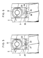
- FIGS. 1 and 2 also illustrate a first embodiment of the present invention.
- a base 2 is mounted on a vehicle body 1 by a bolt 9.
- a slide anchor 3 carrying a slip joint 4 through which a webbing 11 extends is guided by the base 2 movably in the vertical direction as viewed in FIG. 2.
- the webbing 11 is therefore supported by the slip joint 4.
- the slide anchor 3 is provided with a lock pin 5, which is selectively allowed to engage a desired one of plural engagement holes 8 bored through the base 2 so that the slide anchor 3 is locked on the base 2.
- the lock pin 5 is urged by a spring 6 toward the vehicle body, whereby its engagement with the desired one of engagement holes 8 is maintained.
- the anchor 3 can be unlocked from the base 2 by pulling out the lock pin 5 with a knob 7 attached to the lock pin 5 on a side opposite to the vehicle body 1.
- FIGS. 1 and 2 also illustrate a cover 10, nut 12 and bolt 13 for mounting the slip joint 4 on the slide anchor 3, and a pin guide 14 fixed on the slide anchor 3 to guide the lock pin 5.
- a stopper 20 is generally employed to prevent the slide anchor 3 from moving down beyond a certain distance.
- the stopper 20 is formed by lancing and bending up a portion of the base or by using a separate member.
- a resin-made slide shoe 15 fixed on an end portion of the slide anchor 3 in order to permit smooth movement of the slide anchor 3 is brought into abutment against the stopper 20, whereby any further downward movement of the slide anchor 3 is prevented.
- a slide shoe fixed on an end portion of a slide anchor is designed to abut against a stopper portion of a base so that the stopper portion and the slide anchor, both made of a metal, are prevented from abutment.
- an adjustable shoulder an chorage which comprises a base defining a plurality of engagement portions distributed at predetermined intervals along the length of the base, a slide anchor provided movably under guidance along the base and carrying a joint on which a webbing is supported, a lock member provided on the slide anchor, the lock member being selectively engageable with the engagement portions, a stopper provided on a side of one end of the base so that movement of the slide anchor can be limited, and an impact absorber means interposed between the stopper and the slide anchor, the impact absorber means being flexible when brought into abutment against the stopper.
- the impact absorber means can absorb an impact when the slide anchor is moved to the lowest height. The occurrence of impact noise can therefore be reduced.
- FIGS. 1 through 4 an adjustable shoulder anchorage according to a first em bodiment of the invention will be described.
- the button 7 is pulled up leftwards as viewed in FIG. 2 so that the lock pin 5 is disengaged from the engagement hole 8.
- the slide anchor 3 becomes movable.
- the slide shoe 15 provided on a lower end portion of the slide anchor 3 is brought into abutment against the stopper 20 provided on the base 2 so that the slide anchor 3 is prevented from any further downward movement.
- an abutment 16 of the slide shoe 15, at which the slide shoe 15 is brought into abutment against the stopper 20, is formed thinner on the side of the slide anchor 3, whereby a spacing 30 is formed between the slide shoe 15 and an proximal end portion of the slide anchor 3.
- the lanced portions 27 of the slide shoe 25 are brought into abutment against the stopper 20 on the base 2 so that the slide anchor 3 is stopped by the stopper 20.
- the lanced portions 27 are caused to flex upwardly by the stopper 20. Therefore, an impact is absorbed and the occurrence of impact noise is reduced.
- An abutment 18 of a slide shoe 35 at which the slide shoe 35 is brought into abutment against the stopper 20, is formed as an arched portion 36 which bulges out toward the stopper 20.
- the abutment 18 of the slide shoe 35 is formed in an arcuate configuration so that the slide shoe 35 bulges out at the abutment 18 toward the stopper 20.
- a spacing 30 is formed between the arched portion 36 and a proximal end portion of the slide anchor 3.
- the arched portion 36 of the slide shoe 35 is brought into abutment against the stopper 20 on the base 2 so that the slide anchor 3 is stopped by the stopper 20.
- the arched portion 36 is caused to flex upwardly by the stopper 20. Therefore, an impact is absorbed and the occurrence of impact noise is reduced.
- the lanced portions 49 of the slide shoe 45 are brought into abutment against the stopper 20 on the base 2 so that the slide anchor 3 is stopped by the stopper 20.
- the lanced portions 49 are caused to flex upwardly by the stopper 20. Therefore, an impact is absorbed and the occurrence of impact noise is reduced.
- a lower end portion of a slide anchor 53 is cut off as an indentation, so that a spacing 30 is formed between the slide anchor 53 and a slide shoe 55.
- the lower end portion of the slide anchor 53 is cut off at a location opposing to an abutment 56 of the slide shoe 55, at which abutment 56 the slide shoe 55 is brought into abutment against the stopper 20, whereby the spacing 30 is formed between the slide shoe 55 and the slide anchor 53.
- the abutment 56 of the slide shoe 55 is brought into abutment against the stopper 20 on the base 2 so that the slide anchor 53 is stopped by the stopper 20.
- the abutment 56 of the slide shoe 55 is caused to flex upwardly by the stopper 20. Therefore, an impact is absorbed and the occurrence of impact noise is reduced.
Landscapes
- Engineering & Computer Science (AREA)
- Mechanical Engineering (AREA)
- Automotive Seat Belt Assembly (AREA)
- Footwear And Its Accessory, Manufacturing Method And Apparatuses (AREA)
Applications Claiming Priority (2)
| Application Number | Priority Date | Filing Date | Title |
|---|---|---|---|
| JP87209/89 | 1989-07-25 | ||
| JP1989087209U JPH0326654U (de) | 1989-07-25 | 1989-07-25 |
Publications (3)
| Publication Number | Publication Date |
|---|---|
| EP0410377A2 true EP0410377A2 (de) | 1991-01-30 |
| EP0410377A3 EP0410377A3 (en) | 1992-02-05 |
| EP0410377B1 EP0410377B1 (de) | 1994-11-30 |
Family
ID=13908558
Family Applications (1)
| Application Number | Title | Priority Date | Filing Date |
|---|---|---|---|
| EP90114155A Expired - Lifetime EP0410377B1 (de) | 1989-07-25 | 1990-07-24 | Verstellbare Schulterverankerung |
Country Status (5)
| Country | Link |
|---|---|
| US (1) | US5066043A (de) |
| EP (1) | EP0410377B1 (de) |
| JP (1) | JPH0326654U (de) |
| CA (1) | CA2021855C (de) |
| DE (1) | DE69014460T2 (de) |
Cited By (1)
| Publication number | Priority date | Publication date | Assignee | Title |
|---|---|---|---|---|
| ITBO20080529A1 (it) * | 2008-08-28 | 2010-02-28 | Seat S R L | Sedile per automezzi per il pubblico trasporto |
Families Citing this family (11)
| Publication number | Priority date | Publication date | Assignee | Title |
|---|---|---|---|---|
| JP2540263B2 (ja) * | 1992-04-20 | 1996-10-02 | 有限会社睦道研究所 | ショルダアジャスタ装置およびその組立方法 |
| US5366244A (en) * | 1993-10-25 | 1994-11-22 | Trw Vehicle Safety System Inc. | Flexible height adjuster for a vehicle safety belt |
| US5924731A (en) * | 1998-06-22 | 1999-07-20 | Trw Vehicle Safety Systems Inc. | Height adjuster for seat belt webbing |
| US6123391A (en) * | 1999-03-31 | 2000-09-26 | Breed Automotive Technology, Inc. | Adjustable track and slide mechanism |
| KR100379963B1 (ko) * | 2000-12-13 | 2003-04-16 | 현대자동차주식회사 | 다방향 시트벨트의 위치 조절 장치 |
| CA2623115A1 (en) * | 2007-03-02 | 2008-09-02 | M2K, Llc. | Seat assembly for a vehicle and a method of manufacturing the same |
| US20100052378A1 (en) * | 2008-08-29 | 2010-03-04 | Syntec Seating Solutions, Llc. | Seat assembly for a vehicle |
| US8123293B2 (en) * | 2008-12-15 | 2012-02-28 | Syntec Seating Solutions Llc | Seat assembly with rotatable seat bottom |
| US20130127230A1 (en) * | 2011-11-21 | 2013-05-23 | Anthony Fini | Vehicle shoulder belt extension |
| JP2016030536A (ja) * | 2014-07-29 | 2016-03-07 | タカタ株式会社 | シートベルト装置 |
| CN109268360A (zh) * | 2018-08-30 | 2019-01-25 | 苏州大学 | 一种快速插拔连接锁紧装置 |
Citations (5)
| Publication number | Priority date | Publication date | Assignee | Title |
|---|---|---|---|---|
| FR2537003A1 (fr) * | 1982-07-20 | 1984-06-08 | Takata Kojyo Co | Pince de ceinture de securite |
| DE3406047A1 (de) * | 1983-08-04 | 1985-02-21 | TRW Repa GmbH, 7071 Alfdorf | Beschlag fuer einen sicherheitsgurt fuer kraftfahrzeuge |
| DE3431678A1 (de) * | 1984-01-19 | 1985-08-22 | Autoliv GmbH, 2200 Elmshorn | Hoehenverstellbare befestigungs- oder umlenkvorrichtung fuer den sicherheitsgurt eines sicherheitssystems in kraftfahrzeugen |
| EP0290621A1 (de) * | 1986-11-26 | 1988-11-17 | Takata Corporation | Verankerungsanordnung für sicherheitsgurte |
| EP0315184A1 (de) * | 1987-11-06 | 1989-05-10 | Nippon Seiko Kabushiki Kaisha | In Schulterhöhe einstellbarer Verankerungsmechanismus |
Family Cites Families (7)
| Publication number | Priority date | Publication date | Assignee | Title |
|---|---|---|---|---|
| JPS606370Y2 (ja) * | 1979-05-16 | 1985-02-28 | トヨタ自動車株式会社 | ウエビングスライダロツク装置 |
| US4508363A (en) * | 1982-02-11 | 1985-04-02 | Ase (Uk) Limited | Adjustable seat belt anchorage |
| US4536011A (en) * | 1983-02-14 | 1985-08-20 | Nsk-Warner K. K. | Position adjuster for seat belt |
| SE8303683D0 (sv) * | 1983-06-28 | 1983-06-28 | Hakansson Bengt Erik W | Feste for sekerhetsbelte |
| US4720147A (en) * | 1985-06-07 | 1988-01-19 | Juichiro Takada | Adjustable vehicle seat belt anchor |
| JPS6282861A (ja) * | 1985-10-08 | 1987-04-16 | Nec Corp | フアクシミリ装置 |
| JPS63110153A (ja) * | 1986-10-15 | 1988-05-14 | 山形日本電気株式会社 | 柔軟性薬液容器 |
-
1989
- 1989-07-25 JP JP1989087209U patent/JPH0326654U/ja active Pending
-
1990
- 1990-07-24 EP EP90114155A patent/EP0410377B1/de not_active Expired - Lifetime
- 1990-07-24 CA CA002021855A patent/CA2021855C/en not_active Expired - Fee Related
- 1990-07-24 DE DE69014460T patent/DE69014460T2/de not_active Expired - Fee Related
- 1990-07-25 US US07/557,002 patent/US5066043A/en not_active Expired - Lifetime
Patent Citations (5)
| Publication number | Priority date | Publication date | Assignee | Title |
|---|---|---|---|---|
| FR2537003A1 (fr) * | 1982-07-20 | 1984-06-08 | Takata Kojyo Co | Pince de ceinture de securite |
| DE3406047A1 (de) * | 1983-08-04 | 1985-02-21 | TRW Repa GmbH, 7071 Alfdorf | Beschlag fuer einen sicherheitsgurt fuer kraftfahrzeuge |
| DE3431678A1 (de) * | 1984-01-19 | 1985-08-22 | Autoliv GmbH, 2200 Elmshorn | Hoehenverstellbare befestigungs- oder umlenkvorrichtung fuer den sicherheitsgurt eines sicherheitssystems in kraftfahrzeugen |
| EP0290621A1 (de) * | 1986-11-26 | 1988-11-17 | Takata Corporation | Verankerungsanordnung für sicherheitsgurte |
| EP0315184A1 (de) * | 1987-11-06 | 1989-05-10 | Nippon Seiko Kabushiki Kaisha | In Schulterhöhe einstellbarer Verankerungsmechanismus |
Cited By (1)
| Publication number | Priority date | Publication date | Assignee | Title |
|---|---|---|---|---|
| ITBO20080529A1 (it) * | 2008-08-28 | 2010-02-28 | Seat S R L | Sedile per automezzi per il pubblico trasporto |
Also Published As
| Publication number | Publication date |
|---|---|
| CA2021855A1 (en) | 1991-01-26 |
| EP0410377B1 (de) | 1994-11-30 |
| DE69014460T2 (de) | 1995-05-04 |
| JPH0326654U (de) | 1991-03-18 |
| EP0410377A3 (en) | 1992-02-05 |
| DE69014460D1 (de) | 1995-01-12 |
| CA2021855C (en) | 1996-01-09 |
| US5066043A (en) | 1991-11-19 |
Similar Documents
| Publication | Publication Date | Title |
|---|---|---|
| EP0410377A2 (de) | Verstellbare Schulterverankerung | |
| CA1158619A (en) | Floating lock mount for a seat belt retractor | |
| US4068887A (en) | Seat mountings | |
| EP0289628B1 (de) | Verankerungsanordnung für sitzgurte | |
| EP1501700B1 (de) | Kopfstütze-führungshülse | |
| CA2058062A1 (en) | Manual seat adjuster with dual locking means | |
| US4466666A (en) | Seat belt anchor assembly | |
| US4470618A (en) | Adjustable seat belt anchorage | |
| US4577888A (en) | Seat belt anchor assembly | |
| EP0098458B1 (de) | Sitzgurt-Verankerungseinrichtung | |
| KR0175938B1 (ko) | 숄더어저스터 | |
| US4720147A (en) | Adjustable vehicle seat belt anchor | |
| JP2832168B2 (ja) | ウェビング位置調節装置 | |
| EP0290621B1 (de) | Verankerungsanordnung für sicherheitsgurte | |
| CA1283841C (en) | Seat slide structure | |
| JP2838103B2 (ja) | 車のシートの調節装置 | |
| KR970007367B1 (ko) | 차량용 안전벨트의 수동조절위치 고정장치 | |
| EP0041859A1 (de) | Fahrzeugsitzgurt-Anschlussvorrichtung | |
| US5083735A (en) | Vehicle seat | |
| US4867477A (en) | Device for maintaining a strap of a safety belt in an adjustable position | |
| EP0306122A2 (de) | Sicherheitsgurtvorrichtung | |
| JPH06276Y2 (ja) | アジャスタブルショルダアンカ装置のピラ−トリム取付構造 | |
| JPH06275Y2 (ja) | アジャスタブルショルダアンカ装置のガ−ニッシュ構造 | |
| KR100367075B1 (ko) | 이동식 안전막대를 갖는 자동차 시트 | |
| JP2545287Y2 (ja) | アジャストショルダーアンカー装置 |
Legal Events
| Date | Code | Title | Description |
|---|---|---|---|
| PUAI | Public reference made under article 153(3) epc to a published international application that has entered the european phase |
Free format text: ORIGINAL CODE: 0009012 |
|
| AK | Designated contracting states |
Kind code of ref document: A2 Designated state(s): DE FR GB SE |
|
| 17P | Request for examination filed |
Effective date: 19901220 |
|
| PUAL | Search report despatched |
Free format text: ORIGINAL CODE: 0009013 |
|
| AK | Designated contracting states |
Kind code of ref document: A3 Designated state(s): DE FR GB SE |
|
| 17Q | First examination report despatched |
Effective date: 19930715 |
|
| GRAA | (expected) grant |
Free format text: ORIGINAL CODE: 0009210 |
|
| AK | Designated contracting states |
Kind code of ref document: B1 Designated state(s): DE FR GB SE |
|
| REF | Corresponds to: |
Ref document number: 69014460 Country of ref document: DE Date of ref document: 19950112 |
|
| PG25 | Lapsed in a contracting state [announced via postgrant information from national office to epo] |
Ref country code: SE Effective date: 19950228 |
|
| ET | Fr: translation filed | ||
| PLBE | No opposition filed within time limit |
Free format text: ORIGINAL CODE: 0009261 |
|
| STAA | Information on the status of an ep patent application or granted ep patent |
Free format text: STATUS: NO OPPOSITION FILED WITHIN TIME LIMIT |
|
| 26N | No opposition filed | ||
| PGFP | Annual fee paid to national office [announced via postgrant information from national office to epo] |
Ref country code: FR Payment date: 19960709 Year of fee payment: 7 |
|
| PGFP | Annual fee paid to national office [announced via postgrant information from national office to epo] |
Ref country code: GB Payment date: 19960715 Year of fee payment: 7 |
|
| PG25 | Lapsed in a contracting state [announced via postgrant information from national office to epo] |
Ref country code: GB Free format text: LAPSE BECAUSE OF NON-PAYMENT OF DUE FEES Effective date: 19970724 |
|
| GBPC | Gb: european patent ceased through non-payment of renewal fee |
Effective date: 19970724 |
|
| PG25 | Lapsed in a contracting state [announced via postgrant information from national office to epo] |
Ref country code: FR Free format text: LAPSE BECAUSE OF NON-PAYMENT OF DUE FEES Effective date: 19980331 |
|
| REG | Reference to a national code |
Ref country code: FR Ref legal event code: ST |
|
| PGFP | Annual fee paid to national office [announced via postgrant information from national office to epo] |
Ref country code: DE Payment date: 19990723 Year of fee payment: 10 |
|
| PG25 | Lapsed in a contracting state [announced via postgrant information from national office to epo] |
Ref country code: DE Free format text: LAPSE BECAUSE OF NON-PAYMENT OF DUE FEES Effective date: 20010501 |