EP0409643B1 - Kontinuierliches Frittiergerät unter Vakuum - Google Patents
Kontinuierliches Frittiergerät unter Vakuum Download PDFInfo
- Publication number
- EP0409643B1 EP0409643B1 EP90307949A EP90307949A EP0409643B1 EP 0409643 B1 EP0409643 B1 EP 0409643B1 EP 90307949 A EP90307949 A EP 90307949A EP 90307949 A EP90307949 A EP 90307949A EP 0409643 B1 EP0409643 B1 EP 0409643B1
- Authority
- EP
- European Patent Office
- Prior art keywords
- frier
- oil
- frying
- vacuum
- chamber
- Prior art date
- Legal status (The legal status is an assumption and is not a legal conclusion. Google has not performed a legal analysis and makes no representation as to the accuracy of the status listed.)
- Expired - Lifetime
Links
- 239000000463 material Substances 0.000 claims description 102
- 238000000638 solvent extraction Methods 0.000 claims description 28
- 238000011144 upstream manufacturing Methods 0.000 claims description 3
- 238000005507 spraying Methods 0.000 claims 4
- 238000000151 deposition Methods 0.000 description 9
- 238000010276 construction Methods 0.000 description 6
- 238000007599 discharging Methods 0.000 description 5
- 235000013399 edible fruits Nutrition 0.000 description 4
- 238000000034 method Methods 0.000 description 4
- 235000013311 vegetables Nutrition 0.000 description 4
- 238000001816 cooling Methods 0.000 description 3
- 230000008021 deposition Effects 0.000 description 3
- 230000001276 controlling effect Effects 0.000 description 2
- 230000003287 optical effect Effects 0.000 description 2
- 239000012141 concentrate Substances 0.000 description 1
- 230000000694 effects Effects 0.000 description 1
- 235000013305 food Nutrition 0.000 description 1
- 238000010438 heat treatment Methods 0.000 description 1
- 230000007257 malfunction Effects 0.000 description 1
- 238000004519 manufacturing process Methods 0.000 description 1
- 230000000414 obstructive effect Effects 0.000 description 1
- 230000002093 peripheral effect Effects 0.000 description 1
- 230000002035 prolonged effect Effects 0.000 description 1
- 230000001105 regulatory effect Effects 0.000 description 1
- 238000000926 separation method Methods 0.000 description 1
- 235000011888 snacks Nutrition 0.000 description 1
- 229910001220 stainless steel Inorganic materials 0.000 description 1
- 239000010935 stainless steel Substances 0.000 description 1
Images


Classifications
-
- A—HUMAN NECESSITIES
- A47—FURNITURE; DOMESTIC ARTICLES OR APPLIANCES; COFFEE MILLS; SPICE MILLS; SUCTION CLEANERS IN GENERAL
- A47J—KITCHEN EQUIPMENT; COFFEE MILLS; SPICE MILLS; APPARATUS FOR MAKING BEVERAGES
- A47J37/00—Baking; Roasting; Grilling; Frying
- A47J37/12—Deep fat fryers, e.g. for frying fish or chips
- A47J37/1214—Deep fat fryers, e.g. for frying fish or chips the food being transported through an oil-bath
-
- A—HUMAN NECESSITIES
- A23—FOODS OR FOODSTUFFS; TREATMENT THEREOF, NOT COVERED BY OTHER CLASSES
- A23L—FOODS, FOODSTUFFS OR NON-ALCOHOLIC BEVERAGES, NOT OTHERWISE PROVIDED FOR; PREPARATION OR TREATMENT THEREOF
- A23L5/00—Preparation or treatment of foods or foodstuffs, in general; Food or foodstuffs obtained thereby; Materials therefor
- A23L5/10—General methods of cooking foods, e.g. by roasting or frying
Definitions
- the present invention relates to a continuous vacuum frier which supplies material to a vacuum frying chamber while maintaining the vacuum therein and continuously fries the material under the vacuum.
- One of the conventional vacuum friers is disclosed in Japanese Patent Disclosure No. 61-232819. It is of such a type that material to be fried is received within a fry cage which in turn is placed in a vacuum frying chamber.
- the vacuum frying chamber includes double-door type inlet and outlet ports which are sequentially closed to insulate the vacuum frying chamber from atmosphere. Thereafter, the material in the fry cage are fried in the interior of the vacuum frying chamber.
- the technique disclosed in Japanese Patent Disclosure No. 61-232819 has a limited capacity since the material is fried in a batch manner. Particularly, the opening and closing of the double doors in the inlet and outlet ports for each charge of the fry cage provides an obstruction of increase of the throughput capacity.
- the vacuum frier in the prior art is difficult to charge and discharge the material to be fried into and from the fry cages. On discharging, a fry cage must be inverted upside down. Additionally, a mechanism for removing the fried products from the inverted fry cage is bulk and complicated in construction. The fried products may be dropped from the inverted fry cage and damaged in part.
- the system described in Japanese Patent Disclosure No. 62-262954 is adapted to remove the fried products through a slanted conveyor. If such a slanted conveyor is less inclined, the entire system will be increased in length. This raises another problem in that the frying oil remains on the less inclined conveyor for a prolonged time of period. On the other hand, if the conveyor is more inclined, the fried products may be less efficiently removed through the conveyor to the impractical extent.
- Japanese Patent Disclosure No. 62-262954 describes that the entire frying system is housed within a container resisting the vacuum, the container being evacuated through a vacuum pump. However, it does not describe the concrete construction thereof. In general, it is difficult to ensure airtightness in a construction using a screw conveyor for conveying material to be treated. It is also assumed that the materials to be treated cannot be reliably conveyed since most of the material deposit on the screw within the frying oil.
- Another object of the present invention is to provide a continuous vacuum frier which can effectively prevent the material from depositing on conveyor means.
- Still another object of the present invention is to provide a continuous vacuum frier which can positively feed the material within a vacuum frying chamber without creation of any obstructive matter such as clogging.
- a further object is to provide a continuous vacuum frier which is reduced in size and can remove fried products out of the frier efficiently and reliably.
- a further object is to provide a continuous vacuum frier comprising a discharge mechanism which can prevent damage to fried products on discharge.
- a further object is to provide a continuous vacuum frier which can effectively prevent the deposition of materials on the conveyor means and the creation of irregularity in frying degree.
- US-A-40590466 there is disclosed an apparatus for continuously manufacturing a snack food from a fruit or vegetable by frying the fruit or vegetable in oil.
- the apparatus has a conveying means for conveying the fruit or vegetable through frying oil in a vacuum chamber, the conveying means including an endless belt having openings therein and having partitioning members extending outwardly therefrom, the partitioning members defining compartments in which the fruit or vegetable is fried as it is conveyed.
- US-A-3812775 also discloses an apparatus in which an edible product is fried under reduced pressure whilst being conveyed by an apparatus including an endless belt.
- the present invention provides a continuous vacuum frier for conveying material along a path of conveyance within a vacuum frying chamber while maintaining the chamber under vacuum, comprising material conveying means for conveying the material through frying oil, the material conveying means including endless belt means having a plurality of openings formed therein and a plurality of partitioning members extending outwardly from the endless belt means, the partitioning members defining a plurality of compartments which receive the material and in which the material is fried and conveyed, characterised in that the frier further comprises a discharge ramp located at an angle between 40° and 60° relative to horizontal, said ramp being used to discharge fried products from the vacuum frying chamber, in that the partitioning members have a plurality of apertures formed therein, in that the endless belt means is disposed to run parallel to the discharge ramp, and in that the partitioning members are inclined at an angle between 40° and 100° relative to horizontal and have a tip portion slidable or substantially slidable on the discharge ramp.
- the compartments used for frying and conveying are successively located around the endless belt means. All the material simultaneously fed into the frier is received in and conveyed through one and the same compartment and thus can be fried substantially within a given period of time.
- the frying oil is preferably sprayed towards the endless belt means such that the material can be effectively prevented from depositing on the endless belt means or the partitioning members.
- the means for conveying material to be fried can be located solely within the vacuum frying chamber.
- the charge and discharge of the material can be reliably and easily performed in the vacuum frying chamber while maintaining it under vacuum.
- the conveyor means of the present invention can efficiently carry out the frying treatment and the material conveyance since the frying oil can be sprayed toward the endless belt means to prevent the deposition of material on the conveyor means effectively during and after the frying process.
- the continuous vacuum frier further comprises a material supply section having an airtight shutter, a cylinder type feed device disposed below the material supply section for moving the material into the vacuum frying chamber, and a pressure shutoff valve located within the path of conveyance in the cylinder type feed device.
- the continuous vacuum frier can maintain vacuum and efficiently fry the materials by the use of a relatively simple combination of the airtight shutter with the pressure shutoff valve.
- the continuous vacuum frier has less possibility of malfunction since the materials cannot be deposited and clogged on the material supply section wall and others.
- the length of the endless belt means is elongated in the horizontal direction. This causes the size of the entire machine to increase and also becomes hard to remove the frying oil from the endless belt. If the angle of the ramp exceeds 60° , the angle included between the ramp and the partitioning members will be reduced too much since the partitioning members are attached to the endless belt means running parallel to the discharge ramp at an angle of 40° - 100° relative to horizontal. This may cause the fried products to be damaged due to the tendency of depositing on the discharge ramp.
- the fried products are received and conveyed in a compartment defined by the partitioning members. Therefore, the angle of inclination in the discharge ramp can be increased as compared to that which was possible in the prior art. This permits not only to reduce the entire machine in size, but also to render the discharge of the fried products and to prevent the damage of the fried products. Also for such a reason why the fry cage will not be inverted upside down, the entire construction of the frier can be miniaturized and simplified.
- the continuous vacuum frier comprises an oil inlet located upstream in the path of conveyance and an oil outlet disposed downstream in the same path of conveyance.
- the frying oil can be moved in the same direction as that of the material being fried.
- the frying oil aids in conveying the material to be fried.
- the frying oil can effectively prevent the deposition of materials on the conveyor means and the creation of irregularity in frying.
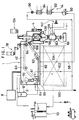
- a continuous vacuum frier constructed according to the present invention, which comprises a vacuum frying chamber 1 for vacuum frying material; a material supply device 2 connected with the vacuum frying chamber 1; and a centrifugal separating device 4 connected with the vacuum frying chamber 1 and adapted to separate the frying oil from the fried products.
- the horizontal pipe section 34 incorporates a feed piston 37 reciprocatable therewithin, which piston 37 is attached to a hydraulic cylinder 36 functioning as a drive for the supply of materials.
- a material supply cover 40 is connected with the horizontal pipe section 34 at a position opposite to the hydraulic cylinder 36 through an automatic ball valve 38 which functions as a pressure shutoff valve.
- the material supply cover 40 is of a cylindrical configuration and extends within the interior of the vacuum frying chamber 1 in a direction perpendicular to the direction of conveyance in the screen conveyor 42.
- a downwardly directed material supply opening 44 is provided in the material supply cover 40 at a position above the screen conveyor 42.
- the material supply cover 40 may be connected with downwardly extending guide means (not shown) which can reliably convey the dropped materials to a material supply position, preferably to a compartment in which the materials are submerged into the frying oil.
- the automatic butterfly valve 32 is automatically opened as materials are supplied to the material hopper 30. After passage of a given time period, the butterfly valve 32 is automatically closed. Subsequently, the electromagnetic valve in the pipe communicating with the vacuum frying chamber 1 is opened to gradually evacuate the interior of the horizontal pipe section 34. Thereafter, the automatic ball valve 38 is automatically opened immediately before the feed piston 37 begins to move the materials to the supply opening 44. As the feed piston 37 is retracted after completion of the feed movement thereof, the automatic ball valve 38 is closed. In such a manner, the material supply device 2 can supply material to the frier while maintaining the vacuum frying chamber 1 under vacuum.
- the screen conveyor 42 for conveying the material in the vacuum frying chamber 1 comprises a plurality of partitioning screens 52 extending substantially outwardly from a screen-like endless belt 50, as shown in Figure 2.
- the width of the vacuum frying chamber 1 in a direction perpendicular to the direction of conveyance in the screen conveyor 42 is substantially equal to the width of the endless belt 50 and the partitioning screens 52.
- a plurality of compartments 54 opening outwardly will be formed on the screen conveyor 42.
- Each of the compartments 54 receives a given amount of material.
- Each of the partitioning screens 52 is inclined relative to the endless belt 50 at such an angle as will be described later.
- the guide pulley 61 is connected with an optical rotary disc 72 which is positioned outside the vacuum frying chamber 1 and rotated through a chain 70.
- the optical disc 72 is disposed between light emitting means 74 and light receiving means 76.
- a curved surface 80 partially surrounds the lower portion of the guide pulley 61.
- the curved surface 80 has a curvature, about the rotational axis of the guide pulley 61, substantially following the locus of the forward edges of the moving partitioning screens 52.
- the lower end of the curved surface 80 is joined to the bottom surface 82 of the vacuum frying chamber 1 while the upper end thereof is coupled with a slanted guide plate 84 for guiding the supplied material into each of the compartments 54.
- the curved surface 80 serves to secure that when each of the compartments 54 is inverted with the top opening thereof being downwardly directed, the material is easily discharged from the compartment 54 through the top opening thereof without clogging. It is preferred that the material is supplied to each of the compartments at the beginning of frying at which part of that compartment begins to be submerged into the frying oil.
- the oil temperature adjusting device 14 maintains the frying oil at a predetermined temperature, for example, any suitable temperature ranged between 80 ° - 120° by circulating the frying oil from the vacuum frying chamber 1 through a cooling unit 92 or heating unit 94 and a filter unit 96 by an oil pump 90.
- the oil temperature adjusting device 14 includes an oil discharge pipe 98 which communicates with a double-bottomed oil tank 93, as shown in Figure 9.
- the double-bottomed oil tank 93 is connected to the vacuum frying chamber 1 through a plurality of small apertures 107 which are formed in a discharge ramp 106, which will be described in detail, at a position adjacent to the end of the path of frying treatment in the screen conveyor 42.
- part of the adjusted oil is returned on the upper portion of the slanted guide plate 84 through an oil return pipe 100. This can prevent the material from depositing on the slanted guide plate 84.
- the frying oil adjusted to the predetermined temperature is returned into the vacuum frying chamber 1 at the upper portion of the slanted guide plate 84, an upper position near the guide pulley 61 and near the position in which the endless belt 50 exits the frying oil.
- the frying oil is then discharged outwardly through small apertures 107 formed in the ramp near the end of the path of frying treatment.
- the frying oil will always flow along the path of material conveyance from the upstream to the downstream side. This can effectively prevent the material from depositing on the conveying means (at the face thereof on the downstream side of each partitioning screen 52).
- the flow of frying oil serves, together with the intermittent motion of the compartments 54, to agitate the material in each of the compartments 54 very well to avoid any irregularity in frying effectively.
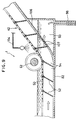
- the endless belt 50 is spaced above the discharge ramp 106 and runs parallel thereto.
- the ramp 106 is disposed at an angle between 40° - 60° , relative to horizontal.
- Each of the partitioning screens 52 is mounted on the endless belt 50 through a fixture 108 such that the angle of the partitioning screen relative to the horizontal line H, that is, the angle of conveyance ⁇ in the partitioning screen is between 40° - 100° , preferably between 80° - 90° .
- Hopper means 111 is disposed below the discharge port 110 of the vacuum frying chamber 1, as shown in Figure 3.
- the hopper means 111 includes an endless discharge belt 112 moveably supported on part of the sidewall 120 and formed of a thin and surface finished sheet of stainless steel. This endless belt 112 is spanned between upper and lower pulleys 114, 116 and a tension roller 118. The endless discharge belt 112 is engaged by a doctor knife 119 at a position wherein the belt 112 passes over the lower pulley 116.
- the hopper means 111 includes a shutter 113 at the lower end thereof.
- the centrifugal separating device 4 is located below the hopper means 111.
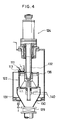
- the centrifugal separating device 4 comprises a centrifugal separator 122 receiving the fried products from the hopper means 111; a drive 124 for driving the centrifugal separator 122; a hopper 130 disposed below the centrifugal separator 122, the hopper 130 having an airtight shutter 129 at the lower end thereof; and an oil collecting barrel 131 for collecting the oil separated from the products by means of the centrifugal separator 122.
- the centrifugal separator 122 is integrally mounted on a rotating drive shaft 132 which in turn is connected to a drive 124 ( Figure 4).
- the centrifugal separator 122 comprises a cylinder member 136 including a number of small apertures 134 formed therethrough; a bottom lid member 138 reciprocatable between a position in which the bottom lid member 138 engages the lower end portion of the cylinder member 136 without gap and another position in which the bottom lid member 138 is spaced apart from the lower end portion of the cylinder member 136 to form a gap through which the fried products can pass; and a bottom lid drive 140 for moving the bottom lid member 138 vertically between said two positions.
- the bottom lid member 138 is substantially of a conical configuration and has a central raised portion and a horizontal flange 139 on the peripheral edge thereof.
- the bottom lid member 138 is biased upwardly under the action of a coil spring 144 which is mounted about a spring core member 142 extending downwardly from the lower end of the rotary shaft 132. Normally, the bottom lid member 138 engages the lower end face of the cylinder member 136 to close the bottom opening thereof.
- the bottom lid member 138 is biased against the cylinder member 136 to close the bottom opening thereof, under the biasing force of the coil spring 144. If a given amount of products are accumulated in the hopper means 111, the shutter 113 is opened to supply the products into the centrifugal separator 122. The supplied products are accumulated in a space defined by the cylinder member 136 and the bottom lid member 138 at its lower section.
- the rotary drive 124 ( Figure 4) is energized to rotate the cylinder and bottom lid members 136, 138 as a unit through the drive shaft 132.
- the rotational velocity may be set at 300 - 1,500 revolutions per minute.
- the products can be moved along the internal face of the cylinder member 136. Since the outer wall of the bottom lid member 138 is raised at its center and inclined outwardly, the products will not concentrate on the bottom face of the cylinder member 136, but be spread throughout the inner wall of the cylinder member. Thus, the oil can be separated from the products substantially uniformly.
- the bottom lid drive 140 is energized to move the bottom lid member 138 downwardly against the biasing force of the coil spring 144.
- said gap will be formed between the lower end face of the cylinder member 136 and the bottom lid member 138.
- the products may drop into the hopper 130 through said gap.
- the bottom lid drive 140 is de-energized to allow the bottom lid member 138 to move upwardly under the action of the coil spring 144.
- the bottom opening of the cylinder member 136 may be closed by the bottom lid member 138, as shown in Figure 5(A).
- the airtight shutter 129 of the hopper 130 communicates with a product discharge chamber 160, as shown in Figure 1.
- the product discharge chamber 160 is provided, at its lower end, with a pressure shutoff valve 161 for discharging the products.
- the product discharge chamber 160 also includes a pressure regulator 162 which is usable on returning the interior of the product discharge chamber from vacuum to normal pressure. It is preferred that the product discharge chamber further includes a cooling mechanism 163 which can cool and set the products such that the products will be effectively avoided from deforming on returning the product discharge chamber from vacuum to normal pressure.
- the airtight shutter 130 When a predetermined amount of products are accumulated in the hopper 130, the airtight shutter 130 is opened to drop the products into the product discharge chamber 160. Thereafter, the airtight shutter 129 is closed. The cooling mechanism 163 is then energized to cool the products to a predetermined temperature. The pressure adjusting mechanism 162 is subsequently energized to return the internal pressure of the product discharge chamber 160 from vacuum to normal pressure. Finally, the pressure shutoff valve 161 is opened so that the products can be removed out of the frier.
- the horizontal pipe section 34, the material feed piston 37 and the material supply cover 40 have a common axis which is aligned with the direction of conveyance in the endless material conveying belt 16.
- the ramp 204 located below the supply port 200 of the supply cover 40 is preferably provided with a plurality of oil outlet ports 202 to which the oil is fed from an oil pump 90 shown in Figure 1. Therefore, the oil is always flowing on the ramp 204 so that the supplied material will not accumulate thereon.
- Figure 7 shows the second embodiment of an oil discharge section according to the present invention, in which components common to those of the first embodiment are denoted by similar reference numerals and will not be described further.
- a plurality of small side apertures 109 are formed in the sides of the path of frying treatment in addition of the small apertures 107 on the discharge ramp 106 for discharging the oil.
- the double-bottomed oil tank 93 located below the discharge ramp 106 and communicating with the small side apertures 109 is provided with a filter 105 for filtrating the used frying oil to eliminated undesirable matters therefrom.
Landscapes
- Chemical & Material Sciences (AREA)
- Engineering & Computer Science (AREA)
- Food Science & Technology (AREA)
- Oil, Petroleum & Natural Gas (AREA)
- Health & Medical Sciences (AREA)
- Nutrition Science (AREA)
- Life Sciences & Earth Sciences (AREA)
- Polymers & Plastics (AREA)
- Frying-Pans Or Fryers (AREA)
- Electrostatic Spraying Apparatus (AREA)
- Financial Or Insurance-Related Operations Such As Payment And Settlement (AREA)
Claims (15)
- Kontinuierlich arbeitende Vakuumfrittiervorrichtung zum Fördern von Material längs eines Förderweges innerhalb einer Vakuumfrittierkammer (1), während die Kammer (1) unter Vakuum gehalten wird, mit einer Materialfördereinrichtung zum Fördern des Materials durch Frittieröl, wobei die Materialfördereinrichtung eine Endlosbandeinrichtung (50) umfaßt, die eine Vielzahl von darin ausgebildeten Öffnungen und eine Vielzahl von Unterteilungsgliedern (52) aufweist, welche sich von der Endlosbandeinrichtung (50) auswärts erstrecker, wobei die Unterteilungsglieder (52) eine Vielzahl von Abteilen (54) definieren, welche das Material aufnehmen und in welchen das Material frittiert und gefördert wird,
dadurch gekennzeichnet,
daß die Frittiervorrichtung weiterhin eine Entladerampe (106) aufweist, welche in einem Winkel zwischen 40 und 60° in bezug auf die Horizontale angeordnet ist, wobei die Rampe verwendet wird, um frittierte Produkte aus der Vakuumfrittierkammer (1) auszugeben, daß die Unterteilungsglieder (52) eine Vielzahl von Öffnungen aufweisen, daß die Endlosbandeinrichtung (50) so angeordnet ist, daß sie parallel zur Entladerampe (106) läuft, und daß die Unterteilungsglieder (52) in einem Winkel zwischen 40 und 100° in bezug auf die Horizontale geneigt sind und einen Spitzenabschnitt aufweisen, der an der Entladerampe (106) gleitbar oder im wesentlichen gleitbar ist. - Frittiervorrichtung nach Anspruch 1, dadurch gekennzeichnet, daß die Materialfördereinrichtung eine Ölsprüheinrichtung umfaßt, um Frittieröl an einer Stelle nahe des Beginnens des Frittierens abwärts zu sprühen.
- Frittiervorrichtung nach Anspruch 1 oder 2, dadurch gekennzeichnet, daß die Materialfördereinrichtung eine Ölsprüheinrichtung (104) aufweist, um Frittieröl an einer Stelle unmittelbar nach Beendigen des Frittierens abwärts zu sprühen.
- Frittiervorrichtung nach einem der Ansprüche 1 bis 3, dadurch gekennzeichnet, daß die Materialfördereinrichtung das Material durch Bewegen der Endlosbandeinrichtung (50) durch das Frittieröl fördert.
- Frittiervorrichtung nach einem der Ansprüche 1 bis 4, dadurch gekennzeichnet, daß eine Materialrufihrsektion mit einem luftdichten Verschluß (32) vorgesehen ist, daß eine zylinderartige Zuführeinrichtung unterhalb der Materialzuführsektion vorgesehen ist, um das Material in die Vakuumfrittierkammer (1) zu fördern, und daß innerhalb des Bewegungsweges der zylinderartigen Zuführeinrichtung eine Druckabsperrventileinrichtung angeordnet ist.
- Frittiervorrichtung nach Anspruch 5, dadurch gekennzeichnet, daß die zylinderartige Zuführeinrichtung ein Zuführglied einschließt, welches in einer Richtung parallel zur Förderrichtung der Materialfördereinrichtung hin- und herbewegbar ist.
- Frittiervorrichtung nach Anspruch 5, dadurch gekennzeichnet, daß die zylinderartige Zuführeinrichtung ein Zuführglied (37) einschließt, welches in einer Richtung senkrecht zur Förderrichtung der Materialfördereinrichtung hin- und herbewegbar ist.
- Frittiervorrichtung nach Anspruch 5, dadurch gekennzeichnet, daß die zylinderartige Zuführeinrichtung einen Entladeabschnitt und Seitenwandabschnitte einschließt, die unterhalb der Ebene des Entladeabschnittes angeordnet sind und auf welchen das Frittieröl fließt.
- Frittiervorrichtung nach Anspruch 8, dadurch gekennzeichnet, daß das Frittieröl fähig ist, sich auswärts durch eine Öffnungseinrichtung in dem Seitenwandabschnitt zu bewegen.
- Frittiervorrichtung nach Anspruch 8, dadurch gekennzeichnet, daß eine Einrichtung vorgesehen ist, mit welcher das Frittieröl von dem oberen Abschnitt der Frittiervorrichtung versprühbar ist.
- Frittiervorrichtung nach einem der Ansprüche 1 bis 10, dadurch gekennzeichnet, daß die Unterteilungsglieder (52) die Form von Sieben aufweisen.
- Frittiervorrichtung nach einem der Ansprüche 1 bis 10, dadurch gekennzeichnet, daß der Winkel der Unterteilungsglieder (52) gegen die Horizontale zwischen 80 und 90° liegt.
- Frittiervorrichtung nach einem der Ansprüche 1 bis 12, dadurch gekennzeichnet, daß ein Öleinlaß stromauf von der Materialfördereinrichtung und ein Ölauslaß stromab von der Materialfördereinrichtung angeordnet sind.
- Frittiervorrichtung nach Anspruch 13, dadurch gekennzeichnet, daß die Vakuumfrittierkammer (1) einen Doppelboden aufweist, und daß das Frittieröl, welches aus der Vakuumfrittierkammer (1) überfließt, in einen Raum (53) einführbar ist, der von den beiden Bodenwänden der Vakuumfrittierkammer (1) definiert ist.
- Frittiervorrichtung nach Anspruch 14, dadurch gekennzeichnet, daß eine Filtereinrichtung (105) zwischen den beiden Bodenwänden der Vakuumfrittierkammer (1) angeordnet ist.
Applications Claiming Priority (2)
| Application Number | Priority Date | Filing Date | Title |
|---|---|---|---|
| JP188015/89 | 1989-07-20 | ||
| JP1188015A JP2750907B2 (ja) | 1989-07-20 | 1989-07-20 | 連続式フライヤー |
Publications (3)
| Publication Number | Publication Date |
|---|---|
| EP0409643A2 EP0409643A2 (de) | 1991-01-23 |
| EP0409643A3 EP0409643A3 (en) | 1992-04-01 |
| EP0409643B1 true EP0409643B1 (de) | 1995-09-27 |
Family
ID=16216167
Family Applications (1)
| Application Number | Title | Priority Date | Filing Date |
|---|---|---|---|
| EP90307949A Expired - Lifetime EP0409643B1 (de) | 1989-07-20 | 1990-07-20 | Kontinuierliches Frittiergerät unter Vakuum |
Country Status (6)
| Country | Link |
|---|---|
| US (1) | US5182982A (de) |
| EP (1) | EP0409643B1 (de) |
| JP (1) | JP2750907B2 (de) |
| KR (1) | KR930000355B1 (de) |
| CA (1) | CA2021360C (de) |
| DE (1) | DE69022659T2 (de) |
Families Citing this family (17)
| Publication number | Priority date | Publication date | Assignee | Title |
|---|---|---|---|---|
| JP2559911B2 (ja) * | 1991-03-01 | 1996-12-04 | 日清食品株式会社 | 油揚げ麺塊の製造方法 |
| JP3544606B2 (ja) * | 1997-06-30 | 2004-07-21 | 旭エンジニアリング株式会社 | 連続式真空乾燥装置と方法 |
| WO2001089320A1 (en) * | 2000-05-24 | 2001-11-29 | Fruit Chips B.V. | Method and device for frying products |
| US20050226984A1 (en) * | 2004-04-08 | 2005-10-13 | Addington Donald R | System and method of manufacturing character-shaped snack food product |
| US8549993B2 (en) * | 2008-04-14 | 2013-10-08 | Spinfry, Inc. | Cooking device with slidable drawer |
| US20120017773A1 (en) * | 2008-08-18 | 2012-01-26 | Spinfry, Inc. | Fryer device with oil removal and conveyor system |
| US20120070553A1 (en) | 2010-09-20 | 2012-03-22 | Conagra Foods Lamb Weston, Inc. | Conveyor-based frying apparatus and methods of use |
| CR20110253A (es) | 2011-05-12 | 2011-10-20 | Univ Costa Rica | Freidora al vacio |
| US8613969B2 (en) | 2011-07-22 | 2013-12-24 | Frito-Lay North America, Inc. | Low pressure deoiling of fried food product |
| AU2012356034B2 (en) * | 2011-12-22 | 2017-08-31 | Melnyczuk, Tania Maria | Method and apparatus for the preparation of a crisp food product |
| CN102986756B (zh) * | 2012-12-06 | 2015-04-22 | 江南大学 | 一种用于调理食品的微波与真空油炸一体化装置及高效油炸方法 |
| DE202012105071U1 (de) | 2012-12-27 | 2013-03-01 | Jiangnan University | Eine Vorrichtung zum Verarbeiten der Lebensmittel, welche die Funktionen von Mikrowellen- und Vakuumbraten integriert |
| CN104791507A (zh) * | 2014-01-18 | 2015-07-22 | 陈长清 | 一种单元式闸板密封阀 |
| CN106305867B (zh) * | 2016-11-22 | 2018-12-07 | 全氏食品机械(上海)有限公司 | 全自动真空油炸装置 |
| CN109874817B (zh) * | 2019-04-02 | 2023-11-14 | 秦皇岛锦鸿机械设备加工有限公司 | 真空油炸机 |
| US12569087B2 (en) * | 2021-08-27 | 2026-03-10 | Marmon Foodservice Technologies, Inc. | Broiler discharge ramp |
| NL2031667B1 (en) * | 2022-04-22 | 2023-11-07 | Marel Further Proc Bv | Continuous frying device |
Family Cites Families (26)
| Publication number | Priority date | Publication date | Assignee | Title |
|---|---|---|---|---|
| US1518206A (en) * | 1923-12-26 | 1924-12-09 | Frank C Kramer | Cooking apparatus |
| US2042262A (en) * | 1933-04-29 | 1936-05-26 | Alexander S T Lagaard | Distributing device for doughnut machines |
| US2134088A (en) * | 1937-12-29 | 1938-10-25 | Louis K Obdyke | Machine for popping popcorn and vending the same |
| US2272175A (en) * | 1938-10-01 | 1942-02-10 | Us Rubber Co | Method and apparatus for filtering |
| FR998725A (fr) * | 1949-10-06 | 1952-01-22 | Appareil à débit continu pour la friture des aliments | |
| US2603143A (en) * | 1950-05-11 | 1952-07-15 | George E Saenz | Pastry shell frying machine |
| US2696776A (en) * | 1951-04-24 | 1954-12-14 | Mcbean Res Corp | Machine for filling cans |
| US2917008A (en) * | 1955-12-12 | 1959-12-15 | Kipnis Abraham | Deep-fried extruded-dough comestible machine |
| US2889930A (en) * | 1956-08-02 | 1959-06-09 | David M Tholl | Self discharging base bearing centrifugal |
| US2932401A (en) * | 1957-06-13 | 1960-04-12 | American Tool & Machine Compan | Suspended centrifugal apparatus |
| US2886439A (en) * | 1958-03-18 | 1959-05-12 | Frito Company | Method for producing potato chips |
| US3022722A (en) * | 1960-03-07 | 1962-02-27 | Luk O Ma Corp | Automatic cooking apparatus |
| FR1306757A (fr) * | 1961-09-08 | 1962-10-19 | Installation pour la cuisson des pommes de terre frites et | |
| US3218959A (en) * | 1963-12-26 | 1965-11-23 | John D Swisher | Machine for making potato chips |
| US3812775A (en) * | 1966-10-28 | 1974-05-28 | Inst Bewaring En Verwerking Va | Process and apparatus for preparing fried edible products |
| US3585923A (en) * | 1968-10-21 | 1971-06-22 | Leo R Waller | Automatic food fryer |
| US3573861A (en) * | 1969-01-06 | 1971-04-06 | Dawn Donut Co Inc | Self-cleaning fryer apparatus |
| US3573059A (en) * | 1969-07-10 | 1971-03-30 | Etsuji Yuki | Method of preventing the deterioration of frying oils in frying apparatuses and a hood for use on such apparatuses |
| US4059046A (en) * | 1976-07-02 | 1977-11-22 | Kanro Co. Ltd. | Apparatus for manufacturing a snack food whose raw material is fruitage or vegetables |
| JPS591518Y2 (ja) * | 1979-01-19 | 1984-01-17 | 真夫 安達 | 動物、魚貝類等の残渣油揚装置 |
| US4372200A (en) * | 1981-05-04 | 1983-02-08 | Heat And Control, Inc. | Direct fired fryer with wiper means |
| US4488478A (en) * | 1983-07-08 | 1984-12-18 | J. C. Pitman Company, Inc. | Continuous fryer for potato chips and other snack foods |
| JPS60147331U (ja) * | 1984-03-08 | 1985-09-30 | サミ−工業株式会社 | 自動フライヤ |
| DE3786400T2 (de) * | 1986-04-23 | 1994-02-17 | Vos Ind Pty Ltd | Kochvorrichtung. |
| US4887524A (en) * | 1988-04-11 | 1989-12-19 | International Seafood Engineering, Inc. | Shrimp cooking apparatus |
| US4882984A (en) * | 1988-10-07 | 1989-11-28 | Raytheon Company | Constant temperature fryer assembly |
-
1989
- 1989-07-20 JP JP1188015A patent/JP2750907B2/ja not_active Expired - Fee Related
-
1990
- 1990-07-17 CA CA002021360A patent/CA2021360C/en not_active Expired - Fee Related
- 1990-07-19 US US07/554,378 patent/US5182982A/en not_active Expired - Fee Related
- 1990-07-20 DE DE69022659T patent/DE69022659T2/de not_active Expired - Fee Related
- 1990-07-20 EP EP90307949A patent/EP0409643B1/de not_active Expired - Lifetime
- 1990-07-20 KR KR1019900011060A patent/KR930000355B1/ko not_active Expired - Fee Related
Also Published As
| Publication number | Publication date |
|---|---|
| KR910002359A (ko) | 1991-02-25 |
| CA2021360C (en) | 1994-02-22 |
| DE69022659D1 (de) | 1995-11-02 |
| CA2021360A1 (en) | 1991-01-21 |
| DE69022659T2 (de) | 1996-05-02 |
| KR930000355B1 (ko) | 1993-01-16 |
| EP0409643A3 (en) | 1992-04-01 |
| EP0409643A2 (de) | 1991-01-23 |
| US5182982A (en) | 1993-02-02 |
| JPH0351019A (ja) | 1991-03-05 |
| JP2750907B2 (ja) | 1998-05-18 |
Similar Documents
| Publication | Publication Date | Title |
|---|---|---|
| EP0409643B1 (de) | Kontinuierliches Frittiergerät unter Vakuum | |
| US5223137A (en) | Centrifugal separation apparatus with solids discharge controlled by reciprocating bottom lid | |
| KR960011515B1 (ko) | 연속튀김장치 | |
| US3274920A (en) | Continuous deep fat fryer | |
| US5316128A (en) | Particulate material feeder | |
| US4946584A (en) | Hydraulic product separator | |
| US12551055B2 (en) | Floating particles removal within a food fryer | |
| JP2706826B2 (ja) | 連続式減圧フライヤー | |
| JP2627558B2 (ja) | 連続式減圧フライヤー | |
| JP2808139B2 (ja) | 減圧遠心分離方法及び装置 | |
| JPH089075Y2 (ja) | 連続式減圧フライヤー | |
| EP0618776B1 (de) | Kochgerät | |
| JP2750908B2 (ja) | 連続式フライヤー | |
| JP2604237B2 (ja) | 遠心分離装置 | |
| AU668372B2 (en) | Cooking apparatus | |
| JPH0678690A (ja) | 連続式減圧フライ方法及び装置 | |
| WO2025006612A1 (en) | Machine for applying a granular coating to food | |
| JPH067255A (ja) | 減圧フライヤー | |
| JPH067256A (ja) | 連続式減圧フライヤー |
Legal Events
| Date | Code | Title | Description |
|---|---|---|---|
| PUAI | Public reference made under article 153(3) epc to a published international application that has entered the european phase |
Free format text: ORIGINAL CODE: 0009012 |
|
| AK | Designated contracting states |
Kind code of ref document: A2 Designated state(s): DE FR GB |
|
| 17P | Request for examination filed |
Effective date: 19901204 |
|
| R17P | Request for examination filed (corrected) |
Effective date: 19901204 |
|
| PUAL | Search report despatched |
Free format text: ORIGINAL CODE: 0009013 |
|
| AK | Designated contracting states |
Kind code of ref document: A3 Designated state(s): DE FR GB |
|
| 17Q | First examination report despatched |
Effective date: 19940209 |
|
| GRAA | (expected) grant |
Free format text: ORIGINAL CODE: 0009210 |
|
| AK | Designated contracting states |
Kind code of ref document: B1 Designated state(s): DE FR GB |
|
| ET | Fr: translation filed | ||
| REF | Corresponds to: |
Ref document number: 69022659 Country of ref document: DE Date of ref document: 19951102 |
|
| PLBE | No opposition filed within time limit |
Free format text: ORIGINAL CODE: 0009261 |
|
| STAA | Information on the status of an ep patent application or granted ep patent |
Free format text: STATUS: NO OPPOSITION FILED WITHIN TIME LIMIT |
|
| 26N | No opposition filed | ||
| PGFP | Annual fee paid to national office [announced via postgrant information from national office to epo] |
Ref country code: GB Payment date: 19990528 Year of fee payment: 10 |
|
| PGFP | Annual fee paid to national office [announced via postgrant information from national office to epo] |
Ref country code: FR Payment date: 19990615 Year of fee payment: 10 |
|
| PGFP | Annual fee paid to national office [announced via postgrant information from national office to epo] |
Ref country code: DE Payment date: 19990827 Year of fee payment: 10 |
|
| PG25 | Lapsed in a contracting state [announced via postgrant information from national office to epo] |
Ref country code: GB Free format text: LAPSE BECAUSE OF NON-PAYMENT OF DUE FEES Effective date: 20000720 |
|
| GBPC | Gb: european patent ceased through non-payment of renewal fee |
Effective date: 20000720 |
|
| PG25 | Lapsed in a contracting state [announced via postgrant information from national office to epo] |
Ref country code: FR Free format text: LAPSE BECAUSE OF NON-PAYMENT OF DUE FEES Effective date: 20010330 |
|
| REG | Reference to a national code |
Ref country code: FR Ref legal event code: ST |
|
| PG25 | Lapsed in a contracting state [announced via postgrant information from national office to epo] |
Ref country code: DE Free format text: LAPSE BECAUSE OF NON-PAYMENT OF DUE FEES Effective date: 20010501 |