EP0409643B1 - Continuous vacuum fryer - Google Patents
Continuous vacuum fryer Download PDFInfo
- Publication number
- EP0409643B1 EP0409643B1 EP90307949A EP90307949A EP0409643B1 EP 0409643 B1 EP0409643 B1 EP 0409643B1 EP 90307949 A EP90307949 A EP 90307949A EP 90307949 A EP90307949 A EP 90307949A EP 0409643 B1 EP0409643 B1 EP 0409643B1
- Authority
- EP
- European Patent Office
- Prior art keywords
- frier
- oil
- frying
- vacuum
- chamber
- Prior art date
- Legal status (The legal status is an assumption and is not a legal conclusion. Google has not performed a legal analysis and makes no representation as to the accuracy of the status listed.)
- Expired - Lifetime
Links
- 239000000463 material Substances 0.000 claims description 102
- 238000000638 solvent extraction Methods 0.000 claims description 28
- 238000011144 upstream manufacturing Methods 0.000 claims description 3
- 238000005507 spraying Methods 0.000 claims 4
- 238000000151 deposition Methods 0.000 description 9
- 238000010276 construction Methods 0.000 description 6
- 238000007599 discharging Methods 0.000 description 5
- 235000013399 edible fruits Nutrition 0.000 description 4
- 238000000034 method Methods 0.000 description 4
- 235000013311 vegetables Nutrition 0.000 description 4
- 238000001816 cooling Methods 0.000 description 3
- 230000008021 deposition Effects 0.000 description 3
- 230000001276 controlling effect Effects 0.000 description 2
- 230000003287 optical effect Effects 0.000 description 2
- 239000012141 concentrate Substances 0.000 description 1
- 230000000694 effects Effects 0.000 description 1
- 235000013305 food Nutrition 0.000 description 1
- 238000010438 heat treatment Methods 0.000 description 1
- 230000007257 malfunction Effects 0.000 description 1
- 238000004519 manufacturing process Methods 0.000 description 1
- 230000000414 obstructive effect Effects 0.000 description 1
- 230000002093 peripheral effect Effects 0.000 description 1
- 230000002035 prolonged effect Effects 0.000 description 1
- 230000001105 regulatory effect Effects 0.000 description 1
- 238000000926 separation method Methods 0.000 description 1
- 235000011888 snacks Nutrition 0.000 description 1
- 229910001220 stainless steel Inorganic materials 0.000 description 1
- 239000010935 stainless steel Substances 0.000 description 1
Images


Classifications
-
- A—HUMAN NECESSITIES
- A47—FURNITURE; DOMESTIC ARTICLES OR APPLIANCES; COFFEE MILLS; SPICE MILLS; SUCTION CLEANERS IN GENERAL
- A47J—KITCHEN EQUIPMENT; COFFEE MILLS; SPICE MILLS; APPARATUS FOR MAKING BEVERAGES
- A47J37/00—Baking; Roasting; Grilling; Frying
- A47J37/12—Deep fat fryers, e.g. for frying fish or chips
- A47J37/1214—Deep fat fryers, e.g. for frying fish or chips the food being transported through an oil-bath
-
- A—HUMAN NECESSITIES
- A23—FOODS OR FOODSTUFFS; TREATMENT THEREOF, NOT COVERED BY OTHER CLASSES
- A23L—FOODS, FOODSTUFFS, OR NON-ALCOHOLIC BEVERAGES, NOT COVERED BY SUBCLASSES A21D OR A23B-A23J; THEIR PREPARATION OR TREATMENT, e.g. COOKING, MODIFICATION OF NUTRITIVE QUALITIES, PHYSICAL TREATMENT; PRESERVATION OF FOODS OR FOODSTUFFS, IN GENERAL
- A23L5/00—Preparation or treatment of foods or foodstuffs, in general; Food or foodstuffs obtained thereby; Materials therefor
- A23L5/10—General methods of cooking foods, e.g. by roasting or frying
Definitions
- the present invention relates to a continuous vacuum frier which supplies material to a vacuum frying chamber while maintaining the vacuum therein and continuously fries the material under the vacuum.
- One of the conventional vacuum friers is disclosed in Japanese Patent Disclosure No. 61-232819. It is of such a type that material to be fried is received within a fry cage which in turn is placed in a vacuum frying chamber.
- the vacuum frying chamber includes double-door type inlet and outlet ports which are sequentially closed to insulate the vacuum frying chamber from atmosphere. Thereafter, the material in the fry cage are fried in the interior of the vacuum frying chamber.
- the technique disclosed in Japanese Patent Disclosure No. 61-232819 has a limited capacity since the material is fried in a batch manner. Particularly, the opening and closing of the double doors in the inlet and outlet ports for each charge of the fry cage provides an obstruction of increase of the throughput capacity.
- the vacuum frier in the prior art is difficult to charge and discharge the material to be fried into and from the fry cages. On discharging, a fry cage must be inverted upside down. Additionally, a mechanism for removing the fried products from the inverted fry cage is bulk and complicated in construction. The fried products may be dropped from the inverted fry cage and damaged in part.
- the system described in Japanese Patent Disclosure No. 62-262954 is adapted to remove the fried products through a slanted conveyor. If such a slanted conveyor is less inclined, the entire system will be increased in length. This raises another problem in that the frying oil remains on the less inclined conveyor for a prolonged time of period. On the other hand, if the conveyor is more inclined, the fried products may be less efficiently removed through the conveyor to the impractical extent.
- Japanese Patent Disclosure No. 62-262954 describes that the entire frying system is housed within a container resisting the vacuum, the container being evacuated through a vacuum pump. However, it does not describe the concrete construction thereof. In general, it is difficult to ensure airtightness in a construction using a screw conveyor for conveying material to be treated. It is also assumed that the materials to be treated cannot be reliably conveyed since most of the material deposit on the screw within the frying oil.
- Another object of the present invention is to provide a continuous vacuum frier which can effectively prevent the material from depositing on conveyor means.
- Still another object of the present invention is to provide a continuous vacuum frier which can positively feed the material within a vacuum frying chamber without creation of any obstructive matter such as clogging.
- a further object is to provide a continuous vacuum frier which is reduced in size and can remove fried products out of the frier efficiently and reliably.
- a further object is to provide a continuous vacuum frier comprising a discharge mechanism which can prevent damage to fried products on discharge.
- a further object is to provide a continuous vacuum frier which can effectively prevent the deposition of materials on the conveyor means and the creation of irregularity in frying degree.
- US-A-40590466 there is disclosed an apparatus for continuously manufacturing a snack food from a fruit or vegetable by frying the fruit or vegetable in oil.
- the apparatus has a conveying means for conveying the fruit or vegetable through frying oil in a vacuum chamber, the conveying means including an endless belt having openings therein and having partitioning members extending outwardly therefrom, the partitioning members defining compartments in which the fruit or vegetable is fried as it is conveyed.
- US-A-3812775 also discloses an apparatus in which an edible product is fried under reduced pressure whilst being conveyed by an apparatus including an endless belt.
- the present invention provides a continuous vacuum frier for conveying material along a path of conveyance within a vacuum frying chamber while maintaining the chamber under vacuum, comprising material conveying means for conveying the material through frying oil, the material conveying means including endless belt means having a plurality of openings formed therein and a plurality of partitioning members extending outwardly from the endless belt means, the partitioning members defining a plurality of compartments which receive the material and in which the material is fried and conveyed, characterised in that the frier further comprises a discharge ramp located at an angle between 40° and 60° relative to horizontal, said ramp being used to discharge fried products from the vacuum frying chamber, in that the partitioning members have a plurality of apertures formed therein, in that the endless belt means is disposed to run parallel to the discharge ramp, and in that the partitioning members are inclined at an angle between 40° and 100° relative to horizontal and have a tip portion slidable or substantially slidable on the discharge ramp.
- the compartments used for frying and conveying are successively located around the endless belt means. All the material simultaneously fed into the frier is received in and conveyed through one and the same compartment and thus can be fried substantially within a given period of time.
- the frying oil is preferably sprayed towards the endless belt means such that the material can be effectively prevented from depositing on the endless belt means or the partitioning members.
- the means for conveying material to be fried can be located solely within the vacuum frying chamber.
- the charge and discharge of the material can be reliably and easily performed in the vacuum frying chamber while maintaining it under vacuum.
- the conveyor means of the present invention can efficiently carry out the frying treatment and the material conveyance since the frying oil can be sprayed toward the endless belt means to prevent the deposition of material on the conveyor means effectively during and after the frying process.
- the continuous vacuum frier further comprises a material supply section having an airtight shutter, a cylinder type feed device disposed below the material supply section for moving the material into the vacuum frying chamber, and a pressure shutoff valve located within the path of conveyance in the cylinder type feed device.
- the continuous vacuum frier can maintain vacuum and efficiently fry the materials by the use of a relatively simple combination of the airtight shutter with the pressure shutoff valve.
- the continuous vacuum frier has less possibility of malfunction since the materials cannot be deposited and clogged on the material supply section wall and others.
- the length of the endless belt means is elongated in the horizontal direction. This causes the size of the entire machine to increase and also becomes hard to remove the frying oil from the endless belt. If the angle of the ramp exceeds 60° , the angle included between the ramp and the partitioning members will be reduced too much since the partitioning members are attached to the endless belt means running parallel to the discharge ramp at an angle of 40° - 100° relative to horizontal. This may cause the fried products to be damaged due to the tendency of depositing on the discharge ramp.
- the fried products are received and conveyed in a compartment defined by the partitioning members. Therefore, the angle of inclination in the discharge ramp can be increased as compared to that which was possible in the prior art. This permits not only to reduce the entire machine in size, but also to render the discharge of the fried products and to prevent the damage of the fried products. Also for such a reason why the fry cage will not be inverted upside down, the entire construction of the frier can be miniaturized and simplified.
- the continuous vacuum frier comprises an oil inlet located upstream in the path of conveyance and an oil outlet disposed downstream in the same path of conveyance.
- the frying oil can be moved in the same direction as that of the material being fried.
- the frying oil aids in conveying the material to be fried.
- the frying oil can effectively prevent the deposition of materials on the conveyor means and the creation of irregularity in frying.
- a continuous vacuum frier constructed according to the present invention, which comprises a vacuum frying chamber 1 for vacuum frying material; a material supply device 2 connected with the vacuum frying chamber 1; and a centrifugal separating device 4 connected with the vacuum frying chamber 1 and adapted to separate the frying oil from the fried products.
- the horizontal pipe section 34 incorporates a feed piston 37 reciprocatable therewithin, which piston 37 is attached to a hydraulic cylinder 36 functioning as a drive for the supply of materials.
- a material supply cover 40 is connected with the horizontal pipe section 34 at a position opposite to the hydraulic cylinder 36 through an automatic ball valve 38 which functions as a pressure shutoff valve.
- the material supply cover 40 is of a cylindrical configuration and extends within the interior of the vacuum frying chamber 1 in a direction perpendicular to the direction of conveyance in the screen conveyor 42.
- a downwardly directed material supply opening 44 is provided in the material supply cover 40 at a position above the screen conveyor 42.
- the material supply cover 40 may be connected with downwardly extending guide means (not shown) which can reliably convey the dropped materials to a material supply position, preferably to a compartment in which the materials are submerged into the frying oil.
- the automatic butterfly valve 32 is automatically opened as materials are supplied to the material hopper 30. After passage of a given time period, the butterfly valve 32 is automatically closed. Subsequently, the electromagnetic valve in the pipe communicating with the vacuum frying chamber 1 is opened to gradually evacuate the interior of the horizontal pipe section 34. Thereafter, the automatic ball valve 38 is automatically opened immediately before the feed piston 37 begins to move the materials to the supply opening 44. As the feed piston 37 is retracted after completion of the feed movement thereof, the automatic ball valve 38 is closed. In such a manner, the material supply device 2 can supply material to the frier while maintaining the vacuum frying chamber 1 under vacuum.
- the screen conveyor 42 for conveying the material in the vacuum frying chamber 1 comprises a plurality of partitioning screens 52 extending substantially outwardly from a screen-like endless belt 50, as shown in Figure 2.
- the width of the vacuum frying chamber 1 in a direction perpendicular to the direction of conveyance in the screen conveyor 42 is substantially equal to the width of the endless belt 50 and the partitioning screens 52.
- a plurality of compartments 54 opening outwardly will be formed on the screen conveyor 42.
- Each of the compartments 54 receives a given amount of material.
- Each of the partitioning screens 52 is inclined relative to the endless belt 50 at such an angle as will be described later.
- the guide pulley 61 is connected with an optical rotary disc 72 which is positioned outside the vacuum frying chamber 1 and rotated through a chain 70.
- the optical disc 72 is disposed between light emitting means 74 and light receiving means 76.
- a curved surface 80 partially surrounds the lower portion of the guide pulley 61.
- the curved surface 80 has a curvature, about the rotational axis of the guide pulley 61, substantially following the locus of the forward edges of the moving partitioning screens 52.
- the lower end of the curved surface 80 is joined to the bottom surface 82 of the vacuum frying chamber 1 while the upper end thereof is coupled with a slanted guide plate 84 for guiding the supplied material into each of the compartments 54.
- the curved surface 80 serves to secure that when each of the compartments 54 is inverted with the top opening thereof being downwardly directed, the material is easily discharged from the compartment 54 through the top opening thereof without clogging. It is preferred that the material is supplied to each of the compartments at the beginning of frying at which part of that compartment begins to be submerged into the frying oil.
- the oil temperature adjusting device 14 maintains the frying oil at a predetermined temperature, for example, any suitable temperature ranged between 80 ° - 120° by circulating the frying oil from the vacuum frying chamber 1 through a cooling unit 92 or heating unit 94 and a filter unit 96 by an oil pump 90.
- the oil temperature adjusting device 14 includes an oil discharge pipe 98 which communicates with a double-bottomed oil tank 93, as shown in Figure 9.
- the double-bottomed oil tank 93 is connected to the vacuum frying chamber 1 through a plurality of small apertures 107 which are formed in a discharge ramp 106, which will be described in detail, at a position adjacent to the end of the path of frying treatment in the screen conveyor 42.
- part of the adjusted oil is returned on the upper portion of the slanted guide plate 84 through an oil return pipe 100. This can prevent the material from depositing on the slanted guide plate 84.
- the frying oil adjusted to the predetermined temperature is returned into the vacuum frying chamber 1 at the upper portion of the slanted guide plate 84, an upper position near the guide pulley 61 and near the position in which the endless belt 50 exits the frying oil.
- the frying oil is then discharged outwardly through small apertures 107 formed in the ramp near the end of the path of frying treatment.
- the frying oil will always flow along the path of material conveyance from the upstream to the downstream side. This can effectively prevent the material from depositing on the conveying means (at the face thereof on the downstream side of each partitioning screen 52).
- the flow of frying oil serves, together with the intermittent motion of the compartments 54, to agitate the material in each of the compartments 54 very well to avoid any irregularity in frying effectively.
- the endless belt 50 is spaced above the discharge ramp 106 and runs parallel thereto.
- the ramp 106 is disposed at an angle between 40° - 60° , relative to horizontal.
- Each of the partitioning screens 52 is mounted on the endless belt 50 through a fixture 108 such that the angle of the partitioning screen relative to the horizontal line H, that is, the angle of conveyance ⁇ in the partitioning screen is between 40° - 100° , preferably between 80° - 90° .
- Hopper means 111 is disposed below the discharge port 110 of the vacuum frying chamber 1, as shown in Figure 3.
- the hopper means 111 includes an endless discharge belt 112 moveably supported on part of the sidewall 120 and formed of a thin and surface finished sheet of stainless steel. This endless belt 112 is spanned between upper and lower pulleys 114, 116 and a tension roller 118. The endless discharge belt 112 is engaged by a doctor knife 119 at a position wherein the belt 112 passes over the lower pulley 116.
- the hopper means 111 includes a shutter 113 at the lower end thereof.
- the centrifugal separating device 4 is located below the hopper means 111.
- the centrifugal separating device 4 comprises a centrifugal separator 122 receiving the fried products from the hopper means 111; a drive 124 for driving the centrifugal separator 122; a hopper 130 disposed below the centrifugal separator 122, the hopper 130 having an airtight shutter 129 at the lower end thereof; and an oil collecting barrel 131 for collecting the oil separated from the products by means of the centrifugal separator 122.
- the centrifugal separator 122 is integrally mounted on a rotating drive shaft 132 which in turn is connected to a drive 124 ( Figure 4).
- the centrifugal separator 122 comprises a cylinder member 136 including a number of small apertures 134 formed therethrough; a bottom lid member 138 reciprocatable between a position in which the bottom lid member 138 engages the lower end portion of the cylinder member 136 without gap and another position in which the bottom lid member 138 is spaced apart from the lower end portion of the cylinder member 136 to form a gap through which the fried products can pass; and a bottom lid drive 140 for moving the bottom lid member 138 vertically between said two positions.
- the bottom lid member 138 is substantially of a conical configuration and has a central raised portion and a horizontal flange 139 on the peripheral edge thereof.
- the bottom lid member 138 is biased upwardly under the action of a coil spring 144 which is mounted about a spring core member 142 extending downwardly from the lower end of the rotary shaft 132. Normally, the bottom lid member 138 engages the lower end face of the cylinder member 136 to close the bottom opening thereof.
- the bottom lid member 138 is biased against the cylinder member 136 to close the bottom opening thereof, under the biasing force of the coil spring 144. If a given amount of products are accumulated in the hopper means 111, the shutter 113 is opened to supply the products into the centrifugal separator 122. The supplied products are accumulated in a space defined by the cylinder member 136 and the bottom lid member 138 at its lower section.
- the rotary drive 124 ( Figure 4) is energized to rotate the cylinder and bottom lid members 136, 138 as a unit through the drive shaft 132.
- the rotational velocity may be set at 300 - 1,500 revolutions per minute.
- the products can be moved along the internal face of the cylinder member 136. Since the outer wall of the bottom lid member 138 is raised at its center and inclined outwardly, the products will not concentrate on the bottom face of the cylinder member 136, but be spread throughout the inner wall of the cylinder member. Thus, the oil can be separated from the products substantially uniformly.
- the bottom lid drive 140 is energized to move the bottom lid member 138 downwardly against the biasing force of the coil spring 144.
- said gap will be formed between the lower end face of the cylinder member 136 and the bottom lid member 138.
- the products may drop into the hopper 130 through said gap.
- the bottom lid drive 140 is de-energized to allow the bottom lid member 138 to move upwardly under the action of the coil spring 144.
- the bottom opening of the cylinder member 136 may be closed by the bottom lid member 138, as shown in Figure 5(A).
- the airtight shutter 129 of the hopper 130 communicates with a product discharge chamber 160, as shown in Figure 1.
- the product discharge chamber 160 is provided, at its lower end, with a pressure shutoff valve 161 for discharging the products.
- the product discharge chamber 160 also includes a pressure regulator 162 which is usable on returning the interior of the product discharge chamber from vacuum to normal pressure. It is preferred that the product discharge chamber further includes a cooling mechanism 163 which can cool and set the products such that the products will be effectively avoided from deforming on returning the product discharge chamber from vacuum to normal pressure.
- the airtight shutter 130 When a predetermined amount of products are accumulated in the hopper 130, the airtight shutter 130 is opened to drop the products into the product discharge chamber 160. Thereafter, the airtight shutter 129 is closed. The cooling mechanism 163 is then energized to cool the products to a predetermined temperature. The pressure adjusting mechanism 162 is subsequently energized to return the internal pressure of the product discharge chamber 160 from vacuum to normal pressure. Finally, the pressure shutoff valve 161 is opened so that the products can be removed out of the frier.
- the horizontal pipe section 34, the material feed piston 37 and the material supply cover 40 have a common axis which is aligned with the direction of conveyance in the endless material conveying belt 16.
- the ramp 204 located below the supply port 200 of the supply cover 40 is preferably provided with a plurality of oil outlet ports 202 to which the oil is fed from an oil pump 90 shown in Figure 1. Therefore, the oil is always flowing on the ramp 204 so that the supplied material will not accumulate thereon.
- Figure 7 shows the second embodiment of an oil discharge section according to the present invention, in which components common to those of the first embodiment are denoted by similar reference numerals and will not be described further.
- a plurality of small side apertures 109 are formed in the sides of the path of frying treatment in addition of the small apertures 107 on the discharge ramp 106 for discharging the oil.
- the double-bottomed oil tank 93 located below the discharge ramp 106 and communicating with the small side apertures 109 is provided with a filter 105 for filtrating the used frying oil to eliminated undesirable matters therefrom.
Description
- The present invention relates to a continuous vacuum frier which supplies material to a vacuum frying chamber while maintaining the vacuum therein and continuously fries the material under the vacuum.
- One of the conventional vacuum friers is disclosed in Japanese Patent Disclosure No. 61-232819. It is of such a type that material to be fried is received within a fry cage which in turn is placed in a vacuum frying chamber. The vacuum frying chamber includes double-door type inlet and outlet ports which are sequentially closed to insulate the vacuum frying chamber from atmosphere. Thereafter, the material in the fry cage are fried in the interior of the vacuum frying chamber.
- The other type of vacuum frier is disclosed in Japanese Patent Disclosure No. 62-262954, in which material to be fried is fed through and fried in frying oil under vacuum by the use of a screw conveyor.
- The technique disclosed in Japanese Patent Disclosure No. 61-232819 has a limited capacity since the material is fried in a batch manner. Particularly, the opening and closing of the double doors in the inlet and outlet ports for each charge of the fry cage provides an obstruction of increase of the throughput capacity. The vacuum frier in the prior art is difficult to charge and discharge the material to be fried into and from the fry cages. On discharging, a fry cage must be inverted upside down. Additionally, a mechanism for removing the fried products from the inverted fry cage is bulk and complicated in construction. The fried products may be dropped from the inverted fry cage and damaged in part.
- In the technique disclosed in Japanese Patent Disclosure No. 62-262954, it is difficult to convey all the material through the frying oil positively by means of the screw conveyor within a given period of time. The time period required to treat the materials is variable. The variable time period raises a problem in that the fried products are variable in quality.
- The system described in Japanese Patent Disclosure No. 62-262954 is adapted to remove the fried products through a slanted conveyor. If such a slanted conveyor is less inclined, the entire system will be increased in length. This raises another problem in that the frying oil remains on the less inclined conveyor for a prolonged time of period. On the other hand, if the conveyor is more inclined, the fried products may be less efficiently removed through the conveyor to the impractical extent.
- Japanese Patent Disclosure No. 62-262954 describes that the entire frying system is housed within a container resisting the vacuum, the container being evacuated through a vacuum pump. However, it does not describe the concrete construction thereof. In general, it is difficult to ensure airtightness in a construction using a screw conveyor for conveying material to be treated. It is also assumed that the materials to be treated cannot be reliably conveyed since most of the material deposit on the screw within the frying oil.
- In view of the aforementioned problems in the prior art, it is an object of the present invention to provide a continuous vacuum frier which has a sufficient throughput capacity and which can treat material in frying oil substantially within a given period of time.
- Another object of the present invention is to provide a continuous vacuum frier which can effectively prevent the material from depositing on conveyor means.
- Still another object of the present invention is to provide a continuous vacuum frier which can positively feed the material within a vacuum frying chamber without creation of any obstructive matter such as clogging.
- A further object is to provide a continuous vacuum frier which is reduced in size and can remove fried products out of the frier efficiently and reliably.
- A further object is to provide a continuous vacuum frier comprising a discharge mechanism which can prevent damage to fried products on discharge.
- A further object is to provide a continuous vacuum frier which can effectively prevent the deposition of materials on the conveyor means and the creation of irregularity in frying degree.
- In US-A-4059046, there is disclosed an apparatus for continuously manufacturing a snack food from a fruit or vegetable by frying the fruit or vegetable in oil. The apparatus has a conveying means for conveying the fruit or vegetable through frying oil in a vacuum chamber, the conveying means including an endless belt having openings therein and having partitioning members extending outwardly therefrom, the partitioning members defining compartments in which the fruit or vegetable is fried as it is conveyed.
- US-A-3812775 also discloses an apparatus in which an edible product is fried under reduced pressure whilst being conveyed by an apparatus including an endless belt.
- Further apparatus in which edible products are fried whilst being conveyed through frying oil by a conveying means including an endless belt are disclosed in FR-A-998725, US-A-2917008 and FR-A-1306757.
- The present invention provides a continuous vacuum frier for conveying material along a path of conveyance within a vacuum frying chamber while maintaining the chamber under vacuum, comprising material conveying means for conveying the material through frying oil, the material conveying means including endless belt means having a plurality of openings formed therein and a plurality of partitioning members extending outwardly from the endless belt means, the partitioning members defining a plurality of compartments which receive the material and in which the material is fried and conveyed, characterised in that the frier further comprises a discharge ramp located at an angle between 40° and 60° relative to horizontal, said ramp being used to discharge fried products from the vacuum frying chamber, in that the partitioning members have a plurality of apertures formed therein, in that the endless belt means is disposed to run parallel to the discharge ramp, and in that the partitioning members are inclined at an angle between 40° and 100° relative to horizontal and have a tip portion slidable or substantially slidable on the discharge ramp.
- In accordance with the one embodiment of the present invention, the compartments used for frying and conveying are successively located around the endless belt means. All the material simultaneously fed into the frier is received in and conveyed through one and the same compartment and thus can be fried substantially within a given period of time.
- The frying oil is preferably sprayed towards the endless belt means such that the material can be effectively prevented from depositing on the endless belt means or the partitioning members.
- In such an arrangement, the means for conveying material to be fried can be located solely within the vacuum frying chamber. Thus, the charge and discharge of the material can be reliably and easily performed in the vacuum frying chamber while maintaining it under vacuum.
- In accordance with the present invention, all the material can be fried substantially within a given period of time to provide vacuum fried products with a stable quality.
- The conveyor means of the present invention can efficiently carry out the frying treatment and the material conveyance since the frying oil can be sprayed toward the endless belt means to prevent the deposition of material on the conveyor means effectively during and after the frying process.
- Preferably, the continuous vacuum frier further comprises a material supply section having an airtight shutter, a cylinder type feed device disposed below the material supply section for moving the material into the vacuum frying chamber, and a pressure shutoff valve located within the path of conveyance in the cylinder type feed device.
- When the pressure shutoff valve is closed and the airtight shutter in the material supply section is opened, material is supplied into the frier. Thereafter, the airtight shutter is closed. Subsequently, the pressure shutoff valve is opened and the cylinder type feed device is then actuated to feed the materials supplied through the material supply section into the vacuum frying chamber. After such a conveyance, the pressure shutoff valve is closed and the next materials are again supplied into the frier through the material supply section.
- In this case the continuous vacuum frier can maintain vacuum and efficiently fry the materials by the use of a relatively simple combination of the airtight shutter with the pressure shutoff valve. The continuous vacuum frier has less possibility of malfunction since the materials cannot be deposited and clogged on the material supply section wall and others.
- If the discharge ramp is inclined with an angle smaller than 40° relative to horizontal, the length of the endless belt means is elongated in the horizontal direction. This causes the size of the entire machine to increase and also becomes hard to remove the frying oil from the endless belt. If the angle of the ramp exceeds 60° , the angle included between the ramp and the partitioning members will be reduced too much since the partitioning members are attached to the endless belt means running parallel to the discharge ramp at an angle of 40° - 100° relative to horizontal. This may cause the fried products to be damaged due to the tendency of depositing on the discharge ramp.
- If the partitioning members are positioned with an angle relative to horizontal larger than 100° , any fried product may be damaged by entering between the partitioning members and the discharge ramp. If the angle of the partitioning members is smaller than 40 ° , the fried products remain on the partitioning members and cannot be fed to the subsequent processing step such as centrifugal separation.
- The fried products are received and conveyed in a compartment defined by the partitioning members. Therefore, the angle of inclination in the discharge ramp can be increased as compared to that which was possible in the prior art. This permits not only to reduce the entire machine in size, but also to render the discharge of the fried products and to prevent the damage of the fried products. Also for such a reason why the fry cage will not be inverted upside down, the entire construction of the frier can be miniaturized and simplified.
- Preferably, the continuous vacuum frier comprises an oil inlet located upstream in the path of conveyance and an oil outlet disposed downstream in the same path of conveyance.
- In such an arrangement, the frying oil can be moved in the same direction as that of the material being fried. Thus, the frying oil aids in conveying the material to be fried. Additionally, the frying oil can effectively prevent the deposition of materials on the conveyor means and the creation of irregularity in frying.
- For a better understanding of the invention, and to show how the same may be carried into effect, reference will now be made by way of example only to the accompanying drawings, in which:
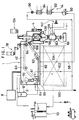
- Figure 1 is a view showing the arrangement of one embodiment of a continuous vacuum frier constructed in accordance with the present invention.
- Figure 2 is a perspective view of the material supply section.
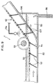
- Figure 3 is a cross-sectional view showing a ramp and duct for conveying the fried products out of the frier.
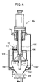
- Figure 4 is a cross-sectional view of the centrifugal separator.
- Figures 5(A)-5(D) illustrate the centrifugal separator at various operating positions.
- Figure 6 is a cross-sectional view of another modified construction in the material supply section.
- Figure 7 is a view showing, in an enlarged scale, an oil discharge section in the second embodiment of the present invention.
- Figure 8 is a view showing, in an enlarged scale, an oil discharge section in the third embodiment of the present invention.
- Figure 9 is a view showing, in an enlarged scale, another modified construction in the oil discharge section.
- Referring now to Figure 1, there is shown one embodiment of a continuous vacuum frier constructed according to the present invention, which comprises a vacuum frying chamber 1 for vacuum frying material; a
material supply device 2 connected with the vacuum frying chamber 1; and acentrifugal separating device 4 connected with the vacuum frying chamber 1 and adapted to separate the frying oil from the fried products. - The vacuum frying chamber 1 is also connected with an evacuating
unit 8 for evacuating the vacuum frying chamber 1; anoil level detector 10 for detecting the level of the oil in the vacuum frying chamber 1; anoil supply tank 12 for supplying the frying oil to the vacuum frying chamber 1; an oiltemperature adjusting device 14 for adjusting the temperature of the oil in the vacuum frying chamber 1; and abelt drive device 18 for driving conveyor means such as ascreen conveyor 42 for conveying the materials into the vacuum frying chamber 1. - As seen from Figure 2, the
material supply device 2 comprises amaterial hopper 30 for externally receiving material to be fried; anautomatic butterfly valve 32 located under thematerial hopper 30 and functioning as an airtight shutter; and ahorizontal pipe section 34 located below theautomatic butterfly valve 32 and adapted to receive the material moved past theautomatic butterfly valve 32. Thehorizontal pipe section 34 is connected to the vacuum frying chamber 1 through pipe means (not shown) which includes an electromagnetically actuated valve and a flow regulating valve. As the airtight shutter, the automatic butterfly valve may be replaced by any other suitable valve means such as automatic ball valve, automatic gate valve or the like. - The
horizontal pipe section 34 incorporates afeed piston 37 reciprocatable therewithin, whichpiston 37 is attached to ahydraulic cylinder 36 functioning as a drive for the supply of materials. - A
material supply cover 40 is connected with thehorizontal pipe section 34 at a position opposite to thehydraulic cylinder 36 through anautomatic ball valve 38 which functions as a pressure shutoff valve. Thematerial supply cover 40 is of a cylindrical configuration and extends within the interior of the vacuum frying chamber 1 in a direction perpendicular to the direction of conveyance in thescreen conveyor 42. A downwardly directedmaterial supply opening 44 is provided in thematerial supply cover 40 at a position above thescreen conveyor 42. Thematerial supply cover 40 may be connected with downwardly extending guide means (not shown) which can reliably convey the dropped materials to a material supply position, preferably to a compartment in which the materials are submerged into the frying oil. - The
automatic butterfly valve 32 is automatically opened as materials are supplied to thematerial hopper 30. After passage of a given time period, thebutterfly valve 32 is automatically closed. Subsequently, the electromagnetic valve in the pipe communicating with the vacuum frying chamber 1 is opened to gradually evacuate the interior of thehorizontal pipe section 34. Thereafter, theautomatic ball valve 38 is automatically opened immediately before thefeed piston 37 begins to move the materials to thesupply opening 44. As thefeed piston 37 is retracted after completion of the feed movement thereof, theautomatic ball valve 38 is closed. In such a manner, thematerial supply device 2 can supply material to the frier while maintaining the vacuum frying chamber 1 under vacuum. - The
screen conveyor 42 for conveying the material in the vacuum frying chamber 1 comprises a plurality ofpartitioning screens 52 extending substantially outwardly from a screen-likeendless belt 50, as shown in Figure 2. The width of the vacuum frying chamber 1 in a direction perpendicular to the direction of conveyance in thescreen conveyor 42 is substantially equal to the width of theendless belt 50 and the partitioning screens 52. Thus, a plurality ofcompartments 54 opening outwardly will be formed on thescreen conveyor 42. Each of thecompartments 54 receives a given amount of material. Each of the partitioning screens 52 is inclined relative to theendless belt 50 at such an angle as will be described later. - As shown in Figure 1, the
screen conveyor 42 is guided by means of three guide pulleys 60, 61 and 62 and intermittently driven by means of adrive pulley 64. Thescreen conveyor 42 runs substantially along a parallelogram-shaped path. The section of thescreen conveyor 42 corresponding to the bottom side of the parallelogram is submerged in the frying oil. In this bottom conveyor section, the material will be fried. Thescreen conveyor 42 is intermittently moved one time for each time period ranged between ten seconds and ten minutes by a distance corresponding to the dimension of one compartment measured in the direction of conveyance on thescreen conveyor 42. - As seen from Figure 1 and 2, the
guide pulley 61 is connected with anoptical rotary disc 72 which is positioned outside the vacuum frying chamber 1 and rotated through achain 70. Theoptical disc 72 is disposed between light emitting means 74 and light receiving means 76. Thus, such a sensor can detect the rotational angle of theguide pulley 61 and thus the distance of conveyance of thescreen conveyor 42. - A
curved surface 80 partially surrounds the lower portion of theguide pulley 61. Thecurved surface 80 has a curvature, about the rotational axis of theguide pulley 61, substantially following the locus of the forward edges of the moving partitioning screens 52. The lower end of thecurved surface 80 is joined to thebottom surface 82 of the vacuum frying chamber 1 while the upper end thereof is coupled with aslanted guide plate 84 for guiding the supplied material into each of thecompartments 54. Thecurved surface 80 serves to secure that when each of thecompartments 54 is inverted with the top opening thereof being downwardly directed, the material is easily discharged from thecompartment 54 through the top opening thereof without clogging. It is preferred that the material is supplied to each of the compartments at the beginning of frying at which part of that compartment begins to be submerged into the frying oil. - The level of oil within the vacuum frying chamber 1 is sensed by the
oil level detector 10 shown in Figure 1. If the frying oil in the vacuum frying chamber 1 is consumed below a predetermined level, it is detected by theoil level detector 10 which in turn actuates an oil level controlling system (not shown). The oil level controlling system then provides a signal to theoil supply tank 12 which in turn is actuated to re-supply new frying oil. In the illustrated embodiment, the level of oil is maintained above theendless belt 50 in the horizontal path of conveyance wherein each of thecompartments 54 is positioned upside down. Depending on the type of oil and the temperature of the oil, however, the level of the oil may be below theendless belt 50. - The oil
temperature adjusting device 14 maintains the frying oil at a predetermined temperature, for example, any suitable temperature ranged between 80 ° - 120° by circulating the frying oil from the vacuum frying chamber 1 through acooling unit 92 orheating unit 94 and afilter unit 96 by anoil pump 90. - The oil
temperature adjusting device 14 includes anoil discharge pipe 98 which communicates with a double-bottomedoil tank 93, as shown in Figure 9. The double-bottomedoil tank 93 is connected to the vacuum frying chamber 1 through a plurality ofsmall apertures 107 which are formed in adischarge ramp 106, which will be described in detail, at a position adjacent to the end of the path of frying treatment in thescreen conveyor 42. - After the oil has been adjusted to a predetermined temperature by the oil
temperature adjusting device 14, part of the adjusted oil is returned on the upper portion of the slantedguide plate 84 through anoil return pipe 100. This can prevent the material from depositing on the slantedguide plate 84. - After adjustment with respect to the temperature thereof, another part of the oil is passed along an
oil return pipe 102 and sprayed substantially toward theguide pulley 61 located at the bottom run of thescreen conveyor 42. Thus, the floating material being fried can be prevented from depositing on thescreen conveyor 42 and also the material deposited on thescreen conveyor 42 can be separated therefrom. The sprayed oil portion also serves to agitate the frying oil so as to prevent any irregularity in frying. Additionally, the sprayed oil portion can add thermal energy to the body of frying oil at the beginning of the frying operation. - It is preferred that still another part of the oil adjusted to the predetermined temperature is further sprayed toward the
endless belt 50 at a position adjacent to the lower portion of thedischarge ramp 106 for discharging the fried products from the vacuum frying chamber 1 to thecentrifugal separating device 4 through apipe 104, that is, near a position at which theendless belt 50 exits the frying oil. This serves to separate the fried products from theendless belt 50. - As described previously, the frying oil adjusted to the predetermined temperature is returned into the vacuum frying chamber 1 at the upper portion of the slanted
guide plate 84, an upper position near theguide pulley 61 and near the position in which theendless belt 50 exits the frying oil. The frying oil is then discharged outwardly throughsmall apertures 107 formed in the ramp near the end of the path of frying treatment. As a result, the frying oil will always flow along the path of material conveyance from the upstream to the downstream side. This can effectively prevent the material from depositing on the conveying means (at the face thereof on the downstream side of each partitioning screen 52). Furthermore, the flow of frying oil serves, together with the intermittent motion of thecompartments 54, to agitate the material in each of thecompartments 54 very well to avoid any irregularity in frying effectively. - As shown in Figure 3, the
endless belt 50 is spaced above thedischarge ramp 106 and runs parallel thereto. Theramp 106 is disposed at an angle between 40° - 60° , relative to horizontal. Each of the partitioning screens 52 is mounted on theendless belt 50 through afixture 108 such that the angle of the partitioning screen relative to the horizontal line H, that is, the angle of conveyance α in the partitioning screen is between 40° - 100° , preferably between 80° - 90° . - Hopper means 111 is disposed below the
discharge port 110 of the vacuum frying chamber 1, as shown in Figure 3. The hopper means 111 includes anendless discharge belt 112 moveably supported on part of thesidewall 120 and formed of a thin and surface finished sheet of stainless steel. Thisendless belt 112 is spanned between upper andlower pulleys tension roller 118. Theendless discharge belt 112 is engaged by adoctor knife 119 at a position wherein thebelt 112 passes over thelower pulley 116. The hopper means 111 includes ashutter 113 at the lower end thereof. - The
centrifugal separating device 4 is located below the hopper means 111. As seen from Figure 4, thecentrifugal separating device 4 comprises acentrifugal separator 122 receiving the fried products from the hopper means 111; adrive 124 for driving thecentrifugal separator 122; ahopper 130 disposed below thecentrifugal separator 122, thehopper 130 having anairtight shutter 129 at the lower end thereof; and anoil collecting barrel 131 for collecting the oil separated from the products by means of thecentrifugal separator 122. - As shown in Figures 5(A)-5(D), the
centrifugal separator 122 is integrally mounted on arotating drive shaft 132 which in turn is connected to a drive 124 (Figure 4). Thecentrifugal separator 122 comprises acylinder member 136 including a number ofsmall apertures 134 formed therethrough; abottom lid member 138 reciprocatable between a position in which thebottom lid member 138 engages the lower end portion of thecylinder member 136 without gap and another position in which thebottom lid member 138 is spaced apart from the lower end portion of thecylinder member 136 to form a gap through which the fried products can pass; and a bottom lid drive 140 for moving thebottom lid member 138 vertically between said two positions. - The
bottom lid member 138 is substantially of a conical configuration and has a central raised portion and ahorizontal flange 139 on the peripheral edge thereof. Thebottom lid member 138 is biased upwardly under the action of acoil spring 144 which is mounted about aspring core member 142 extending downwardly from the lower end of therotary shaft 132. Normally, thebottom lid member 138 engages the lower end face of thecylinder member 136 to close the bottom opening thereof. - The
bottom lid drive 140 comprises adrive shaft 146 and a C-shapedarm member 154 mounted on the forward end of thedrive shaft 146 and adapted to engage in a circumferential groove which is defined by twoflanges spring core member 142. - The operation of the
centrifugal separating device 4 will now be described with reference to Figures 5(A) to 5(D). As shown in Figure 5(A), thebottom lid member 138 is biased against thecylinder member 136 to close the bottom opening thereof, under the biasing force of thecoil spring 144. If a given amount of products are accumulated in the hopper means 111, theshutter 113 is opened to supply the products into thecentrifugal separator 122. The supplied products are accumulated in a space defined by thecylinder member 136 and thebottom lid member 138 at its lower section. - Subsequently, as shown in Figure 5(B), the rotary drive 124 (Figure 4) is energized to rotate the cylinder and
bottom lid members drive shaft 132. For example, the rotational velocity may be set at 300 - 1,500 revolutions per minute. In such a manner, the products can be moved along the internal face of thecylinder member 136. Since the outer wall of thebottom lid member 138 is raised at its center and inclined outwardly, the products will not concentrate on the bottom face of thecylinder member 136, but be spread throughout the inner wall of the cylinder member. Thus, the oil can be separated from the products substantially uniformly. The separated oil flows outwardly through thesmall apertures 134 in thecylinder member 136 and collects in theoil collecting barrel 131. The collected oil is discharged from theoil collecting barrel 131 to any external reservoir through piping (not shown) which has airtight shutter means. - Subsequently, all the rotational motion of the rotating components is stopped. As shown in Figure 5(C), the products are again dropped into the lower portion of the space defined by the cylinder and
bottom lid members - As shown in Figure 5(D), subsequently, the
bottom lid drive 140 is energized to move thebottom lid member 138 downwardly against the biasing force of thecoil spring 144. As a result, said gap will be formed between the lower end face of thecylinder member 136 and thebottom lid member 138. The products may drop into thehopper 130 through said gap. - Thereafter, the
bottom lid drive 140 is de-energized to allow thebottom lid member 138 to move upwardly under the action of thecoil spring 144. Thus, the bottom opening of thecylinder member 136 may be closed by thebottom lid member 138, as shown in Figure 5(A). - The
airtight shutter 129 of thehopper 130 communicates with aproduct discharge chamber 160, as shown in Figure 1. Theproduct discharge chamber 160 is provided, at its lower end, with apressure shutoff valve 161 for discharging the products. Theproduct discharge chamber 160 also includes apressure regulator 162 which is usable on returning the interior of the product discharge chamber from vacuum to normal pressure. It is preferred that the product discharge chamber further includes acooling mechanism 163 which can cool and set the products such that the products will be effectively avoided from deforming on returning the product discharge chamber from vacuum to normal pressure. - The process of discharging the products will now be described below.
- When a predetermined amount of products are accumulated in the
hopper 130, theairtight shutter 130 is opened to drop the products into theproduct discharge chamber 160. Thereafter, theairtight shutter 129 is closed. Thecooling mechanism 163 is then energized to cool the products to a predetermined temperature. Thepressure adjusting mechanism 162 is subsequently energized to return the internal pressure of theproduct discharge chamber 160 from vacuum to normal pressure. Finally, thepressure shutoff valve 161 is opened so that the products can be removed out of the frier. - Another embodiment of a material supply device is shown in Figure 6. In this embodiment, components common to those of the first embodiment shown in Figure 2 are designated by similar reference numerals and will not be further described.
- The
horizontal pipe section 34, thematerial feed piston 37 and thematerial supply cover 40 have a common axis which is aligned with the direction of conveyance in the endlessmaterial conveying belt 16. Theramp 204 located below thesupply port 200 of thesupply cover 40 is preferably provided with a plurality ofoil outlet ports 202 to which the oil is fed from anoil pump 90 shown in Figure 1. Therefore, the oil is always flowing on theramp 204 so that the supplied material will not accumulate thereon. - Figure 7 shows the second embodiment of an oil discharge section according to the present invention, in which components common to those of the first embodiment are denoted by similar reference numerals and will not be described further. In Figure 7, a plurality of
small side apertures 109 are formed in the sides of the path of frying treatment in addition of thesmall apertures 107 on thedischarge ramp 106 for discharging the oil. The double-bottomedoil tank 93 located below thedischarge ramp 106 and communicating with thesmall side apertures 109 is provided with afilter 105 for filtrating the used frying oil to eliminated undesirable matters therefrom. - The third embodiment of an oil discharge section according to the present invention is shown in Figure 8, which comprises a relatively large double-bottomed oil tank 93' disposed below the
small ramp apertures 107 in thedischarge ramp 106. Anadjustable baffle plate 206 is disposed within the interior of the double-bottomed oil tank 93' to close thesmall ramp apertures 107 at any level from the lowermost aperture. The position of theadjustable baffle plate 206 can be manually adjusted through ahatch 208 which is formed in the oil tank 93' at a position opposed to thebaffle plate 206. Alternatively, the thebaffle plate 206 may be remotely adjusted with respect to its level through any external control mechanism. The level of oil in the vacuum frying chamber can be selected by adjusting the position of thebaffle plate 206.
Claims (15)
- A continuous vacuum frier for conveying material along a path of conveyance within a vacuum frying chamber (1) while maintaining the chamber (1) under vacuum, comprising material conveying means for conveying the material through frying oil, the material conveying means including endless belt means (50) having a plurality of openings formed therein and a plurality of partitioning members (52) extending outwardly from the endless belt means (50), the partitioning members (52) defining a plurality of compartments (54) which receive the material and in which the material is fried and conveyed, characterised in that the frier further comprises a discharge ramp (106) located at an angle between 40° and 60° relative to horizontal, said ramp being used to discharge fried products from the vacuum frying chamber (1), in that the partitioning members (52) have a plurality of apertures formed therein, in that the endless belt means (50) is disposed to run parallel to the discharge ramp (106), and in that the partitioning members (52) are inclined at an angle between 40° and 100° relative to horizontal and have a tip portion slidable or substantially slidable on the discharge ramp (106).
- A frier as claimed in claim 1 wherein the material conveying means further comprises oil spraying means for spraying frying oil downwardly at a position near the beginning of the frying.
- A frier as claimed in claim 1 or 2 wherein the material conveying means further comprises oil spraying means (104) for spraying frying oil downwardly at a position immediately after the termination of the frying.
- A frier as claimed in any of claims 1 to 3 wherein the material conveying means is adapted to convey the material by moving the endless belt means (50) through the frying oil.
- A frier as claimed in any of claims 1 to 4 further comprising a material supply section having an airtight shutter (32), cylinder type feed means disposed below the material supply section for feeding the material into the vacuum frying chamber (1), and pressure shutoff valve means disposed within the path of movement of the cylinder type feed means.
- A frier as claimed in claim 5 wherein the cylinder type feed means includes a feed member reciprocatable in a direction parallel to the direction of conveyance in the material conveying means.
- A frier as claimed in claim 5 wherein the cylinder type feed means includes a feed member (37) reciprocatable in a direction perpendicular to the direction of conveyance in the material conveying means.
- A frier as claimed in claim 5 wherein the cylinder type feed means includes a discharge portion and side wall portions positioned below the level of the discharge portion and on which the frying oil flows.
- A frier as claimed in claim 8 wherein the frying oil is able to move outwardly through aperture means in the side wall portion.
- A frier as claimed in claim 8 further comprising means whereby the frying oil can be sprayed from the upper portion of the frier.
- A frier as claimed in any of claims 1 to 10 wherein the partitioning members (52) are in the form of screens.
- A frier as claimed in any of claims 1 to 10 wherein the angle of the partitioning members (52) relative to horizontal is between 80° and 90°.
- A frier as claimed in any of claims 1 to 12 further comprising an oil inlet located upstream relative to the material conveying means and an oil outlet positioned downstream relative to the material conveying means.
- A frier as claimed in claim 13 wherein the vacuum frying chamber (1) is of a double bottom type and wherein the frying oil that overflows from the vacuum frying chamber (1) is able to be introduced into a space (93) defined by the two bottom walls of the vacuum frying chamber (1).
- A frier as claimed in claim 14, further comprising filter means (105) located between the two bottom walls of the vacuum frying chamber (1).
Applications Claiming Priority (2)
| Application Number | Priority Date | Filing Date | Title |
|---|---|---|---|
| JP188015/89 | 1989-07-20 | ||
| JP1188015A JP2750907B2 (en) | 1989-07-20 | 1989-07-20 | Continuous flyer |
Publications (3)
| Publication Number | Publication Date |
|---|---|
| EP0409643A2 EP0409643A2 (en) | 1991-01-23 |
| EP0409643A3 EP0409643A3 (en) | 1992-04-01 |
| EP0409643B1 true EP0409643B1 (en) | 1995-09-27 |
Family
ID=16216167
Family Applications (1)
| Application Number | Title | Priority Date | Filing Date |
|---|---|---|---|
| EP90307949A Expired - Lifetime EP0409643B1 (en) | 1989-07-20 | 1990-07-20 | Continuous vacuum fryer |
Country Status (6)
| Country | Link |
|---|---|
| US (1) | US5182982A (en) |
| EP (1) | EP0409643B1 (en) |
| JP (1) | JP2750907B2 (en) |
| KR (1) | KR930000355B1 (en) |
| CA (1) | CA2021360C (en) |
| DE (1) | DE69022659T2 (en) |
Families Citing this family (15)
| Publication number | Priority date | Publication date | Assignee | Title |
|---|---|---|---|---|
| JP2559911B2 (en) * | 1991-03-01 | 1996-12-04 | 日清食品株式会社 | Method of producing fried noodle mass |
| JP3544606B2 (en) * | 1997-06-30 | 2004-07-21 | 旭エンジニアリング株式会社 | Continuous vacuum drying apparatus and method |
| MXPA02011544A (en) * | 2000-05-24 | 2005-09-08 | Terra Chips B V | Method and device for frying products. |
| US20050226984A1 (en) * | 2004-04-08 | 2005-10-13 | Addington Donald R | System and method of manufacturing character-shaped snack food product |
| US8549993B2 (en) * | 2008-04-14 | 2013-10-08 | Spinfry, Inc. | Cooking device with slidable drawer |
| US20120017773A1 (en) * | 2008-08-18 | 2012-01-26 | Spinfry, Inc. | Fryer device with oil removal and conveyor system |
| US20120070553A1 (en) | 2010-09-20 | 2012-03-22 | Conagra Foods Lamb Weston, Inc. | Conveyor-based frying apparatus and methods of use |
| CR20110253A (en) | 2011-05-12 | 2011-10-20 | Univ Costa Rica | VACUUM FRYER |
| US8613969B2 (en) | 2011-07-22 | 2013-12-24 | Frito-Lay North America, Inc. | Low pressure deoiling of fried food product |
| US9510605B2 (en) * | 2011-12-22 | 2016-12-06 | Tania Maria MELNYCZUK | Method and apparatus for the preparation of a crisp food product |
| CN102986756B (en) * | 2012-12-06 | 2015-04-22 | 江南大学 | Microwave and vacuum frying integrating device for food processing, and efficient frying method |
| DE202012105071U1 (en) | 2012-12-27 | 2013-03-01 | Jiangnan University | A device for processing the food, which integrates the functions of microwave and vacuum roasting |
| CN104791507A (en) * | 2014-01-18 | 2015-07-22 | 陈长清 | Unit type gate plate sealing valve |
| CN106305867B (en) * | 2016-11-22 | 2018-12-07 | 全氏食品机械(上海)有限公司 | Fully automatic vacuum deep-frying device |
| CN109874817B (en) * | 2019-04-02 | 2023-11-14 | 秦皇岛锦鸿机械设备加工有限公司 | Vacuum frying machine |
Family Cites Families (26)
| Publication number | Priority date | Publication date | Assignee | Title |
|---|---|---|---|---|
| US1518206A (en) * | 1923-12-26 | 1924-12-09 | Frank C Kramer | Cooking apparatus |
| US2042262A (en) * | 1933-04-29 | 1936-05-26 | Alexander S T Lagaard | Distributing device for doughnut machines |
| US2134088A (en) * | 1937-12-29 | 1938-10-25 | Louis K Obdyke | Machine for popping popcorn and vending the same |
| US2272175A (en) * | 1938-10-01 | 1942-02-10 | Us Rubber Co | Method and apparatus for filtering |
| FR998725A (en) * | 1949-10-06 | 1952-01-22 | Continuous flow device for frying food | |
| US2603143A (en) * | 1950-05-11 | 1952-07-15 | George E Saenz | Pastry shell frying machine |
| US2696776A (en) * | 1951-04-24 | 1954-12-14 | Mcbean Res Corp | Machine for filling cans |
| US2917008A (en) * | 1955-12-12 | 1959-12-15 | Kipnis Abraham | Deep-fried extruded-dough comestible machine |
| US2889930A (en) * | 1956-08-02 | 1959-06-09 | David M Tholl | Self discharging base bearing centrifugal |
| US2932401A (en) * | 1957-06-13 | 1960-04-12 | American Tool & Machine Compan | Suspended centrifugal apparatus |
| US2886439A (en) * | 1958-03-18 | 1959-05-12 | Frito Company | Method for producing potato chips |
| US3022722A (en) * | 1960-03-07 | 1962-02-27 | Luk O Ma Corp | Automatic cooking apparatus |
| FR1306757A (en) * | 1961-09-08 | 1962-10-19 | Installation for cooking French fries and | |
| US3218959A (en) * | 1963-12-26 | 1965-11-23 | John D Swisher | Machine for making potato chips |
| US3812775A (en) * | 1966-10-28 | 1974-05-28 | Inst Bewaring En Verwerking Va | Process and apparatus for preparing fried edible products |
| US3585923A (en) * | 1968-10-21 | 1971-06-22 | Leo R Waller | Automatic food fryer |
| US3573861A (en) * | 1969-01-06 | 1971-04-06 | Dawn Donut Co Inc | Self-cleaning fryer apparatus |
| US3573059A (en) * | 1969-07-10 | 1971-03-30 | Etsuji Yuki | Method of preventing the deterioration of frying oils in frying apparatuses and a hood for use on such apparatuses |
| US4059046A (en) * | 1976-07-02 | 1977-11-22 | Kanro Co. Ltd. | Apparatus for manufacturing a snack food whose raw material is fruitage or vegetables |
| JPS591518Y2 (en) * | 1979-01-19 | 1984-01-17 | 真夫 安達 | Residue frying equipment for animals, fish and shellfish, etc. |
| US4372200A (en) * | 1981-05-04 | 1983-02-08 | Heat And Control, Inc. | Direct fired fryer with wiper means |
| US4488478A (en) * | 1983-07-08 | 1984-12-18 | J. C. Pitman Company, Inc. | Continuous fryer for potato chips and other snack foods |
| JPS60147331U (en) * | 1984-03-08 | 1985-09-30 | サミ−工業株式会社 | automatic fryer |
| KR950004052B1 (en) * | 1986-04-23 | 1995-04-25 | 말틴 보스 피터 | Cooking apparatus |
| US4887524A (en) * | 1988-04-11 | 1989-12-19 | International Seafood Engineering, Inc. | Shrimp cooking apparatus |
| US4882984A (en) * | 1988-10-07 | 1989-11-28 | Raytheon Company | Constant temperature fryer assembly |
-
1989
- 1989-07-20 JP JP1188015A patent/JP2750907B2/en not_active Expired - Fee Related
-
1990
- 1990-07-17 CA CA002021360A patent/CA2021360C/en not_active Expired - Fee Related
- 1990-07-19 US US07/554,378 patent/US5182982A/en not_active Expired - Fee Related
- 1990-07-20 EP EP90307949A patent/EP0409643B1/en not_active Expired - Lifetime
- 1990-07-20 DE DE69022659T patent/DE69022659T2/en not_active Expired - Fee Related
- 1990-07-20 KR KR1019900011060A patent/KR930000355B1/en not_active IP Right Cessation
Also Published As
| Publication number | Publication date |
|---|---|
| DE69022659T2 (en) | 1996-05-02 |
| CA2021360A1 (en) | 1991-01-21 |
| KR910002359A (en) | 1991-02-25 |
| JP2750907B2 (en) | 1998-05-18 |
| CA2021360C (en) | 1994-02-22 |
| KR930000355B1 (en) | 1993-01-16 |
| EP0409643A2 (en) | 1991-01-23 |
| US5182982A (en) | 1993-02-02 |
| EP0409643A3 (en) | 1992-04-01 |
| JPH0351019A (en) | 1991-03-05 |
| DE69022659D1 (en) | 1995-11-02 |
Similar Documents
| Publication | Publication Date | Title |
|---|---|---|
| EP0409643B1 (en) | Continuous vacuum fryer | |
| US5223137A (en) | Centrifugal separation apparatus with solids discharge controlled by reciprocating bottom lid | |
| US4694742A (en) | Deep fat fryer | |
| KR960011515B1 (en) | Continuously frying apparatus | |
| US3274920A (en) | Continuous deep fat fryer | |
| CN110558864A (en) | Frying system | |
| US5316128A (en) | Particulate material feeder | |
| US5666876A (en) | Cooking apparatus | |
| JP2706826B2 (en) | Continuous decompression fryer | |
| US20220218150A1 (en) | Floating particles removal within a food fryer | |
| JP2627558B2 (en) | Continuous decompression fryer | |
| JPH089075Y2 (en) | Continuous decompression fryer | |
| EP0618776B1 (en) | Cooking apparatus | |
| JP2750908B2 (en) | Continuous flyer | |
| JP2808139B2 (en) | Reduced pressure centrifugation method and apparatus | |
| JP2604237B2 (en) | Centrifuge | |
| AU668372B2 (en) | Cooking apparatus | |
| JPH0678690A (en) | Method for continuous type vacuum frying and apparatus therefor | |
| JPH067255A (en) | Low-pressure fryer | |
| JPH067256A (en) | Continuous low-pressure fryer | |
| JPH0728652B2 (en) | Automatic fresh fish supply liner |
Legal Events
| Date | Code | Title | Description |
|---|---|---|---|
| PUAI | Public reference made under article 153(3) epc to a published international application that has entered the european phase |
Free format text: ORIGINAL CODE: 0009012 |
|
| AK | Designated contracting states |
Kind code of ref document: A2 Designated state(s): DE FR GB |
|
| 17P | Request for examination filed |
Effective date: 19901204 |
|
| R17P | Request for examination filed (corrected) |
Effective date: 19901204 |
|
| PUAL | Search report despatched |
Free format text: ORIGINAL CODE: 0009013 |
|
| AK | Designated contracting states |
Kind code of ref document: A3 Designated state(s): DE FR GB |
|
| 17Q | First examination report despatched |
Effective date: 19940209 |
|
| GRAA | (expected) grant |
Free format text: ORIGINAL CODE: 0009210 |
|
| AK | Designated contracting states |
Kind code of ref document: B1 Designated state(s): DE FR GB |
|
| ET | Fr: translation filed | ||
| REF | Corresponds to: |
Ref document number: 69022659 Country of ref document: DE Date of ref document: 19951102 |
|
| PLBE | No opposition filed within time limit |
Free format text: ORIGINAL CODE: 0009261 |
|
| STAA | Information on the status of an ep patent application or granted ep patent |
Free format text: STATUS: NO OPPOSITION FILED WITHIN TIME LIMIT |
|
| 26N | No opposition filed | ||
| PGFP | Annual fee paid to national office [announced via postgrant information from national office to epo] |
Ref country code: GB Payment date: 19990528 Year of fee payment: 10 |
|
| PGFP | Annual fee paid to national office [announced via postgrant information from national office to epo] |
Ref country code: FR Payment date: 19990615 Year of fee payment: 10 |
|
| PGFP | Annual fee paid to national office [announced via postgrant information from national office to epo] |
Ref country code: DE Payment date: 19990827 Year of fee payment: 10 |
|
| PG25 | Lapsed in a contracting state [announced via postgrant information from national office to epo] |
Ref country code: GB Free format text: LAPSE BECAUSE OF NON-PAYMENT OF DUE FEES Effective date: 20000720 |
|
| GBPC | Gb: european patent ceased through non-payment of renewal fee |
Effective date: 20000720 |
|
| PG25 | Lapsed in a contracting state [announced via postgrant information from national office to epo] |
Ref country code: FR Free format text: LAPSE BECAUSE OF NON-PAYMENT OF DUE FEES Effective date: 20010330 |
|
| REG | Reference to a national code |
Ref country code: FR Ref legal event code: ST |
|
| PG25 | Lapsed in a contracting state [announced via postgrant information from national office to epo] |
Ref country code: DE Free format text: LAPSE BECAUSE OF NON-PAYMENT OF DUE FEES Effective date: 20010501 |