EP0409037B1 - Brennkammer zum Verbrennen zumindest teilweise brennbarer Stoffe - Google Patents
Brennkammer zum Verbrennen zumindest teilweise brennbarer Stoffe Download PDFInfo
- Publication number
- EP0409037B1 EP0409037B1 EP90113091A EP90113091A EP0409037B1 EP 0409037 B1 EP0409037 B1 EP 0409037B1 EP 90113091 A EP90113091 A EP 90113091A EP 90113091 A EP90113091 A EP 90113091A EP 0409037 B1 EP0409037 B1 EP 0409037B1
- Authority
- EP
- European Patent Office
- Prior art keywords
- chamber
- combustion chamber
- combustion
- ash
- primary
- Prior art date
- Legal status (The legal status is an assumption and is not a legal conclusion. Google has not performed a legal analysis and makes no representation as to the accuracy of the status listed.)
- Expired - Lifetime
Links
Images
Classifications
-
- F—MECHANICAL ENGINEERING; LIGHTING; HEATING; WEAPONS; BLASTING
- F23—COMBUSTION APPARATUS; COMBUSTION PROCESSES
- F23G—CREMATION FURNACES; CONSUMING WASTE PRODUCTS BY COMBUSTION
- F23G5/00—Incineration of waste; Incinerator constructions; Details, accessories or control therefor
- F23G5/32—Incineration of waste; Incinerator constructions; Details, accessories or control therefor the waste being subjected to a whirling movement, e.g. cyclonic incinerators
-
- F—MECHANICAL ENGINEERING; LIGHTING; HEATING; WEAPONS; BLASTING
- F23—COMBUSTION APPARATUS; COMBUSTION PROCESSES
- F23G—CREMATION FURNACES; CONSUMING WASTE PRODUCTS BY COMBUSTION
- F23G5/00—Incineration of waste; Incinerator constructions; Details, accessories or control therefor
- F23G5/02—Incineration of waste; Incinerator constructions; Details, accessories or control therefor with pretreatment
- F23G5/027—Incineration of waste; Incinerator constructions; Details, accessories or control therefor with pretreatment pyrolising or gasifying stage
-
- F—MECHANICAL ENGINEERING; LIGHTING; HEATING; WEAPONS; BLASTING
- F23—COMBUSTION APPARATUS; COMBUSTION PROCESSES
- F23G—CREMATION FURNACES; CONSUMING WASTE PRODUCTS BY COMBUSTION
- F23G5/00—Incineration of waste; Incinerator constructions; Details, accessories or control therefor
- F23G5/08—Incineration of waste; Incinerator constructions; Details, accessories or control therefor having supplementary heating
- F23G5/14—Incineration of waste; Incinerator constructions; Details, accessories or control therefor having supplementary heating including secondary combustion
- F23G5/16—Incineration of waste; Incinerator constructions; Details, accessories or control therefor having supplementary heating including secondary combustion in a separate combustion chamber
- F23G5/165—Incineration of waste; Incinerator constructions; Details, accessories or control therefor having supplementary heating including secondary combustion in a separate combustion chamber arranged at a different level
-
- F—MECHANICAL ENGINEERING; LIGHTING; HEATING; WEAPONS; BLASTING
- F23—COMBUSTION APPARATUS; COMBUSTION PROCESSES
- F23J—REMOVAL OR TREATMENT OF COMBUSTION PRODUCTS OR COMBUSTION RESIDUES; FLUES
- F23J1/00—Removing ash, clinker, or slag from combustion chambers
- F23J1/08—Liquid slag removal
-
- F—MECHANICAL ENGINEERING; LIGHTING; HEATING; WEAPONS; BLASTING
- F23—COMBUSTION APPARATUS; COMBUSTION PROCESSES
- F23J—REMOVAL OR TREATMENT OF COMBUSTION PRODUCTS OR COMBUSTION RESIDUES; FLUES
- F23J9/00—Preventing premature solidification of molten combustion residues
-
- F—MECHANICAL ENGINEERING; LIGHTING; HEATING; WEAPONS; BLASTING
- F23—COMBUSTION APPARATUS; COMBUSTION PROCESSES
- F23G—CREMATION FURNACES; CONSUMING WASTE PRODUCTS BY COMBUSTION
- F23G2201/00—Pretreatment
- F23G2201/30—Pyrolysing
- F23G2201/303—Burning pyrogases
-
- F—MECHANICAL ENGINEERING; LIGHTING; HEATING; WEAPONS; BLASTING
- F23—COMBUSTION APPARATUS; COMBUSTION PROCESSES
- F23G—CREMATION FURNACES; CONSUMING WASTE PRODUCTS BY COMBUSTION
- F23G2201/00—Pretreatment
- F23G2201/30—Pyrolysing
- F23G2201/304—Burning pyrosolids
Definitions
- the invention relates to a combustion chamber which is equipped with a burner and has an inlet for a product which comprises pyrolysis residue and carbonization gas from a pyrolysis reactor which converts waste into carbonization gas and essentially nonvolatile pyrolysis residue, the pyrolysis reactor in particular being a discharge device for the nonvolatile Pyrolysis residue is connected, which has a carbonization gas outlet for discharging carbonization gas, and wherein the carbonization gas and processed pyrolysis residue are fed to the combustion chamber.
- a burner for biomass is known from EP 0 143 510 A1, into which combustion air is fed in at four different points.
- the supplied biomass is moist and is dried and degassed in the burner.
- the known burner has a combustion chamber, the entire inner surface of which is provided with a refractory coating.
- a refractory coating In such combustion chambers, it is customary to have a brick lining with refractory refractory bricks. Coating with a refractory so-called ramming compound is also common.
- a system for thermal waste disposal is known from EP 0 302 510 A1.
- This system turns waste into one Pyrolysis reactor converted into carbonization gas and essentially non-volatile pyrolysis residue.
- a discharge device for the non-volatile pyrolysis residue is connected to the pyrolysis reactor and has a carbonization gas outlet connection for discharging carbonization gas.
- the carbonization gas and prepared, for example ground pyrolysis residue enter a combustion chamber.
- a combustion takes place there, producing molten slag.
- Flue gas is also generated, which is discharged from the combustion chamber via a flue gas line.
- the molten slag is also discharged from the combustion chamber. After cooling, it is then in a glazed form.
- the combustion chamber of this system like other known combustion chambers, is lined with firebricks or ramming paste. As with other combustion chambers, an expensive lining is provided so that the operating interval between two necessary maintenance of the combustion chamber is as large as possible.
- the invention has for its object to provide a combustion chamber that is inexpensive to build and yet only rarely requires maintenance.
- the inner lining of the combustion chamber should be inexpensive to manufacture and ensure a long, undisturbed operating time.
- the combustion chamber is at least in three parts, a primary chamber, a secondary chamber and an ash discharge space being arranged one behind the other in that the burner is assigned to the primary chamber, a first air flow (primary air) into the primary chamber via the burner arrives that the primary chamber has an inlet for a second air stream (secondary air) for the substoichiometric combustion of the material at a temperature below the ash softening point and has no slag flow, the walls of the primary chamber not being coated with a material resistant to liquid slag, and the secondary chamber having an inlet for a third air stream (tertiary air) for short-term, intensive, complete combustion of the discharge from the primary chamber with slag flow, the walls of the secondary chamber being coated with a material resistant to liquid slag.
- a first air flow into the primary chamber via the burner arrives that the primary chamber has an inlet for a second air stream (secondary air) for the substoichiometric combustion of the material at a temperature below the ash softening point
- the ash discharge area has, for example, a floor in which there is an ash outlet hole.
- the ash discharge space has, for example, a flue gas discharge opening.
- the primary chamber is designed for substoichiometric combustion. That the combustion always remains substoichiometric, there must always be an air deficit in the primary chamber. Inlets for two separate air flows, the primary air and the secondary air, in the primary chamber can always provide the required air flow at any point in the primary chamber without too much air being present in part of the primary chamber, for example in the upper region. Due to the substoichiometric combustion, the temperature in the primary chamber does not exceed the ash softening point.
- the ash softening point of a certain ash is a temperature at which, by definition, a certain deformation and adhesiveness occurs. Since the ash softening point in the primary chamber is not exceeded, no liquid ash or slag can get to the inner lining of the primary chamber. It is therefore not necessary to line the primary chamber with expensive refractory refractory bricks or with suitable ramming paste.
- the secondary chamber adjoining the primary chamber has an inlet for tertiary air.
- This tertiary air creates an excess of air in the secondary chamber set, which ensures short-term, intensive and complete combustion.
- the temperature exceeds the ash flow point and a slag flow occurs on the inner surface of the secondary chamber.
- the ash flow point of a particular ash is a temperature at which the toughness is so low that the ash flows.
- the secondary chamber is therefore coated with heat-resistant and liquid slag-resistant material according to the invention. This material is more expensive than the material used to coat the primary chamber.
- the system according to the invention only requires the expensive material to coat a part of the combustion chamber, namely the secondary chamber. You can get by with less expensive material.
- the ash discharge chamber is connected to the secondary chamber. There is an ash outlet hole in the bottom. Only the floor of the ash discharge area that comes into contact with liquid ash or slag is coated with material that is resistant to liquid slag.
- the ash discharge chamber has a flue gas discharge opening, to which a flue gas duct leading to a chimney can be connected.
- combustion chamber according to the invention When the combustion chamber according to the invention is used in a plant for thermal waste disposal, a so-called smoldering plant, pyrolysis residue processed in the combustion chamber is burned together with smoldering gas. This leaves flue gas and liquid ash or slag, which can be further processed to melt granulate in a water bath.
- the advantage is achieved that a large part of the combustion chamber, the primary chamber, manages without an expensive lining. Only a small part of the combustion chamber, the secondary chamber requires a lining that is resistant to liquid slag.
- the combustion chamber according to the invention can be carried out inexpensively and ensures a long, undisturbed operating time.
- the walls of the secondary chamber are cooled.
- an expensive coating of the interior of the secondary chamber to protect against liquid ash and slag can also be dispensed with.
- With an inexpensive coating a long, undisturbed operating time is guaranteed.
- a coating can be chosen which is less expensive than a coating which would be necessary in an uncooled chamber in which liquid ash or slag flows.
- the inlet for the second air stream is, for example, in the burner.
- the inlet for the secondary air is located on the upper section of the primary chamber to the side next to the connection for the burner.
- Another example provides that several inlets for secondary air are arranged on the primary chamber distributed over its entire length. In particular, this has the advantage that the air concentration must be set everywhere in the entire primary chamber, which ensures substoichiometric combustion at a temperature below the ash softening point.
- the air supply to the primary chamber should be selected so that on the one hand the temperature of the ash softening point is not exceeded and on the other hand the substoichiometric combustion in the entire primary chamber must always be maintained. This is ensured by the fact that in addition to the primary air, secondary air, particularly at the specially selected points, can get into the primary chamber.
- the air flow can be optimally adjusted at every point in the primary chamber.
- one or more inlets for the secondary air in the primary chamber are oriented obliquely, that is to say with a tangential component, to the wall of the primary chamber. This creates a vortex in the medium in the primary chamber, which continues from the primary chamber into the secondary chamber.
- This supply of secondary air mixes the medium in the primary chamber.
- the weak swirl that arises at the entrance of the secondary chamber favors the formation of a swirl in the secondary chamber.
- inlets for the secondary air in the primary chamber are arranged one below the other in parallel planes.
- two or more inlets for the tertiary air can also be arranged in the secondary chamber in parallel planes.
- the inlets for air can open into indentations which are arranged in the inner wall of the primary chamber and / or the secondary chamber. This protects the outlets from the material in the combustion chamber.
- a roof-shaped projection which is arranged, for example, above an inlet on the inner wall of the combustion chamber, can also serve to protect an opening.
- the primary chamber is divided into partial combustion chambers connected in series.
- Inlets for the second air flow are, for example, in each partial combustion chamber, in its upper section, that is, in the direction of flow at the entrance of the partial combustion chamber.
- the inlet for tertiary air into the secondary chamber is inclined, that is, aligned with a tangential component to the wall of the secondary chamber.
- This will directly in the Secondary chamber creates a swirl that pushes the heavy parts of the medium in the secondary chamber towards the wall.
- liquid ash is deposited on the wall and flows along the wall to the outlet opening of the secondary chamber. From there, the liquid ash arrives in the ash discharge area.
- the effect of the swirl generated in the secondary chamber is significantly improved if a swirl has already been generated in the primary chamber.
- the secondary chamber can also be divided into partial combustion chambers connected in series. Correspondingly there are inlets for the third air flow, for example in each partial combustion chamber of the secondary chamber in its upper section, that is to say in the flow direction at the entrance of the partial combustion chamber.
- the walls of the secondary chamber are covered with stones, for example, from the inside. These stones are made of a material that is resistant and is not attacked by slag and ash. According to a further example, the walls of the secondary chamber are coated from the inside with a ramming compound that has the appropriate properties. Since only the secondary chamber is to be equipped with high-quality stones or ramming compounds, this results in a cost advantage compared to a combustion chamber, which must be lined entirely with high-quality stones or ramming compounds.
- the walls In order to make the walls of the secondary chamber even cheaper, these walls are cooled. To do this, the walls contain the secondary Chamber, for example, cooling channels that hold a coolant, especially water or air. This constant cooling of the secondary chamber walls from the outside prevents excessive overheating of the inner surfaces of the walls wetted with the liquid ash or slag. As a result, inexpensive liners can be used even in the secondary chamber, as in the primary chamber. As a result of the cooling, a thin, firm layer of slag forms on the surface of the lining, on which a liquid slag film forms on the inside. The solid slag layer protects the lining material underneath from being attacked by the liquid slag. So you do not need an expensive material resistant to slag flow for the lining of the secondary chamber.
- the secondary Chamber for example, cooling channels that hold a coolant, especially water or air.
- Airborne dust for example, can be fed to the primary chamber or the secondary chamber or the ash discharge chamber.
- the supply can take place via special supply openings, but also through the burner or together with secondary air or tertiary air. If the dust can be easily incorporated into a slag bath due to its properties, then it is particularly advantageous to feed the dust directly to the ash discharge area. In this way, the flying dust is incorporated into the slag.
- the ash discharge space is, for example, wider than the exit of the secondary chamber.
- the slag or liquid ash carried out of the secondary chamber does not reach the side walls of the ash discharge space. Therefore, only the floor of the ash discharge area must be covered with material that is resistant to liquid slag.
- This can be expensive stones or ramming masses, or also inexpensive stones or ramming masses, if a cooling device is available in the floor of the ash discharge chamber.
- the cooling device can be constructed such that the bottom of the ash discharge space cooling channels contains, for receiving a coolant, especially water or air.
- the floor of the ash discharge area runs e.g. horizontal, which, when cooled, can form a layer of slag around the ash outlet hole that protects the floor from erosion.
- the exit of the secondary chamber is surrounded, for example, in the secondary chamber by a ring which has a drainage point on a side facing away from the flue gas discharge opening.
- a ring which has a drainage point on a side facing away from the flue gas discharge opening.
- the height of this ring at a point facing away from the flue gas discharge nozzle of the ash discharge space is smaller than usual. This results in a channel that runs around the exit of the secondary chamber. When the combustion chamber is operating, this channel fills with liquid ash or slag. Where the ring is the lowest in relation to a horizontal plane, the slag and the channel are filled in a jet from the secondary chamber into the ash discharge area.
- the ring Since the lowest point of the ring is located at a point facing away from the flue gas discharge nozzle of the ash discharge area, the entire liquid slag flows into the ash discharge area with only one jet.
- the ring therefore has the advantage that there is only one ash jet from the secondary chamber into the ash discharge space, which is not crossed by the flue gas flowing out. The ash flow is therefore not disturbed by the flue gas flow. If both liquid ash and flue gas flow out of the wide exit of the secondary chamber in an uncontrolled manner, flue gas and slag could be mixed in the ash discharge chamber. Instead of getting to the ash outlet hole, small pieces of slag would be carried away with the flue gas. This is prevented by the ring in the secondary chamber.
- An ash trap for example, is arranged in the flue gas discharge nozzle of the ash discharge space. This has the advantage that fewer ash particles get into the flue gas duct. Such particles would contaminate existing heat exchanger heating surfaces in the flue gas line.
- a heating burner is arranged in the ash discharge area. It is used if the liquid slag or ash coming from the secondary chamber should have poor flow properties. Then the slag in the ash discharge space is heated again so that it reaches the ash outlet hole and exits there. If the slag or ash flows sufficiently, the heating burner remains switched off.
- the heating burner is fed with an external fuel. However, it can also be fed with carbonization gas that originates from a pyrolysis reactor. This saves external fuel.
- the combustion chamber according to the invention has the particular advantage that long operating intervals can be carried out without maintenance or repair work on the combustion chamber if the combustion chamber is inexpensive.
- a swirl is generated in the material to be treated, but especially in the residue of the substoichiometric combustion, as a result of which the liquid ash which is formed is carried outside and against a container wall, e.g. the combustion chamber wall. This improves the separation of flue gas and liquid ash.
- the material to be treated or the residue of the substoichiometric combustion is admixed, for example, with airborne dust which can originate from the device of the invention and which is thus returned. Dust can also fly be mixed with the still flowing ash or slag. The flight dust is thus advantageously wholly or partly incorporated into later solid slag granules.
- the liquid ash after it has been formed, is heated again to prevent premature solidification.
- the slag then flows better out of the ash discharge chamber of the combustion chamber.
- the resulting flue gas can be cooled in a heat exchanger in the burner or in separate feed points e.g. are fed into the combustion chamber together with the combustion air. This means that the required temperature can be set at every point in the combustion chamber.
- the advantage is achieved that the material to be treated, which is in particular pyrolysis residue and carbonization gas from a carbonization process, in a cost-effective combustion chamber that requires little maintenance and repair, reliably in liquid ash and Flue gas is to be dismantled.
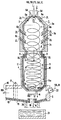
- a primary chamber 3, a secondary chamber 4 and an ash discharge chamber 5 are arranged one behind the other.
- the burner 2 is assigned to the primary chamber 3.
- the primary chamber 3 consists of three partial combustion chambers 3a, 3b and 3c arranged one behind the other.
- the primary chamber 3 can also be in one piece.
- an at least partially combustible material which can be pyrolysis residues PR and smoldering gas SG from a smoldering-firing plant, reaches the primary chamber 3.
- a first air flow EL also reaches the primary chamber 3 via the burner 2
- Primary chamber 3 has inlets 6a, 6b, 6c and 6d distributed over its length for a second air flow ZL called secondary air.
- Each partial combustion chamber 3a, 3b and 3c is assigned at least one inlet 6a, 6b and 6c.
- At least one further inlet 6d can be located in the burner 2.
- a tangential arrangement of at least some of the inlets 6a to d generates vortices in the medium flowing in the primary chamber 3, one of which result in thorough mixing of the medium.
- a weak swirl is also generated in the primary chamber 3 and propagates into the secondary chamber 4.
- the air supply to the primary chamber 3 is dimensioned such that only substoichiometric combustion takes place there.
- the temperature remains below the ash softening point, so that liquid ash A or slag does not arise.
- the primary chamber 3 is connected directly to the secondary chamber 4 via an outlet 8, which can be designed without or with retraction.
- an inlet 9 for a third air flow DL called tertiary air is arranged in the area of the secondary chamber 4 facing the primary chamber 3.
- This air flow DL is dimensioned so that in the secondary chamber 4 there is a complete combustion of the residue R fed from the primary chamber 3. This combustion takes place at a temperature above the ash softening point, so that liquid ash A or slag is formed.
- the inlets 9 for the third air flow DL are also obliquely aligned with the wall of the combustion chamber 1 for the second airflow ZL, that is to say with a tangential component. This creates a swirl in the residue R, which is located in the secondary chamber 4, through which liquid ash A or slag is deposited on the inner surface of the secondary chamber 4. The liquid ash A flows down there.
- the inner walls of the secondary chamber 4 are provided with a layer 10 made of stones or ramming paste. So that less expensive material is sufficient for the layer 10 of the secondary chamber 4, there are cooling channels 11 in the walls of the secondary chamber 4 through which a coolant, in particular water or air, flows.
- the ash discharge space 5 connects to the secondary chamber 4 via a narrow exit 12.
- the liquid ash A or slag passes through an annular groove 13 which surrounds the outlet 12 and is separated from it by an annular bead 14.
- the bead 14 has a minimal height at a certain point compared to a fictitious horizontal plane. A drain point 14a is thereby formed.
- Liquid ash A which flows down the walls of the secondary chamber 4, first collects in the groove 13 and then passes over the bead 14 at its lowest point, namely at the drain point 14a. By collecting the liquid ash A before it is discharged into the ash discharge space 5, a uniform, continuous ash jet is provided. Because the outlet 12 is narrow, flue gas RG reaches the ash discharge chamber 5 at high speed. The initially directed downward flue gas stream is deflected on a floor 15 of the ash discharge chamber 5. The floor 15 acts like a baffle. Ash particles are separated from the flue gas RG.
- the ash discharge space 5 has a flue gas discharge opening 16 through which the flue gas RG is discharged. If necessary, an ash trap 17 is located in front of the flue gas discharge opening 16, which retains further ash particles. To remove the liquid ash A or slag, there is an ash outlet hole 18 in the ash discharge space 5. This ash outlet hole 18 is swept by hot flue gas RG and is thus heated so that ash A or slag cannot solidify in the ash outlet hole 18. The ash outlet hole 18 can therefore not clog.
- the ash discharge space 5 is wider than the outlet 12 of the secondary chamber 4. Therefore, liquid ash A or slag cannot reach the side walls of the ash discharge space 5, which therefore need not be made of a highly resistant material.
- the floor 15 of the ash discharge space 5 is provided with a layer 19 of ramming mass or stones, similar to the walls of the secondary chamber 4, and often contains cooling channels 20.
- Cooling ducts can also be present in the side walls. Due to the cooling, a solid slag layer is formed on the floor 15 of the ash discharge space 5 during the operation of the combustion chamber 1, which layer protects the floor 15 from erosion. On this solid slag layer, which serves as a heat insulation layer, the liquid ash A flows to the ash outlet hole 18 and from there reaches a water container 21, where it granulates. The lowest point of the annular bead 14 around the outlet 12, the outlet point 14a of the secondary chamber 4 is at a position which is the greatest distance from the flue gas discharge opening 16.
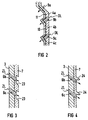
- the combustion chamber in FIG. 2 differs from the combustion chamber 1 in FIG. 1 only in that, in addition to the primary chamber 3, the secondary chamber 4 is also divided into partial combustion chambers 4a, 4b, 4c. Each partial combustion chamber 4a, 4b and 4c is assigned at least one inlet 9a, 9b and 9c. This results in a good mixing of the medium in the secondary chamber 4.
- the weak swirl already generated in the primary chamber 3 is also supported in the secondary chamber 4.
- the air supply and thus the combustion can be controlled well.
- the air inlets 6b, 6c in the primary chamber 3 can, for example, be designed such that the inner wall of the primary chamber 3, as shown in FIG. 3, has indentations 23, the Inlets 6b, 6c open into these indentations 23.
- the inlets 6b, 6c are in a protected position.
- Corresponding indentations for receiving the inlets 9b, 9c can also have the inner wall of the secondary chamber 4.
- a roof-shaped projection 24 can be arranged on the inner wall of the primary chamber 3 above an inlet 6b, 6c for the protection thereof.
- a corresponding roof-shaped projection can also be arranged above an inlet 9b, 9c on the inner wall of the secondary chamber 4.
- fuels in particular pyrolysis residues PR and smoldering gas SG, which originate from a smoldering drum, can be completely burned and converted into flue gas RG and liquid ash A or slag, without the need for complex and expensive coatings on the combustion chamber 1 and without frequent maintenance and repairs to the combustion chamber 1 are necessary.
Landscapes
- Engineering & Computer Science (AREA)
- Mechanical Engineering (AREA)
- General Engineering & Computer Science (AREA)
- Incineration Of Waste (AREA)
- Gasification And Melting Of Waste (AREA)
- Paper (AREA)
- Chemical And Physical Treatments For Wood And The Like (AREA)
- Combustion Methods Of Internal-Combustion Engines (AREA)
- Ceramic Products (AREA)
Applications Claiming Priority (2)
| Application Number | Priority Date | Filing Date | Title |
|---|---|---|---|
| EP89113285 | 1989-07-19 | ||
| EP89113285 | 1989-07-19 |
Publications (2)
| Publication Number | Publication Date |
|---|---|
| EP0409037A1 EP0409037A1 (de) | 1991-01-23 |
| EP0409037B1 true EP0409037B1 (de) | 1994-09-21 |
Family
ID=8201644
Family Applications (1)
| Application Number | Title | Priority Date | Filing Date |
|---|---|---|---|
| EP90113091A Expired - Lifetime EP0409037B1 (de) | 1989-07-19 | 1990-07-09 | Brennkammer zum Verbrennen zumindest teilweise brennbarer Stoffe |
Country Status (11)
| Country | Link |
|---|---|
| US (1) | US5050512A (no) |
| EP (1) | EP0409037B1 (no) |
| JP (1) | JPH0814363B2 (no) |
| AT (1) | ATE112032T1 (no) |
| CA (1) | CA2021344A1 (no) |
| DD (1) | DD296744A5 (no) |
| DE (1) | DE59007204D1 (no) |
| DK (1) | DK0409037T3 (no) |
| ES (1) | ES2059906T3 (no) |
| NO (1) | NO172007C (no) |
| PT (1) | PT94746A (no) |
Families Citing this family (22)
| Publication number | Priority date | Publication date | Assignee | Title |
|---|---|---|---|---|
| DE3724024A1 (de) * | 1987-07-21 | 1989-02-02 | Abus Kg | Seilfuehrung fuer trommeln |
| FR2671606B1 (fr) * | 1991-01-14 | 1993-04-16 | Trepaud | Procede et installation d'incineration de dechets. |
| JPH0772608B2 (ja) * | 1991-06-24 | 1995-08-02 | 株式会社神戸製鋼所 | 廃棄物の燃焼溶融装置 |
| JP2977368B2 (ja) * | 1992-05-01 | 1999-11-15 | 三菱重工業株式会社 | 石炭燃焼器およびそのスラグ排出装置 |
| FR2698156B1 (fr) * | 1992-11-16 | 1995-01-27 | Rhone Poulenc Chimie | Procédé de traitement thermique d'un effluent comprenant des matières organiques polluantes ou un composé inorganique. |
| DE4409951A1 (de) | 1994-03-23 | 1995-09-28 | Abfallwirtschaftsges | Vorrichtung zum Verbrennen von staubförmigen Materialien |
| DE69718020T2 (de) * | 1996-09-04 | 2003-11-06 | Ebara Corp., Tokio/Tokyo | Schmelzdrehrohrofen und verfahren zum vergasen von abfällen in demselben |
| JP4561779B2 (ja) * | 1996-09-04 | 2010-10-13 | 宇部興産株式会社 | 旋回溶融炉及び旋回溶融炉を用いた廃棄物のガス化方法 |
| JPH10103634A (ja) * | 1996-09-25 | 1998-04-21 | Kobe Steel Ltd | 廃棄物処理設備における溶融炉の運転方法及び装置 |
| IT1304328B1 (it) * | 1997-04-22 | 2001-03-15 | Danieli Off Mecc | Procedimento di trattamento fumi e relativo dispositivo |
| WO1999039356A1 (fr) * | 1998-01-30 | 1999-08-05 | Hitachi, Ltd. | Appareil de fusion de matieres solides |
| DE19806823C2 (de) * | 1998-02-18 | 1999-12-09 | Loesche Gmbh | Vorrichtung und Verfahren zur Verbrennung vanadiumhaltiger Brennstoffe |
| AT406901B (de) | 1998-04-17 | 2000-10-25 | Andritz Patentverwaltung | Verfahren und vorrichtung zur verbrennung von partikelförmigen feststoffen |
| TW409172B (en) * | 1999-01-27 | 2000-10-21 | Sumitomo Metal Ind | Waste gasification melting furnace and gasification melting method |
| US6363868B1 (en) * | 1999-08-17 | 2002-04-02 | Independant Stave Co. | Combustors and burners with high turndown ratio |
| US6520098B1 (en) | 2000-09-29 | 2003-02-18 | Tokyo Electric Power Company | Apparatus and method for disposing of dam dirt |
| US6422159B1 (en) * | 2001-05-14 | 2002-07-23 | W. C. Hunter | Incinerator for home use |
| JP5611448B2 (ja) * | 2011-03-18 | 2014-10-22 | 三菱重工環境・化学エンジニアリング株式会社 | 燃焼装置 |
| CN102878550B (zh) * | 2012-10-12 | 2015-04-15 | 浙江大学 | 燃水煤浆液态排渣旋风炉分级配风及再燃低NOx的方法 |
| KR101880160B1 (ko) * | 2016-08-25 | 2018-07-20 | 김병태 | 폐기물 소각용 보일러장치 |
| KR101736838B1 (ko) * | 2017-04-20 | 2017-05-29 | 채재우 | 물과 연소공기의 열분해를 이용한 하이브리드형 연소장치 |
| US11506379B2 (en) * | 2018-05-07 | 2022-11-22 | Victor DE AVILA RUEDA | Catalytic oxidizer |
Family Cites Families (22)
| Publication number | Priority date | Publication date | Assignee | Title |
|---|---|---|---|---|
| GB616840A (en) * | 1945-08-21 | 1949-01-27 | Int Comb Ltd | Method of and apparatus for burning finely divided or pulverized fuel at very high rates of heat liberation |
| US2516141A (en) * | 1949-07-01 | 1950-07-25 | Louis L Newman | Apparatus and method for gasifying carbonaceous material |
| US2707444A (en) * | 1949-09-15 | 1955-05-03 | Directie Staatsmijnen Nl | Cyclone furnace |
| US2717563A (en) * | 1950-01-16 | 1955-09-13 | Babcock & Wilcox Co | Horizontal cyclone furnace |
| FR1043461A (fr) * | 1950-10-05 | 1953-11-09 | Steinkohlen Elek Zitat A G | Foyer à combustible pulvérisé et gazogène pour combustibles de toutes sortes et de toutes granulations, présentant un haut degré de retenue des cendres |
| JPS4934983A (no) * | 1972-08-05 | 1974-03-30 | ||
| JPS50103868A (no) * | 1974-01-29 | 1975-08-16 | ||
| CH622082A5 (no) * | 1977-04-06 | 1981-03-13 | Von Roll Ag | |
| JPS55105111A (en) * | 1979-02-08 | 1980-08-12 | Nittetsu Kakoki Kk | Process for combustion of fluid |
| US4291634A (en) * | 1980-05-29 | 1981-09-29 | Union Carbide Corporation | Solid refuse disposal apparatus |
| JPS5819619A (ja) * | 1981-07-28 | 1983-02-04 | Daido Steel Co Ltd | 廃棄物溶融処理炉 |
| JPS59205509A (ja) * | 1983-05-09 | 1984-11-21 | Nippon Furnace Kogyo Kaisha Ltd | スラグタツプ式サイクロン燃焼炉 |
| JPS605224U (ja) * | 1983-06-24 | 1985-01-16 | 住友電気工業株式会社 | 一体化電線結合器 |
| EP0143510A1 (en) * | 1983-08-08 | 1985-06-05 | Inc. Aqua-Chem | Bio-mass suspension burner |
| US4512267A (en) * | 1984-01-24 | 1985-04-23 | John Zink Company | Methods and apparatus for combusting ash producing solids |
| JPS60178209A (ja) * | 1984-02-24 | 1985-09-12 | ストウ−デイセントラム・ヴオア・カ−ネエナギ− | 物質混合物処理方法及び装置 |
| DE3527697C2 (de) * | 1985-08-02 | 1994-08-04 | Babcock Energie Umwelt | Verfahren zum Verbrennen von Kohle |
| US4745869A (en) * | 1987-06-22 | 1988-05-24 | Westinghouse Electric Corp. | Method and apparatus for calcining limestone using coal combustion for heating |
| US4873930A (en) * | 1987-07-30 | 1989-10-17 | Trw Inc. | Sulfur removal by sorbent injection in secondary combustion zones |
| DE3811820A1 (de) * | 1987-08-03 | 1989-02-16 | Siemens Ag | Verfahren und anlage zur thermischen abfallentsorgung |
| DE8811665U1 (de) * | 1988-09-14 | 1988-11-03 | Siemens AG, 1000 Berlin und 8000 München | Wärmetauscher für den Heizkreislauf einer Pyrolysetrommel |
| US4920898A (en) * | 1988-09-15 | 1990-05-01 | Trw Inc. | Gas turbine slagging combustion system |
-
1990
- 1990-07-09 AT AT90113091T patent/ATE112032T1/de not_active IP Right Cessation
- 1990-07-09 EP EP90113091A patent/EP0409037B1/de not_active Expired - Lifetime
- 1990-07-09 ES ES90113091T patent/ES2059906T3/es not_active Expired - Lifetime
- 1990-07-09 DE DE59007204T patent/DE59007204D1/de not_active Expired - Lifetime
- 1990-07-09 DK DK90113091.4T patent/DK0409037T3/da active
- 1990-07-16 US US07/552,812 patent/US5050512A/en not_active Expired - Lifetime
- 1990-07-16 JP JP2189280A patent/JPH0814363B2/ja not_active Expired - Lifetime
- 1990-07-17 DD DD90342853A patent/DD296744A5/de not_active IP Right Cessation
- 1990-07-17 CA CA002021344A patent/CA2021344A1/en not_active Abandoned
- 1990-07-17 NO NO903201A patent/NO172007C/no unknown
- 1990-07-18 PT PT94746A patent/PT94746A/pt not_active Application Discontinuation
Also Published As
| Publication number | Publication date |
|---|---|
| CA2021344A1 (en) | 1991-01-20 |
| NO903201L (no) | 1991-01-21 |
| ES2059906T3 (es) | 1994-11-16 |
| JPH0363407A (ja) | 1991-03-19 |
| NO172007B (no) | 1993-02-15 |
| ATE112032T1 (de) | 1994-10-15 |
| NO903201D0 (no) | 1990-07-17 |
| US5050512A (en) | 1991-09-24 |
| DD296744A5 (de) | 1991-12-12 |
| DK0409037T3 (da) | 1995-02-20 |
| DE59007204D1 (de) | 1994-10-27 |
| EP0409037A1 (de) | 1991-01-23 |
| NO172007C (no) | 1993-05-26 |
| PT94746A (pt) | 1992-02-28 |
| JPH0814363B2 (ja) | 1996-02-14 |
Similar Documents
| Publication | Publication Date | Title |
|---|---|---|
| EP0409037B1 (de) | Brennkammer zum Verbrennen zumindest teilweise brennbarer Stoffe | |
| DE2735139C2 (de) | Verbrennungsofen für Abfälle | |
| DE69002605T2 (de) | System für die Behandlung von Müll in geschmolzenem Zustand. | |
| EP0767342B2 (de) | Verfahren zur thermischen Entsorgung von losem Müll | |
| EP0413799B1 (de) | Mehrstufige rostanordnung zum verbrennen von müll und abfall sowie verfahren zu deren betrieb | |
| EP0862019A1 (de) | Verfahren und Vorrichtung zur thermischen Behandlung von Flugstäuben aus Rostverbrennungsanlagen | |
| EP0007977A1 (de) | Verfahren zum Brennen von stückigem Brenngut sowie Ringschachtofen zu seiner Durchführung | |
| EP0908217A1 (de) | Verfahren zur Behandlung von Rauchgas | |
| EP1052231A1 (de) | Verfahren und Anlage zur thermischen Behandlung von mehlförmigen Rohmaterialien | |
| DE1771299B1 (de) | Anlage zum Schmelzen von Glas | |
| EP0303963A2 (de) | Verfahren und Anlage zur Calcinierung von Kalkstein | |
| EP1477734B1 (de) | Heizeinrichtung | |
| DE1301868B (de) | Schachtfeuerung zur Muellverbrennung | |
| DE69513461T2 (de) | Kohlenverbrennungsvorrichtung | |
| EP0815394B2 (de) | Verbrennungsanlage | |
| WO1982000331A1 (fr) | Generateur de gaz chaud | |
| DE1246924B (de) | Muellverbrennungsanlage mit Schmelzkammer | |
| DE4202895C2 (de) | Vorrichtung zum Verbrennen kohlenstoffhaltiger Brennstoffe in einer zirkulierenden Wirbelschicht | |
| DE4442126C1 (de) | Düsenboden für eine Wirbelschichtfeuerung | |
| DE8913457U1 (de) | Rostanordnung zum Verbrennen von Müll und Abfall | |
| DE8902692U1 (de) | Rostanordnung zum Verbrennen von Müll und Abfall | |
| DE3149549A1 (de) | "brenner fuer einen feststoffpartikel enthaltenden brennstoff" | |
| DE2345585C3 (de) | Verfahren und Vorrichtung zur Schmelzverbrennung von Abfallstoffen | |
| DE20207468U1 (de) | Asphalterhitzer mit Abgas-Wärmerückführung | |
| WO1997042450A1 (de) | Verbrennungsanlage zur erzeugung von energie und verfahren zum betreiben der verbrennungsanlage |
Legal Events
| Date | Code | Title | Description |
|---|---|---|---|
| PUAI | Public reference made under article 153(3) epc to a published international application that has entered the european phase |
Free format text: ORIGINAL CODE: 0009012 |
|
| AK | Designated contracting states |
Kind code of ref document: A1 Designated state(s): AT BE CH DE DK ES FR GB GR IT LI LU NL SE |
|
| 17P | Request for examination filed |
Effective date: 19901220 |
|
| 17Q | First examination report despatched |
Effective date: 19920325 |
|
| GRAA | (expected) grant |
Free format text: ORIGINAL CODE: 0009210 |
|
| AK | Designated contracting states |
Kind code of ref document: B1 Designated state(s): AT BE CH DE DK ES FR GB GR IT LI LU NL SE |
|
| PG25 | Lapsed in a contracting state [announced via postgrant information from national office to epo] |
Ref country code: GR Free format text: LAPSE BECAUSE OF FAILURE TO SUBMIT A TRANSLATION OF THE DESCRIPTION OR TO PAY THE FEE WITHIN THE PRESCRIBED TIME-LIMIT Effective date: 19940921 |
|
| REF | Corresponds to: |
Ref document number: 112032 Country of ref document: AT Date of ref document: 19941015 Kind code of ref document: T |
|
| REF | Corresponds to: |
Ref document number: 59007204 Country of ref document: DE Date of ref document: 19941027 |
|
| REG | Reference to a national code |
Ref country code: ES Ref legal event code: FG2A Ref document number: 2059906 Country of ref document: ES Kind code of ref document: T3 |
|
| ITF | It: translation for a ep patent filed | ||
| GBT | Gb: translation of ep patent filed (gb section 77(6)(a)/1977) |
Effective date: 19941222 |
|
| ET | Fr: translation filed | ||
| EAL | Se: european patent in force in sweden |
Ref document number: 90113091.4 |
|
| REG | Reference to a national code |
Ref country code: DK Ref legal event code: T3 |
|
| PLBE | No opposition filed within time limit |
Free format text: ORIGINAL CODE: 0009261 |
|
| STAA | Information on the status of an ep patent application or granted ep patent |
Free format text: STATUS: NO OPPOSITION FILED WITHIN TIME LIMIT |
|
| 26N | No opposition filed | ||
| REG | Reference to a national code |
Ref country code: GB Ref legal event code: IF02 |
|
| PGFP | Annual fee paid to national office [announced via postgrant information from national office to epo] |
Ref country code: AT Payment date: 20050615 Year of fee payment: 16 |
|
| PGFP | Annual fee paid to national office [announced via postgrant information from national office to epo] |
Ref country code: NL Payment date: 20050705 Year of fee payment: 16 |
|
| PGFP | Annual fee paid to national office [announced via postgrant information from national office to epo] |
Ref country code: SE Payment date: 20050707 Year of fee payment: 16 |
|
| PGFP | Annual fee paid to national office [announced via postgrant information from national office to epo] |
Ref country code: DK Payment date: 20050711 Year of fee payment: 16 |
|
| PGFP | Annual fee paid to national office [announced via postgrant information from national office to epo] |
Ref country code: ES Payment date: 20050713 Year of fee payment: 16 Ref country code: LU Payment date: 20050713 Year of fee payment: 16 |
|
| PGFP | Annual fee paid to national office [announced via postgrant information from national office to epo] |
Ref country code: BE Payment date: 20050722 Year of fee payment: 16 |
|
| PGFP | Annual fee paid to national office [announced via postgrant information from national office to epo] |
Ref country code: CH Payment date: 20051013 Year of fee payment: 16 |
|
| PG25 | Lapsed in a contracting state [announced via postgrant information from national office to epo] |
Ref country code: AT Free format text: LAPSE BECAUSE OF NON-PAYMENT OF DUE FEES Effective date: 20060709 |
|
| PG25 | Lapsed in a contracting state [announced via postgrant information from national office to epo] |
Ref country code: SE Free format text: LAPSE BECAUSE OF NON-PAYMENT OF DUE FEES Effective date: 20060710 |
|
| PG25 | Lapsed in a contracting state [announced via postgrant information from national office to epo] |
Ref country code: BE Free format text: LAPSE BECAUSE OF NON-PAYMENT OF DUE FEES Effective date: 20060731 Ref country code: DK Free format text: LAPSE BECAUSE OF NON-PAYMENT OF DUE FEES Effective date: 20060731 Ref country code: CH Free format text: LAPSE BECAUSE OF NON-PAYMENT OF DUE FEES Effective date: 20060731 Ref country code: LI Free format text: LAPSE BECAUSE OF NON-PAYMENT OF DUE FEES Effective date: 20060731 |
|
| REG | Reference to a national code |
Ref country code: CH Ref legal event code: PUE Owner name: MITSUI ENGINEERING & SHIPBUILDING CO., LTD. Free format text: SIEMENS AKTIENGESELLSCHAFT#WITTELSBACHERPLATZ 2#D-80333 MUENCHEN (DE) -TRANSFER TO- MITSUI ENGINEERING & SHIPBUILDING CO., LTD.#64, TSUKIJI 5-CHOME, CHUO-KU#TOKYO 104-8439 (JP) $ TAKUMA CO., LTD.#1-3-23 DOJIMAHAMA , KITA -KU#OSAKA 530-004 (JP) |
|
| REG | Reference to a national code |
Ref country code: GB Ref legal event code: 732E |
|
| REG | Reference to a national code |
Ref country code: FR Ref legal event code: TP |
|
| PG25 | Lapsed in a contracting state [announced via postgrant information from national office to epo] |
Ref country code: NL Free format text: LAPSE BECAUSE OF NON-PAYMENT OF DUE FEES Effective date: 20070201 |
|
| REG | Reference to a national code |
Ref country code: DK Ref legal event code: EBP |
|
| REG | Reference to a national code |
Ref country code: CH Ref legal event code: PL |
|
| EUG | Se: european patent has lapsed | ||
| NLV4 | Nl: lapsed or anulled due to non-payment of the annual fee |
Effective date: 20070201 |
|
| REG | Reference to a national code |
Ref country code: ES Ref legal event code: FD2A Effective date: 20060710 |
|
| BERE | Be: lapsed |
Owner name: *SIEMENS A.G. Effective date: 20060731 |
|
| PG25 | Lapsed in a contracting state [announced via postgrant information from national office to epo] |
Ref country code: ES Free format text: LAPSE BECAUSE OF NON-PAYMENT OF DUE FEES Effective date: 20060710 |
|
| PG25 | Lapsed in a contracting state [announced via postgrant information from national office to epo] |
Ref country code: LU Free format text: LAPSE BECAUSE OF NON-PAYMENT OF DUE FEES Effective date: 20060709 |
|
| PGFP | Annual fee paid to national office [announced via postgrant information from national office to epo] |
Ref country code: FR Payment date: 20090702 Year of fee payment: 20 |
|
| PGFP | Annual fee paid to national office [announced via postgrant information from national office to epo] |
Ref country code: DE Payment date: 20090909 Year of fee payment: 20 Ref country code: GB Payment date: 20090710 Year of fee payment: 20 |
|
| PGFP | Annual fee paid to national office [announced via postgrant information from national office to epo] |
Ref country code: IT Payment date: 20090729 Year of fee payment: 20 |
|
| REG | Reference to a national code |
Ref country code: GB Ref legal event code: PE20 Expiry date: 20100708 |
|
| PG25 | Lapsed in a contracting state [announced via postgrant information from national office to epo] |
Ref country code: GB Free format text: LAPSE BECAUSE OF EXPIRATION OF PROTECTION Effective date: 20100708 |
|
| PG25 | Lapsed in a contracting state [announced via postgrant information from national office to epo] |
Ref country code: DE Free format text: LAPSE BECAUSE OF EXPIRATION OF PROTECTION Effective date: 20100709 |