EP0409037B1 - Combustion chamber for the combustion of at least partially combustible materials - Google Patents
Combustion chamber for the combustion of at least partially combustible materials Download PDFInfo
- Publication number
- EP0409037B1 EP0409037B1 EP90113091A EP90113091A EP0409037B1 EP 0409037 B1 EP0409037 B1 EP 0409037B1 EP 90113091 A EP90113091 A EP 90113091A EP 90113091 A EP90113091 A EP 90113091A EP 0409037 B1 EP0409037 B1 EP 0409037B1
- Authority
- EP
- European Patent Office
- Prior art keywords
- chamber
- combustion chamber
- combustion
- ash
- primary
- Prior art date
- Legal status (The legal status is an assumption and is not a legal conclusion. Google has not performed a legal analysis and makes no representation as to the accuracy of the status listed.)
- Expired - Lifetime
Links
- 238000002485 combustion reaction Methods 0.000 title claims abstract description 123
- 239000000463 material Substances 0.000 title claims abstract description 26
- 239000003546 flue gas Substances 0.000 claims abstract description 39
- UGFAIRIUMAVXCW-UHFFFAOYSA-N Carbon monoxide Chemical compound [O+]#[C-] UGFAIRIUMAVXCW-UHFFFAOYSA-N 0.000 claims abstract description 38
- 238000000197 pyrolysis Methods 0.000 claims abstract description 24
- 239000007789 gas Substances 0.000 claims abstract description 22
- 239000000126 substance Substances 0.000 claims abstract description 10
- 239000012530 fluid Substances 0.000 claims abstract 3
- 238000001816 cooling Methods 0.000 claims description 15
- XLYOFNOQVPJJNP-UHFFFAOYSA-N water Substances O XLYOFNOQVPJJNP-UHFFFAOYSA-N 0.000 claims description 7
- 238000007373 indentation Methods 0.000 claims description 6
- 239000011324 bead Substances 0.000 claims description 5
- 239000011449 brick Substances 0.000 claims description 5
- 239000002826 coolant Substances 0.000 claims description 5
- 239000002699 waste material Substances 0.000 claims description 5
- 238000007599 discharging Methods 0.000 claims description 3
- 239000002956 ash Substances 0.000 claims 14
- 239000004927 clay Substances 0.000 claims 2
- 230000004907 flux Effects 0.000 claims 2
- 239000010881 fly ash Substances 0.000 claims 2
- 238000003763 carbonization Methods 0.000 abstract description 15
- 230000015572 biosynthetic process Effects 0.000 abstract description 2
- 238000000034 method Methods 0.000 abstract description 2
- 239000010813 municipal solid waste Substances 0.000 abstract 2
- 239000002893 slag Substances 0.000 description 50
- 239000007788 liquid Substances 0.000 description 43
- 238000000576 coating method Methods 0.000 description 7
- 239000000428 dust Substances 0.000 description 7
- 239000011248 coating agent Substances 0.000 description 6
- 239000000446 fuel Substances 0.000 description 5
- 238000010438 heat treatment Methods 0.000 description 5
- 238000012423 maintenance Methods 0.000 description 5
- 230000008439 repair process Effects 0.000 description 5
- 239000007787 solid Substances 0.000 description 5
- 150000001875 compounds Chemical class 0.000 description 4
- 238000002156 mixing Methods 0.000 description 4
- 239000002245 particle Substances 0.000 description 4
- 239000008187 granular material Substances 0.000 description 3
- 239000002028 Biomass Substances 0.000 description 2
- 230000003628 erosive effect Effects 0.000 description 2
- 230000006735 deficit Effects 0.000 description 1
- 230000000694 effects Effects 0.000 description 1
- 238000010304 firing Methods 0.000 description 1
- 239000003500 flue dust Substances 0.000 description 1
- 238000009413 insulation Methods 0.000 description 1
- 238000004519 manufacturing process Methods 0.000 description 1
- 238000013021 overheating Methods 0.000 description 1
- 230000002028 premature Effects 0.000 description 1
- 238000000926 separation method Methods 0.000 description 1
- 238000007711 solidification Methods 0.000 description 1
- 230000008023 solidification Effects 0.000 description 1
Images
Classifications
-
- F—MECHANICAL ENGINEERING; LIGHTING; HEATING; WEAPONS; BLASTING
- F23—COMBUSTION APPARATUS; COMBUSTION PROCESSES
- F23G—CREMATION FURNACES; CONSUMING WASTE PRODUCTS BY COMBUSTION
- F23G5/00—Incineration of waste; Incinerator constructions; Details, accessories or control therefor
- F23G5/32—Incineration of waste; Incinerator constructions; Details, accessories or control therefor the waste being subjected to a whirling movement, e.g. cyclonic incinerators
-
- F—MECHANICAL ENGINEERING; LIGHTING; HEATING; WEAPONS; BLASTING
- F23—COMBUSTION APPARATUS; COMBUSTION PROCESSES
- F23G—CREMATION FURNACES; CONSUMING WASTE PRODUCTS BY COMBUSTION
- F23G5/00—Incineration of waste; Incinerator constructions; Details, accessories or control therefor
- F23G5/02—Incineration of waste; Incinerator constructions; Details, accessories or control therefor with pretreatment
- F23G5/027—Incineration of waste; Incinerator constructions; Details, accessories or control therefor with pretreatment pyrolising or gasifying stage
-
- F—MECHANICAL ENGINEERING; LIGHTING; HEATING; WEAPONS; BLASTING
- F23—COMBUSTION APPARATUS; COMBUSTION PROCESSES
- F23G—CREMATION FURNACES; CONSUMING WASTE PRODUCTS BY COMBUSTION
- F23G5/00—Incineration of waste; Incinerator constructions; Details, accessories or control therefor
- F23G5/08—Incineration of waste; Incinerator constructions; Details, accessories or control therefor having supplementary heating
- F23G5/14—Incineration of waste; Incinerator constructions; Details, accessories or control therefor having supplementary heating including secondary combustion
- F23G5/16—Incineration of waste; Incinerator constructions; Details, accessories or control therefor having supplementary heating including secondary combustion in a separate combustion chamber
- F23G5/165—Incineration of waste; Incinerator constructions; Details, accessories or control therefor having supplementary heating including secondary combustion in a separate combustion chamber arranged at a different level
-
- F—MECHANICAL ENGINEERING; LIGHTING; HEATING; WEAPONS; BLASTING
- F23—COMBUSTION APPARATUS; COMBUSTION PROCESSES
- F23J—REMOVAL OR TREATMENT OF COMBUSTION PRODUCTS OR COMBUSTION RESIDUES; FLUES
- F23J1/00—Removing ash, clinker, or slag from combustion chambers
- F23J1/08—Liquid slag removal
-
- F—MECHANICAL ENGINEERING; LIGHTING; HEATING; WEAPONS; BLASTING
- F23—COMBUSTION APPARATUS; COMBUSTION PROCESSES
- F23J—REMOVAL OR TREATMENT OF COMBUSTION PRODUCTS OR COMBUSTION RESIDUES; FLUES
- F23J9/00—Preventing premature solidification of molten combustion residues
-
- F—MECHANICAL ENGINEERING; LIGHTING; HEATING; WEAPONS; BLASTING
- F23—COMBUSTION APPARATUS; COMBUSTION PROCESSES
- F23G—CREMATION FURNACES; CONSUMING WASTE PRODUCTS BY COMBUSTION
- F23G2201/00—Pretreatment
- F23G2201/30—Pyrolysing
- F23G2201/303—Burning pyrogases
-
- F—MECHANICAL ENGINEERING; LIGHTING; HEATING; WEAPONS; BLASTING
- F23—COMBUSTION APPARATUS; COMBUSTION PROCESSES
- F23G—CREMATION FURNACES; CONSUMING WASTE PRODUCTS BY COMBUSTION
- F23G2201/00—Pretreatment
- F23G2201/30—Pyrolysing
- F23G2201/304—Burning pyrosolids
Definitions
- the invention relates to a combustion chamber which is equipped with a burner and has an inlet for a product which comprises pyrolysis residue and carbonization gas from a pyrolysis reactor which converts waste into carbonization gas and essentially nonvolatile pyrolysis residue, the pyrolysis reactor in particular being a discharge device for the nonvolatile Pyrolysis residue is connected, which has a carbonization gas outlet for discharging carbonization gas, and wherein the carbonization gas and processed pyrolysis residue are fed to the combustion chamber.
- a burner for biomass is known from EP 0 143 510 A1, into which combustion air is fed in at four different points.
- the supplied biomass is moist and is dried and degassed in the burner.
- the known burner has a combustion chamber, the entire inner surface of which is provided with a refractory coating.
- a refractory coating In such combustion chambers, it is customary to have a brick lining with refractory refractory bricks. Coating with a refractory so-called ramming compound is also common.
- a system for thermal waste disposal is known from EP 0 302 510 A1.
- This system turns waste into one Pyrolysis reactor converted into carbonization gas and essentially non-volatile pyrolysis residue.
- a discharge device for the non-volatile pyrolysis residue is connected to the pyrolysis reactor and has a carbonization gas outlet connection for discharging carbonization gas.
- the carbonization gas and prepared, for example ground pyrolysis residue enter a combustion chamber.
- a combustion takes place there, producing molten slag.
- Flue gas is also generated, which is discharged from the combustion chamber via a flue gas line.
- the molten slag is also discharged from the combustion chamber. After cooling, it is then in a glazed form.
- the combustion chamber of this system like other known combustion chambers, is lined with firebricks or ramming paste. As with other combustion chambers, an expensive lining is provided so that the operating interval between two necessary maintenance of the combustion chamber is as large as possible.
- the invention has for its object to provide a combustion chamber that is inexpensive to build and yet only rarely requires maintenance.
- the inner lining of the combustion chamber should be inexpensive to manufacture and ensure a long, undisturbed operating time.
- the combustion chamber is at least in three parts, a primary chamber, a secondary chamber and an ash discharge space being arranged one behind the other in that the burner is assigned to the primary chamber, a first air flow (primary air) into the primary chamber via the burner arrives that the primary chamber has an inlet for a second air stream (secondary air) for the substoichiometric combustion of the material at a temperature below the ash softening point and has no slag flow, the walls of the primary chamber not being coated with a material resistant to liquid slag, and the secondary chamber having an inlet for a third air stream (tertiary air) for short-term, intensive, complete combustion of the discharge from the primary chamber with slag flow, the walls of the secondary chamber being coated with a material resistant to liquid slag.
- a first air flow into the primary chamber via the burner arrives that the primary chamber has an inlet for a second air stream (secondary air) for the substoichiometric combustion of the material at a temperature below the ash softening point
- the ash discharge area has, for example, a floor in which there is an ash outlet hole.
- the ash discharge space has, for example, a flue gas discharge opening.
- the primary chamber is designed for substoichiometric combustion. That the combustion always remains substoichiometric, there must always be an air deficit in the primary chamber. Inlets for two separate air flows, the primary air and the secondary air, in the primary chamber can always provide the required air flow at any point in the primary chamber without too much air being present in part of the primary chamber, for example in the upper region. Due to the substoichiometric combustion, the temperature in the primary chamber does not exceed the ash softening point.
- the ash softening point of a certain ash is a temperature at which, by definition, a certain deformation and adhesiveness occurs. Since the ash softening point in the primary chamber is not exceeded, no liquid ash or slag can get to the inner lining of the primary chamber. It is therefore not necessary to line the primary chamber with expensive refractory refractory bricks or with suitable ramming paste.
- the secondary chamber adjoining the primary chamber has an inlet for tertiary air.
- This tertiary air creates an excess of air in the secondary chamber set, which ensures short-term, intensive and complete combustion.
- the temperature exceeds the ash flow point and a slag flow occurs on the inner surface of the secondary chamber.
- the ash flow point of a particular ash is a temperature at which the toughness is so low that the ash flows.
- the secondary chamber is therefore coated with heat-resistant and liquid slag-resistant material according to the invention. This material is more expensive than the material used to coat the primary chamber.
- the system according to the invention only requires the expensive material to coat a part of the combustion chamber, namely the secondary chamber. You can get by with less expensive material.
- the ash discharge chamber is connected to the secondary chamber. There is an ash outlet hole in the bottom. Only the floor of the ash discharge area that comes into contact with liquid ash or slag is coated with material that is resistant to liquid slag.
- the ash discharge chamber has a flue gas discharge opening, to which a flue gas duct leading to a chimney can be connected.
- combustion chamber according to the invention When the combustion chamber according to the invention is used in a plant for thermal waste disposal, a so-called smoldering plant, pyrolysis residue processed in the combustion chamber is burned together with smoldering gas. This leaves flue gas and liquid ash or slag, which can be further processed to melt granulate in a water bath.
- the advantage is achieved that a large part of the combustion chamber, the primary chamber, manages without an expensive lining. Only a small part of the combustion chamber, the secondary chamber requires a lining that is resistant to liquid slag.
- the combustion chamber according to the invention can be carried out inexpensively and ensures a long, undisturbed operating time.
- the walls of the secondary chamber are cooled.
- an expensive coating of the interior of the secondary chamber to protect against liquid ash and slag can also be dispensed with.
- With an inexpensive coating a long, undisturbed operating time is guaranteed.
- a coating can be chosen which is less expensive than a coating which would be necessary in an uncooled chamber in which liquid ash or slag flows.
- the inlet for the second air stream is, for example, in the burner.
- the inlet for the secondary air is located on the upper section of the primary chamber to the side next to the connection for the burner.
- Another example provides that several inlets for secondary air are arranged on the primary chamber distributed over its entire length. In particular, this has the advantage that the air concentration must be set everywhere in the entire primary chamber, which ensures substoichiometric combustion at a temperature below the ash softening point.
- the air supply to the primary chamber should be selected so that on the one hand the temperature of the ash softening point is not exceeded and on the other hand the substoichiometric combustion in the entire primary chamber must always be maintained. This is ensured by the fact that in addition to the primary air, secondary air, particularly at the specially selected points, can get into the primary chamber.
- the air flow can be optimally adjusted at every point in the primary chamber.
- one or more inlets for the secondary air in the primary chamber are oriented obliquely, that is to say with a tangential component, to the wall of the primary chamber. This creates a vortex in the medium in the primary chamber, which continues from the primary chamber into the secondary chamber.
- This supply of secondary air mixes the medium in the primary chamber.
- the weak swirl that arises at the entrance of the secondary chamber favors the formation of a swirl in the secondary chamber.
- inlets for the secondary air in the primary chamber are arranged one below the other in parallel planes.
- two or more inlets for the tertiary air can also be arranged in the secondary chamber in parallel planes.
- the inlets for air can open into indentations which are arranged in the inner wall of the primary chamber and / or the secondary chamber. This protects the outlets from the material in the combustion chamber.
- a roof-shaped projection which is arranged, for example, above an inlet on the inner wall of the combustion chamber, can also serve to protect an opening.
- the primary chamber is divided into partial combustion chambers connected in series.
- Inlets for the second air flow are, for example, in each partial combustion chamber, in its upper section, that is, in the direction of flow at the entrance of the partial combustion chamber.
- the inlet for tertiary air into the secondary chamber is inclined, that is, aligned with a tangential component to the wall of the secondary chamber.
- This will directly in the Secondary chamber creates a swirl that pushes the heavy parts of the medium in the secondary chamber towards the wall.
- liquid ash is deposited on the wall and flows along the wall to the outlet opening of the secondary chamber. From there, the liquid ash arrives in the ash discharge area.
- the effect of the swirl generated in the secondary chamber is significantly improved if a swirl has already been generated in the primary chamber.
- the secondary chamber can also be divided into partial combustion chambers connected in series. Correspondingly there are inlets for the third air flow, for example in each partial combustion chamber of the secondary chamber in its upper section, that is to say in the flow direction at the entrance of the partial combustion chamber.
- the walls of the secondary chamber are covered with stones, for example, from the inside. These stones are made of a material that is resistant and is not attacked by slag and ash. According to a further example, the walls of the secondary chamber are coated from the inside with a ramming compound that has the appropriate properties. Since only the secondary chamber is to be equipped with high-quality stones or ramming compounds, this results in a cost advantage compared to a combustion chamber, which must be lined entirely with high-quality stones or ramming compounds.
- the walls In order to make the walls of the secondary chamber even cheaper, these walls are cooled. To do this, the walls contain the secondary Chamber, for example, cooling channels that hold a coolant, especially water or air. This constant cooling of the secondary chamber walls from the outside prevents excessive overheating of the inner surfaces of the walls wetted with the liquid ash or slag. As a result, inexpensive liners can be used even in the secondary chamber, as in the primary chamber. As a result of the cooling, a thin, firm layer of slag forms on the surface of the lining, on which a liquid slag film forms on the inside. The solid slag layer protects the lining material underneath from being attacked by the liquid slag. So you do not need an expensive material resistant to slag flow for the lining of the secondary chamber.
- the secondary Chamber for example, cooling channels that hold a coolant, especially water or air.
- Airborne dust for example, can be fed to the primary chamber or the secondary chamber or the ash discharge chamber.
- the supply can take place via special supply openings, but also through the burner or together with secondary air or tertiary air. If the dust can be easily incorporated into a slag bath due to its properties, then it is particularly advantageous to feed the dust directly to the ash discharge area. In this way, the flying dust is incorporated into the slag.
- the ash discharge space is, for example, wider than the exit of the secondary chamber.
- the slag or liquid ash carried out of the secondary chamber does not reach the side walls of the ash discharge space. Therefore, only the floor of the ash discharge area must be covered with material that is resistant to liquid slag.
- This can be expensive stones or ramming masses, or also inexpensive stones or ramming masses, if a cooling device is available in the floor of the ash discharge chamber.
- the cooling device can be constructed such that the bottom of the ash discharge space cooling channels contains, for receiving a coolant, especially water or air.
- the floor of the ash discharge area runs e.g. horizontal, which, when cooled, can form a layer of slag around the ash outlet hole that protects the floor from erosion.
- the exit of the secondary chamber is surrounded, for example, in the secondary chamber by a ring which has a drainage point on a side facing away from the flue gas discharge opening.
- a ring which has a drainage point on a side facing away from the flue gas discharge opening.
- the height of this ring at a point facing away from the flue gas discharge nozzle of the ash discharge space is smaller than usual. This results in a channel that runs around the exit of the secondary chamber. When the combustion chamber is operating, this channel fills with liquid ash or slag. Where the ring is the lowest in relation to a horizontal plane, the slag and the channel are filled in a jet from the secondary chamber into the ash discharge area.
- the ring Since the lowest point of the ring is located at a point facing away from the flue gas discharge nozzle of the ash discharge area, the entire liquid slag flows into the ash discharge area with only one jet.
- the ring therefore has the advantage that there is only one ash jet from the secondary chamber into the ash discharge space, which is not crossed by the flue gas flowing out. The ash flow is therefore not disturbed by the flue gas flow. If both liquid ash and flue gas flow out of the wide exit of the secondary chamber in an uncontrolled manner, flue gas and slag could be mixed in the ash discharge chamber. Instead of getting to the ash outlet hole, small pieces of slag would be carried away with the flue gas. This is prevented by the ring in the secondary chamber.
- An ash trap for example, is arranged in the flue gas discharge nozzle of the ash discharge space. This has the advantage that fewer ash particles get into the flue gas duct. Such particles would contaminate existing heat exchanger heating surfaces in the flue gas line.
- a heating burner is arranged in the ash discharge area. It is used if the liquid slag or ash coming from the secondary chamber should have poor flow properties. Then the slag in the ash discharge space is heated again so that it reaches the ash outlet hole and exits there. If the slag or ash flows sufficiently, the heating burner remains switched off.
- the heating burner is fed with an external fuel. However, it can also be fed with carbonization gas that originates from a pyrolysis reactor. This saves external fuel.
- the combustion chamber according to the invention has the particular advantage that long operating intervals can be carried out without maintenance or repair work on the combustion chamber if the combustion chamber is inexpensive.
- a swirl is generated in the material to be treated, but especially in the residue of the substoichiometric combustion, as a result of which the liquid ash which is formed is carried outside and against a container wall, e.g. the combustion chamber wall. This improves the separation of flue gas and liquid ash.
- the material to be treated or the residue of the substoichiometric combustion is admixed, for example, with airborne dust which can originate from the device of the invention and which is thus returned. Dust can also fly be mixed with the still flowing ash or slag. The flight dust is thus advantageously wholly or partly incorporated into later solid slag granules.
- the liquid ash after it has been formed, is heated again to prevent premature solidification.
- the slag then flows better out of the ash discharge chamber of the combustion chamber.
- the resulting flue gas can be cooled in a heat exchanger in the burner or in separate feed points e.g. are fed into the combustion chamber together with the combustion air. This means that the required temperature can be set at every point in the combustion chamber.
- the advantage is achieved that the material to be treated, which is in particular pyrolysis residue and carbonization gas from a carbonization process, in a cost-effective combustion chamber that requires little maintenance and repair, reliably in liquid ash and Flue gas is to be dismantled.
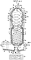
- a primary chamber 3, a secondary chamber 4 and an ash discharge chamber 5 are arranged one behind the other.
- the burner 2 is assigned to the primary chamber 3.
- the primary chamber 3 consists of three partial combustion chambers 3a, 3b and 3c arranged one behind the other.
- the primary chamber 3 can also be in one piece.
- an at least partially combustible material which can be pyrolysis residues PR and smoldering gas SG from a smoldering-firing plant, reaches the primary chamber 3.
- a first air flow EL also reaches the primary chamber 3 via the burner 2
- Primary chamber 3 has inlets 6a, 6b, 6c and 6d distributed over its length for a second air flow ZL called secondary air.
- Each partial combustion chamber 3a, 3b and 3c is assigned at least one inlet 6a, 6b and 6c.
- At least one further inlet 6d can be located in the burner 2.
- a tangential arrangement of at least some of the inlets 6a to d generates vortices in the medium flowing in the primary chamber 3, one of which result in thorough mixing of the medium.
- a weak swirl is also generated in the primary chamber 3 and propagates into the secondary chamber 4.
- the air supply to the primary chamber 3 is dimensioned such that only substoichiometric combustion takes place there.
- the temperature remains below the ash softening point, so that liquid ash A or slag does not arise.
- the primary chamber 3 is connected directly to the secondary chamber 4 via an outlet 8, which can be designed without or with retraction.
- an inlet 9 for a third air flow DL called tertiary air is arranged in the area of the secondary chamber 4 facing the primary chamber 3.
- This air flow DL is dimensioned so that in the secondary chamber 4 there is a complete combustion of the residue R fed from the primary chamber 3. This combustion takes place at a temperature above the ash softening point, so that liquid ash A or slag is formed.
- the inlets 9 for the third air flow DL are also obliquely aligned with the wall of the combustion chamber 1 for the second airflow ZL, that is to say with a tangential component. This creates a swirl in the residue R, which is located in the secondary chamber 4, through which liquid ash A or slag is deposited on the inner surface of the secondary chamber 4. The liquid ash A flows down there.
- the inner walls of the secondary chamber 4 are provided with a layer 10 made of stones or ramming paste. So that less expensive material is sufficient for the layer 10 of the secondary chamber 4, there are cooling channels 11 in the walls of the secondary chamber 4 through which a coolant, in particular water or air, flows.
- the ash discharge space 5 connects to the secondary chamber 4 via a narrow exit 12.
- the liquid ash A or slag passes through an annular groove 13 which surrounds the outlet 12 and is separated from it by an annular bead 14.
- the bead 14 has a minimal height at a certain point compared to a fictitious horizontal plane. A drain point 14a is thereby formed.
- Liquid ash A which flows down the walls of the secondary chamber 4, first collects in the groove 13 and then passes over the bead 14 at its lowest point, namely at the drain point 14a. By collecting the liquid ash A before it is discharged into the ash discharge space 5, a uniform, continuous ash jet is provided. Because the outlet 12 is narrow, flue gas RG reaches the ash discharge chamber 5 at high speed. The initially directed downward flue gas stream is deflected on a floor 15 of the ash discharge chamber 5. The floor 15 acts like a baffle. Ash particles are separated from the flue gas RG.
- the ash discharge space 5 has a flue gas discharge opening 16 through which the flue gas RG is discharged. If necessary, an ash trap 17 is located in front of the flue gas discharge opening 16, which retains further ash particles. To remove the liquid ash A or slag, there is an ash outlet hole 18 in the ash discharge space 5. This ash outlet hole 18 is swept by hot flue gas RG and is thus heated so that ash A or slag cannot solidify in the ash outlet hole 18. The ash outlet hole 18 can therefore not clog.
- the ash discharge space 5 is wider than the outlet 12 of the secondary chamber 4. Therefore, liquid ash A or slag cannot reach the side walls of the ash discharge space 5, which therefore need not be made of a highly resistant material.
- the floor 15 of the ash discharge space 5 is provided with a layer 19 of ramming mass or stones, similar to the walls of the secondary chamber 4, and often contains cooling channels 20.
- Cooling ducts can also be present in the side walls. Due to the cooling, a solid slag layer is formed on the floor 15 of the ash discharge space 5 during the operation of the combustion chamber 1, which layer protects the floor 15 from erosion. On this solid slag layer, which serves as a heat insulation layer, the liquid ash A flows to the ash outlet hole 18 and from there reaches a water container 21, where it granulates. The lowest point of the annular bead 14 around the outlet 12, the outlet point 14a of the secondary chamber 4 is at a position which is the greatest distance from the flue gas discharge opening 16.
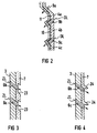
- the combustion chamber in FIG. 2 differs from the combustion chamber 1 in FIG. 1 only in that, in addition to the primary chamber 3, the secondary chamber 4 is also divided into partial combustion chambers 4a, 4b, 4c. Each partial combustion chamber 4a, 4b and 4c is assigned at least one inlet 9a, 9b and 9c. This results in a good mixing of the medium in the secondary chamber 4.
- the weak swirl already generated in the primary chamber 3 is also supported in the secondary chamber 4.
- the air supply and thus the combustion can be controlled well.
- the air inlets 6b, 6c in the primary chamber 3 can, for example, be designed such that the inner wall of the primary chamber 3, as shown in FIG. 3, has indentations 23, the Inlets 6b, 6c open into these indentations 23.
- the inlets 6b, 6c are in a protected position.
- Corresponding indentations for receiving the inlets 9b, 9c can also have the inner wall of the secondary chamber 4.
- a roof-shaped projection 24 can be arranged on the inner wall of the primary chamber 3 above an inlet 6b, 6c for the protection thereof.
- a corresponding roof-shaped projection can also be arranged above an inlet 9b, 9c on the inner wall of the secondary chamber 4.
- fuels in particular pyrolysis residues PR and smoldering gas SG, which originate from a smoldering drum, can be completely burned and converted into flue gas RG and liquid ash A or slag, without the need for complex and expensive coatings on the combustion chamber 1 and without frequent maintenance and repairs to the combustion chamber 1 are necessary.
Landscapes
- Engineering & Computer Science (AREA)
- Mechanical Engineering (AREA)
- General Engineering & Computer Science (AREA)
- Incineration Of Waste (AREA)
- Gasification And Melting Of Waste (AREA)
- Paper (AREA)
- Ceramic Products (AREA)
- Combustion Methods Of Internal-Combustion Engines (AREA)
- Chemical And Physical Treatments For Wood And The Like (AREA)
Abstract
Description
Die Erfindung betrifft eine Brennkammer, die mit einem Brenner ausgerüstet ist, und einen Einlaß für ein Gut aufweist, das Pyrolysereststoff und Schwelgas aus einem Pyrolysereaktor umfaßt, der Abfall in Schwelgas und im wesentlichen nichtflüchtigen Pyrolysereststoff umformt, wobei am Pyrolysereaktor insbesondere eine Austragsvorrichtung für den nichtflüchtigen Pyrolysereststoff angeschlossen ist, die einen Schwelgasabzugstutzen zum Abführen von Schwelgas aufweist, und wobei das Schwelgas und aufbereiteter Pyrolysereststoff der Brennkammer zugeleitet sind.The invention relates to a combustion chamber which is equipped with a burner and has an inlet for a product which comprises pyrolysis residue and carbonization gas from a pyrolysis reactor which converts waste into carbonization gas and essentially nonvolatile pyrolysis residue, the pyrolysis reactor in particular being a discharge device for the nonvolatile Pyrolysis residue is connected, which has a carbonization gas outlet for discharging carbonization gas, and wherein the carbonization gas and processed pyrolysis residue are fed to the combustion chamber.
Aus der EP 0 143 510 A1 ist ein Brenner für Biomasse bekannt, in den an vier verschiedenen Stellen Verbrennungsluft eingespeist wird. Die zugeleitete Biomasse ist feucht und wird im Brenner getrocknet und entgast. Der bekannte Brenner weist eine Brennkammer auf, deren gesamte Innenoberfläche mit einer feuerfesten Beschichtung versehen ist. Üblich ist bei derartigen Brennkammern eine Ausmauerung mit feuerfesten Schamottsteinen. Auch eine Beschichtung mit einer feuerfesten sogenannten Stampfmasse ist üblich.A burner for biomass is known from
In einer solchen Brennkammer wird bei Verbrennung von aschehaltigem Brennstoff während des Betriebes flüssige Asche gebildet, die die Oberflächen der Steine oder der Stampfmasse angreifen kann. Es ist daher nach einer bestimmten Betriebszeit eine Erneuerung oder Ausbesserung der Schamottsteine oder der Stampfmasse notwendig. Diese Betriebsintervalle zwischen zwei Instandsetzungen einer Brennkammer können durch die Verwendung besonders widerstandsfähiger Schamottsteine verlängert werden. Solche gegen flüsse Asche weitgehend resistenten Schamottsteine sind aber sehr teuer.In such a combustion chamber, when ash-containing fuel is burned, liquid ash is formed during operation, which can attack the surfaces of the stones or the ramming mass. It is therefore after a certain one Operating time, a renewal or repair of the firebricks or the ramming mass is necessary. These operating intervals between two repairs to a combustion chamber can be extended by using particularly resistant firebricks. Such firebricks, which are largely resistant to river ash, are very expensive.
Aus der EP 0 302 510 Al ist eine Anlage zur thermischen Abfallentsorgung bekannt. Mit dieser Anlage wird Abfall in einem Pyrolysereaktor in Schwelgas und im wesentlichen nichtflüchtigen Pyrolysereststoff umgeformt. Am Pyrolysereaktor ist eine Austragsvorrichtung für den nichtflüchtigen Pyrolysereststoff angeschlossen, die einen Schwelgasabzugstutzen zum Abführen von Schwelgas aufweist. Das Schwelgas und aufbereiteter, beispielsweise gemahlener Pyrolysereststoff gelangen in eine Brennkammer. Dort erfolgt eine Verbrennung, wobei schmelzflüssige Schlacke entsteht. Außerdem entsteht Rauchgas, das aus der Brennkammer über eine Rauchgasleitung abgeleitet wird. Auch die schmelzflüssige Schlacke wird aus der Brennkammer abgelassen. Nach Abkühlung liegt sie dann in verglaster Form vor.A system for thermal waste disposal is known from
Die Brennkammer dieser Anlage ist wie andere bekannte Brennkammern mit Schamottsteinen oder Stampfmasse ausgekleidet. Wie bei anderen Brennkammern ist eine teuere Auskleidung vorhanden, damit das Betriebsintervall zwischen zwei notwendigen Wartungen der Brennkammer möglichst groß ist.The combustion chamber of this system, like other known combustion chambers, is lined with firebricks or ramming paste. As with other combustion chambers, an expensive lining is provided so that the operating interval between two necessary maintenance of the combustion chamber is as large as possible.
Der Erfindung liegt die Aufgabe zugrunde, eine Brennkammer anzugeben, die kostengünstig zu erstellen ist und trotzdem nur selten gewartet werden muß. Insbesondere die innere Verkleidung der Brennkammer soll kostengünstig zu erstellen sein und eine lange, ungestörte Betriebszeit gewährleisten.The invention has for its object to provide a combustion chamber that is inexpensive to build and yet only rarely requires maintenance. In particular, the inner lining of the combustion chamber should be inexpensive to manufacture and ensure a long, undisturbed operating time.
Die Aufgabe wird gemäß der Erfindung dadurch gelöst, daß die Brennkammer zumindest dreiteilig ist, wobei eine Primärkammer, eine Sekundärkammer und ein Ascheaustragsraum hintereinander angeordnet sind, daß der Brenner der Primärkammer zugeordnet ist, wobei über den Brenner ein erster Luftstrom (Primärluft) in die Primärkammer gelangt, daß die Primärkammer einen Einlaß für einen zweiten Luftstrom (Sekundärluft) zur unterstöchiometrischen Verbrennung des Gutes bei einer Temperatur unterhalb des Ascheerweichungspunktes und ohne Schlackenfluß aufweist, wobei die Wände der Primärkammer nicht mit einem gegen flüssige Schlacke beständigen Material beschichtet sind, und daß die Sekundärkammer einen Einlaß für einen dritten Luftstrom (Tertiärluft) zur kurzfristigen, intensiven, vollständigen Verbrennung des Austrages aus der Primärkammer mit Schlackenfluß aufweist, wobei die Wände der Sekundärkammer mit einem gegen flüssige Schlacke beständigen Material beschichtet sind.The object is achieved according to the invention in that the combustion chamber is at least in three parts, a primary chamber, a secondary chamber and an ash discharge space being arranged one behind the other in that the burner is assigned to the primary chamber, a first air flow (primary air) into the primary chamber via the burner arrives that the primary chamber has an inlet for a second air stream (secondary air) for the substoichiometric combustion of the material at a temperature below the ash softening point and has no slag flow, the walls of the primary chamber not being coated with a material resistant to liquid slag, and the secondary chamber having an inlet for a third air stream (tertiary air) for short-term, intensive, complete combustion of the discharge from the primary chamber with slag flow, the walls of the secondary chamber being coated with a material resistant to liquid slag.
Der Ascheaustragsraum hat beispielsweise einen Boden, in dem sich ein Ascheauslaufloch befindet. Außerdem weist der Ascheaustragsraum beispielsweise eine Rauchgasabführöffnung auf.The ash discharge area has, for example, a floor in which there is an ash outlet hole. In addition, the ash discharge space has, for example, a flue gas discharge opening.
Die Primärkammer ist für eine unterstöchiometrische Verbrennung ausgelegt. Daß die Verbrennung stets unterstöchiometrisch bleibt, muß in der Primärkammer stets ein Luftunterschuß vorhanden sein. Durch Einlässe für zwei getrennte Luftströme, die Primärluft und die Sekundärluft, in der Primärkammer kann an jeder Stelle der Primärkammer stets der benötigte Luftstrom zur Verfügung stehen, ohne daß in einem Teil der Primärkammer, beispielsweise im oberen Bereich, zu viel Luft vorhanden wäre. Bedingt durch die unterstöchiometrische Verbrennung überschreitet die Temperatur in der Primärkammer den Ascheerweichungspunkt nicht. Der Ascheerweichungspunkt einer bestimmten Asche ist eine Temperatur, bei der sich definitionsgemäß eine bestimmte Verformung und Klebefähigkeit einstellt. Da der Ascheerweichungspunkt in der Primärkammer nicht überschritten wird, kann auch keine flüssige Asche oder Schlacke an die Innenauskleidung der Primärkammer gelangen. Dadurch ist eine Auskleidung der Primärkammer mit teueren flüssiger Asche oder Schlacke widerstehenden Schamottsteinen oder mit entsprechend geeigneter Stampfmasse nicht erforderlich.The primary chamber is designed for substoichiometric combustion. That the combustion always remains substoichiometric, there must always be an air deficit in the primary chamber. Inlets for two separate air flows, the primary air and the secondary air, in the primary chamber can always provide the required air flow at any point in the primary chamber without too much air being present in part of the primary chamber, for example in the upper region. Due to the substoichiometric combustion, the temperature in the primary chamber does not exceed the ash softening point. The ash softening point of a certain ash is a temperature at which, by definition, a certain deformation and adhesiveness occurs. Since the ash softening point in the primary chamber is not exceeded, no liquid ash or slag can get to the inner lining of the primary chamber. It is therefore not necessary to line the primary chamber with expensive refractory refractory bricks or with suitable ramming paste.
Die sich an die Primärkammer anschließende Sekundärkammer weist gemäß der Erfindung einen Einlaß für Tertiärluft auf. Durch diese Tertiärluft wird in der Sekundärkammer ein Luftüberschuß eingestellt, der eine kurzfristige, intensive und vollständige Verbrennung gewährleistet. Dabei überschreitet die Temperatur den Aschefließpunkt, und es kommt zu einem Schlakkenfluß auf der Innenoberfläche der Sekundärkammer. Der Aschefließpunkt einer bestimmten Asche ist eine Temperatur, bei der die Zähigkeit so niedrig ist, daß die Asche fließt. Die Sekundärkammer ist gemäß der Erfindung daher mit hitzebeständigem und gegen flüssige Schlacke beständigem Material beschichtet. Dieses Material ist teuerer als das für die Beschichtung der Primärkammer verwendete Material. Die Anlage nach der Erfindung benötigt das teuere Material aber nur zur Beschichtung eines Teiles der Brennkammer, nämlich der Sekundärkammer. Man kommt daher mit wenig teuerem Material aus.According to the invention, the secondary chamber adjoining the primary chamber has an inlet for tertiary air. This tertiary air creates an excess of air in the secondary chamber set, which ensures short-term, intensive and complete combustion. The temperature exceeds the ash flow point and a slag flow occurs on the inner surface of the secondary chamber. The ash flow point of a particular ash is a temperature at which the toughness is so low that the ash flows. The secondary chamber is therefore coated with heat-resistant and liquid slag-resistant material according to the invention. This material is more expensive than the material used to coat the primary chamber. The system according to the invention, however, only requires the expensive material to coat a part of the combustion chamber, namely the secondary chamber. You can get by with less expensive material.
An die Sekundärkammer schließt sich der Ascheaustragsraum an. In dessen Boden befindet sich ein Ascheauslaufloch. Nur der Boden des Ascheaustragsraumes, der mit flüssiger Asche oder Schlacke in Kontakt kommt, ist mit gegen flüssige Schlacke beständigem Material beschichtet. Der Ascheaustragsraum weist eine Rauchgasabführöffnung auf, an die ein Rauchgaskanal, der zu einem Kamin führt, angeschlossen sein kann.The ash discharge chamber is connected to the secondary chamber. There is an ash outlet hole in the bottom. Only the floor of the ash discharge area that comes into contact with liquid ash or slag is coated with material that is resistant to liquid slag. The ash discharge chamber has a flue gas discharge opening, to which a flue gas duct leading to a chimney can be connected.
Beim Einsatz der Brennkammer nach der Erfindung in einer Anlage zur thermischen Abfallentsorgung, einer sogenannten Schwel-Brenn-Anlage, wird in der Brennkammer aufbereiteter Pyrolysereststoff zusammen mit Schwelgas verbrannt. Es verbleiben Rauchgas und flüssige Asche oder Schlacke, die in einem Wasserbad zu Schmelzgranulat weiterverarbeitet werden kann.When the combustion chamber according to the invention is used in a plant for thermal waste disposal, a so-called smoldering plant, pyrolysis residue processed in the combustion chamber is burned together with smoldering gas. This leaves flue gas and liquid ash or slag, which can be further processed to melt granulate in a water bath.
Mit der Brennkammer nach der Erfindung wird der Vorteil erzielt, daß ein großer Teil der Brennkammer, die Primärkammer, ohne eine teuere Auskleidung auskommt. Nur ein kleiner Teil der Brennkammer, die Sekundärkammer benötigt eine gegen flüssige Schlacke beständige Auskleidung. Die Brennkammer nach der Erfindung ist kostengünstig auszuführen und gewährleistet eine lange, ungestörte Betriebszeit.With the combustion chamber according to the invention the advantage is achieved that a large part of the combustion chamber, the primary chamber, manages without an expensive lining. Only a small part of the combustion chamber, the secondary chamber requires a lining that is resistant to liquid slag. The combustion chamber according to the invention can be carried out inexpensively and ensures a long, undisturbed operating time.
Beispielsweise sind die Wände der Sekundärkammer gekühlt. Dadurch kann auch auf eine teuere Beschichtung des Inneren der Sekundärkammer zum Schutz gegen flüssige Asche und Schlacke verzichtet werden. Mit einer kostengünstigen Beschichtung ist eine lange, ungestörte Betriebszeit gewährleistet.For example, the walls of the secondary chamber are cooled. As a result, an expensive coating of the interior of the secondary chamber to protect against liquid ash and slag can also be dispensed with. With an inexpensive coating, a long, undisturbed operating time is guaranteed.
Es kann eine Beschichtung gewählt werden, die kostengünstiger ist als eine Beschichtung, die in einer ungekühlten Kammer notwendig wäre, in der flüssige Asche oder Schlacke fließt.A coating can be chosen which is less expensive than a coating which would be necessary in an uncooled chamber in which liquid ash or slag flows.
Der Einlaß für den zweiten Luftstrom (Sekundärluft) befindet sich beispielsweise im Brenner. Nach einem anderen Beispiel befindet sich der Einlaß für die Sekundärluft am oberen Abschnitt der Primärkammer seitlich neben dem Anschluß für den Brenner. Ein anderes Beispiel sieht vor, daß mehrere Einlässe für Sekundärluft an der Primärkammer über deren gesamte Länge verteilt angeordnet sind. Insbesondere damit wird der Vorteil erzielt, daß in der gesamten Primärkammer überall genau diejenige Luftkonzentration einzustellen ist, die eine unterstöchiometrische Verbrennung bei einer Temperatur unterhalb des Ascheerweichungspunktes sicherstellt. Die Luftzufuhr in die Primärkammer ist so zu wählen, daß einerseits die Temperatur des Ascheerweichungspunktes nicht überschritten wird und andererseits die unterstöchiometrische Verbrennung in der gesamten Primärkammer stets aufrechtzuerhalten ist. Das ist dadurch gewährleistet, daß neben der Primärluft Sekundärluft, insbesondere an den besonders ausgewählten Stellen, in die Primärkammer hineingelangen kann. Der Luftstrom ist so an jedem Punkt in der Primärkammer optimal einzustellen.The inlet for the second air stream (secondary air) is, for example, in the burner. According to another example, the inlet for the secondary air is located on the upper section of the primary chamber to the side next to the connection for the burner. Another example provides that several inlets for secondary air are arranged on the primary chamber distributed over its entire length. In particular, this has the advantage that the air concentration must be set everywhere in the entire primary chamber, which ensures substoichiometric combustion at a temperature below the ash softening point. The air supply to the primary chamber should be selected so that on the one hand the temperature of the ash softening point is not exceeded and on the other hand the substoichiometric combustion in the entire primary chamber must always be maintained. This is ensured by the fact that in addition to the primary air, secondary air, particularly at the specially selected points, can get into the primary chamber. The air flow can be optimally adjusted at every point in the primary chamber.
Beispielsweise sind ein Einlaß oder mehrere Einlässe für die Sekundärluft in der Primärkammer schräg, das heißt mit tangentialer Komponente, zur Wand der Primärkammer ausgerichtet. Damit wird im Medium, das sich in der Primärkammer befindet, ein Wirbel erzeugt, der sich von der Primärkammer aus in die Sekundärkammer hinein fortsetzt.For example, one or more inlets for the secondary air in the primary chamber are oriented obliquely, that is to say with a tangential component, to the wall of the primary chamber. This creates a vortex in the medium in the primary chamber, which continues from the primary chamber into the secondary chamber.
In der Primärkammer wird durch diese Zuführung von Sekundärluft das Medium vermischt. Der entstehende schwache Drall am Eingang der Sekundärkammer begünstigt die Bildung eines Dralls in der Sekundärkammer.This supply of secondary air mixes the medium in the primary chamber. The weak swirl that arises at the entrance of the secondary chamber favors the formation of a swirl in the secondary chamber.
Beispielsweise sind Einlässe für die Sekundärluft in der Primärkammer in parallelen Ebenen untereinander angeordnet. Entsprechend können auch zwei oder mehrere Einlässe für die Tertiärluft in der Sekundärkammer in parallelen Ebenen untereinander angeordnet sein. Durch diese Zuführung von Luft in mehreren Ebenen kann die Verbrennung in der Primärkammer aber auch in der Sekundärkammer gesteuert werden.For example, inlets for the secondary air in the primary chamber are arranged one below the other in parallel planes. Correspondingly, two or more inlets for the tertiary air can also be arranged in the secondary chamber in parallel planes. By supplying air at several levels, the combustion in the primary chamber can also be controlled in the secondary chamber.
Die Einlässe für Luft können in Einbuchtungen hinein münden, die in der Innenwand der Primärkammer und/oder der Sekundärkammer angeordnet sind. Dadurch sind die Einmündungen vor dem in der Brennkammer befindlichen Gut geschützt.The inlets for air can open into indentations which are arranged in the inner wall of the primary chamber and / or the secondary chamber. This protects the outlets from the material in the combustion chamber.
Dem Schutz einer Einmündung kann auch ein dachförmiger Vorsprung dienen, der beispielsweise oberhalb eines Einlasses an der Innenwand der Brennkammer angeordnet ist.A roof-shaped projection, which is arranged, for example, above an inlet on the inner wall of the combustion chamber, can also serve to protect an opening.
Beispielsweise ist die Primärkammer in hintereinander geschaltete Teilbrennkammern unterteilt. Einlässe für den zweiten Luftstrom befinden sich beispielsweise in jeder Teilbrennkammer, in deren oberem Abschnitt, also in Strömungsrichtung am Eingang der Teilbrennkammer. Mit der Unterteilung der Primärkammer in Teilbrennkammern und mit der Luftzuführung in jede dieser Teilbrennkammern wird eine optimale Luftzuführung in die Primärkammer und eine optimale Durchmischung des Mediums in der Primärkammer erzielt.For example, the primary chamber is divided into partial combustion chambers connected in series. Inlets for the second air flow are, for example, in each partial combustion chamber, in its upper section, that is, in the direction of flow at the entrance of the partial combustion chamber. With the subdivision of the primary chamber into partial combustion chambers and with the air supply in each of these partial combustion chambers, an optimal air supply into the primary chamber and an optimal mixing of the medium in the primary chamber is achieved.
Beispielsweise ist der Einlaß für Tertiärluft in die Sekundärkammer schräg, das heißt mit tangentialer Komponente zur Wand der Sekundärkammer ausgerichtet. Dadurch wird direkt in der Sekundärkammer ein Drall erzeugt, der die schweren Teile des Mediums in der Sekundärkammer zur Wand hin drückt. Dort wird flüssige Asche an der Wand abgeschieden und fließt entlang der Wand zur Austrittsöffnung der Sekundärkammer. Von dort gelangt die flüssige Asche in den Ascheaustragsraum. Die Wirkung des in der Sekundärkammer erzeugten Dralls ist deutlich verbessert, falls bereits in der Primärkammer ein Drall erzeugt worden ist. Durch die Erzeugung eines Dralls im Medium, das sich in der Brennkammer befindet, wird der Vorteil erzielt, daß flüssige Asche und Schlacke vom Rauchgas und auch von anderen Stoffen schnell und zuverlässig abzutrennen ist.For example, the inlet for tertiary air into the secondary chamber is inclined, that is, aligned with a tangential component to the wall of the secondary chamber. This will directly in the Secondary chamber creates a swirl that pushes the heavy parts of the medium in the secondary chamber towards the wall. There, liquid ash is deposited on the wall and flows along the wall to the outlet opening of the secondary chamber. From there, the liquid ash arrives in the ash discharge area. The effect of the swirl generated in the secondary chamber is significantly improved if a swirl has already been generated in the primary chamber. By generating a swirl in the medium, which is located in the combustion chamber, the advantage is achieved that liquid ash and slag can be separated from the flue gas and also from other substances quickly and reliably.
Wie die Primärkammer kann auch die Sekundärkammer in hintereinander geschaltete Teilbrennkammern unterteilt sein. Entsprechend befinden sich Einlässe für den dritten Luftstrom beispielsweise in jeder Teilbrennkammer der Sekundärkammer in deren oberen Abschnitt, also in Strömungsrichtung am Eingang der Teilbrennkammer. Mit der Unterteilung auch der Sekundärkammer in Teilbrennkammern und mit der Luftzuführung in jede dieser Teilbrennkammern ist eine genaue Steuerung der Verbrennung in der Sekundärkammer möglich. Es wird außerdem eine verbesserte Durchmischung des Mediums in der Sekundärkammer erzielt.Like the primary chamber, the secondary chamber can also be divided into partial combustion chambers connected in series. Correspondingly there are inlets for the third air flow, for example in each partial combustion chamber of the secondary chamber in its upper section, that is to say in the flow direction at the entrance of the partial combustion chamber. With the subdivision of the secondary chamber into partial combustion chambers and with the air supply to each of these partial combustion chambers, precise control of the combustion in the secondary chamber is possible. Improved mixing of the medium in the secondary chamber is also achieved.
Die Wände der Sekundärkammer sind von innen beispielsweise mit Steinen abgedeckt. Diese Steine bestehen aus einem Material, das widerstandsfähig ist und durch Schlacke und Asche nicht angegriffen wird. Nach einem weiteren Beispiel sind die Wände der Sekundärkammer von innen mit einer Stampfmasse beschichtet, die entsprechende Eigenschaften hat. Da nur die Sekundärkammer mit hochwertigen Steinen oder Stampfmassen auszustatten ist, ergibt das einen Kostenvorteil gegenüber einer Brennkammer, die ganz mit hochwertigen Steinen oder Stampfmassen ausgekleidet werden muß.The walls of the secondary chamber are covered with stones, for example, from the inside. These stones are made of a material that is resistant and is not attacked by slag and ash. According to a further example, the walls of the secondary chamber are coated from the inside with a ramming compound that has the appropriate properties. Since only the secondary chamber is to be equipped with high-quality stones or ramming compounds, this results in a cost advantage compared to a combustion chamber, which must be lined entirely with high-quality stones or ramming compounds.
Um die Wände der Sekundärkammer noch preisgünstiger zu machen, sind diese Wände gekühlt. Dazu enthalten die Wände der Sekundär kammer beispielsweise Kühlkanäle, die ein Kühlmittel, insbesondere Wasser oder Luft, aufnehmen. Durch diese ständige Kühlung der Sekundärkammerwände von außen her wird eine starke Überhitzung der mit der flüssigen Asche oder Schlacke benetzten Innenoberflächen der Wände verhindert. Folglich können selbst in der Sekundärkammer, wie schon in der Primärkammer, preisgünstige Auskleidungen verwendet werden. Durch die Kühlung bildet sich auf der Oberfläche der Auskleidung eine dünne, feste Schlackenschicht, auf der sich nach innen ein flüssiger Schlackefilm bildet. Die feste Schlackenschicht schützt das darunterliegende Material der Auskleidung vor einem Angriff durch die flüssige Schlacke. Man benötigt also für die Auskleidung der Sekundärkammer kein teueres gegen Schlackenfluß resistentes Material.In order to make the walls of the secondary chamber even cheaper, these walls are cooled. To do this, the walls contain the secondary Chamber, for example, cooling channels that hold a coolant, especially water or air. This constant cooling of the secondary chamber walls from the outside prevents excessive overheating of the inner surfaces of the walls wetted with the liquid ash or slag. As a result, inexpensive liners can be used even in the secondary chamber, as in the primary chamber. As a result of the cooling, a thin, firm layer of slag forms on the surface of the lining, on which a liquid slag film forms on the inside. The solid slag layer protects the lining material underneath from being attacked by the liquid slag. So you do not need an expensive material resistant to slag flow for the lining of the secondary chamber.
Der Primärkammer oder der Sekundärkammer oder dem Ascheaustragsraum ist beispielsweise Flugstaub zuführbar. Die Zufuhr kann über besonderer Zuführöffnungen, aber auch durch den Brenner oder zusammen mit Sekundärluft oder Tertiärluft erfolgen. Läßt sich der Flugstaub aufgrund seiner Eigenschaften leicht in ein Schlackebad einbinden, dann ist es besonders vorteilhaft, den Flugstaub direkt dem Ascheaustragsraum zuzuführen. Der Flugstaub wird auf diese Weise in die Schlacke eingebunden.Airborne dust, for example, can be fed to the primary chamber or the secondary chamber or the ash discharge chamber. The supply can take place via special supply openings, but also through the burner or together with secondary air or tertiary air. If the dust can be easily incorporated into a slag bath due to its properties, then it is particularly advantageous to feed the dust directly to the ash discharge area. In this way, the flying dust is incorporated into the slag.
Der Ascheaustragsraum ist beispielsweise breiter als der Ausgang der Sekundärkammer. Dadurch gelangt die aus der Sekundärkammer aus getragene Schlacke oder flüssige Asche nicht an die Seitenwände des Ascheaustragsraumes. Deshalb muß nur der Boden des Ascheaustragsraumes mit gegen flüssige Schlacke resistentem Material belegt sein. Das können teuere Steine oder Stampfmassen sein, oder auch kostengünstige Steine oder Stampfmassen, falls eine Kühlvorrichtung im Boden des Ascheaustragsraumes vorhanden ist. Die Kühlvorrichtung kann derart aufgebaut sein, daß der Boden des Ascheaustragsraumes Kühlkanäle enthält, zur Aufnahme eines Kühlmittels, insbesondere von Wasser oder Luft.The ash discharge space is, for example, wider than the exit of the secondary chamber. As a result, the slag or liquid ash carried out of the secondary chamber does not reach the side walls of the ash discharge space. Therefore, only the floor of the ash discharge area must be covered with material that is resistant to liquid slag. This can be expensive stones or ramming masses, or also inexpensive stones or ramming masses, if a cooling device is available in the floor of the ash discharge chamber. The cooling device can be constructed such that the bottom of the ash discharge space cooling channels contains, for receiving a coolant, especially water or air.
Der Boden des Ascheaustragsraumes verläuft z.B. waagerecht, wodurch sich bei Kühlung um das Ascheauslaufloch herum eine Schlackenschicht ausbilden kann, die den Boden vor Errosion schützt.The floor of the ash discharge area runs e.g. horizontal, which, when cooled, can form a layer of slag around the ash outlet hole that protects the floor from erosion.
Der Ausgang der Sekundärkammer ist in der Sekundärkammer beispielsweise von einem Ring umgeben, der eine Ablaufstelle an einer von der Rauchgasabführöffnung abgewandten Seite aufweist. Dazu ist, von einer fiktiven horizontalen Ebene aus gemessen, die Höhe dieses Ringes an einer vom Rauchgasabführstutzen des Ascheaustragsraumes abgewandten Stelle kleiner als sonst. Dadurch ergibt sich eine Rinne, die um den Ausgang der Sekundärkammer herum verläuft. Beim Betrieb der Brennkammer füllt sich diese Rinne mit flüssiger Asche oder Schlacke an. Dort wo der Ring gegenüber einer horizontalen Ebene am niedrigsten ist, fließt die Schlacke sowie die Rinne gefüllt ist, in einem Strahl aus der Sekundärkammer in den Ascheaustragsraum. Da die niedrigste Stelle des Ringes sich an einer vom Rauchgasabführstutzen des Ascheaustragsraumes abgewandten Stelle befindet, fließt dort die gesamte flüssige Schlacke mit nur einem Strahl in den Ascheaustragsraum hinein. Mit dem Ring wird folglich der Vorteil erzielt, daß sich nur ein Aschestrahl von der Sekundärkammer in den Ascheaustragsraum ergibt, der durch ausströmendes Rauchgas nicht gekreuzt wird. Somit wird der Ascheausfluß nicht durch die Rauchgasströmung gestört. Falls flüssige Asche und Rauchgas beide unkontrolliert aus dem breiten Ausgang der Sekundärkammer herausfließen würden, würde eine Vermischung von Rauchgas und Schlacke im Ascheaustragsraum erfolgen können. Statt zum Ascheauslaufloch zu gelangen, würden kleine Schlackenteile mit dem Rauchgas weggetragen werden. Das wird durch den Ring in der Sekundärkammer verhindert.The exit of the secondary chamber is surrounded, for example, in the secondary chamber by a ring which has a drainage point on a side facing away from the flue gas discharge opening. For this purpose, measured from a fictitious horizontal plane, the height of this ring at a point facing away from the flue gas discharge nozzle of the ash discharge space is smaller than usual. This results in a channel that runs around the exit of the secondary chamber. When the combustion chamber is operating, this channel fills with liquid ash or slag. Where the ring is the lowest in relation to a horizontal plane, the slag and the channel are filled in a jet from the secondary chamber into the ash discharge area. Since the lowest point of the ring is located at a point facing away from the flue gas discharge nozzle of the ash discharge area, the entire liquid slag flows into the ash discharge area with only one jet. The ring therefore has the advantage that there is only one ash jet from the secondary chamber into the ash discharge space, which is not crossed by the flue gas flowing out. The ash flow is therefore not disturbed by the flue gas flow. If both liquid ash and flue gas flow out of the wide exit of the secondary chamber in an uncontrolled manner, flue gas and slag could be mixed in the ash discharge chamber. Instead of getting to the ash outlet hole, small pieces of slag would be carried away with the flue gas. This is prevented by the ring in the secondary chamber.
Im Rauchgasabführstutzen des Ascheaustragsraumes ist beispielsweise ein Aschefangrost angeordnet. Damit wird der Vorteil erzielt, daß weniger Ascheteilchen in den Rauchgaskanal gelangen. Solche Teilchen würden in der Rauchgasleitung vorhandene Wärmetauscherheizflächen verschmutzen.An ash trap, for example, is arranged in the flue gas discharge nozzle of the ash discharge space. This has the advantage that fewer ash particles get into the flue gas duct. Such particles would contaminate existing heat exchanger heating surfaces in the flue gas line.
Beispielsweise ist im Ascheaustragsraum ein Aufheizbrenner angeordnet. Er wird eingesetzt, falls die aus der Sekundärkammer kommende flüssige Schlacke oder Asche schlechte Fließeigenschaften haben sollte. Dann wird die Schlacke im Ascheaustragsraum nochmals erwärmt, so daß sie zum Ascheauslaufloch gelangt und dort austritt. Bei ausreichender Fließfähigkeit der Schlacke oder Asche bleibt der Aufheizbrenner ausgeschaltet. Der Aufheizbrenner wird mit einem externen Brennmaterial gespeist. Er kann aber auch mit Schwelgas gespeist sein, das einem Pyrolysereaktor entstammt. Dadurch wird externes Brennmaterial eingespart.For example, a heating burner is arranged in the ash discharge area. It is used if the liquid slag or ash coming from the secondary chamber should have poor flow properties. Then the slag in the ash discharge space is heated again so that it reaches the ash outlet hole and exits there. If the slag or ash flows sufficiently, the heating burner remains switched off. The heating burner is fed with an external fuel. However, it can also be fed with carbonization gas that originates from a pyrolysis reactor. This saves external fuel.
Mit der Brennkammer nach der Erfindung wird insbesondere der Vorteil erzielt, daß bei kostengünstiger Ausführung der Brennkammer lange Betriebsintervalle ohne Wartungsarbeiten oder Reparaturarbeiten an der Brennkammer durchführbar sind.The combustion chamber according to the invention has the particular advantage that long operating intervals can be carried out without maintenance or repair work on the combustion chamber if the combustion chamber is inexpensive.
In dem zu behandelnden Gut, besonders aber im Rückstand der unterstöchiometrischen Verbrennung wird beispielsweise ein Drall erzeugt, wodurch die sich bildende flüssige Asche nach außen getragen wird und an einer Behälterwand, z.B. der Brennkammerwand, herunter fließen kann. Die Trennung von Rauchgas und flüssiger Asche wird dadurch verbessert.For example, a swirl is generated in the material to be treated, but especially in the residue of the substoichiometric combustion, as a result of which the liquid ash which is formed is carried outside and against a container wall, e.g. the combustion chamber wall. This improves the separation of flue gas and liquid ash.
Dem zu behandelnden Gut oder dem Rückstand der unterstöchiometrischen Verbrennung wird beispielsweise Flugstaub beigemischt, der der Einrichtung der Erfindung entstammen kann und der somit zurückgeführt wird. Flugstaub kann auch der noch fließenden Asche oder Schlacke beigemischt werden. Damit wird der Flugstaub vorteilhaft ganz oder teilweise in später festes Schlackengranulat eingebunden.The material to be treated or the residue of the substoichiometric combustion is admixed, for example, with airborne dust which can originate from the device of the invention and which is thus returned. Dust can also fly be mixed with the still flowing ash or slag. The flight dust is thus advantageously wholly or partly incorporated into later solid slag granules.
Beispielsweise wird die flüssige Asche, nachdem sie gebildet worden ist, nochmals aufgeheizt, damit ein frühzeitiges Erstarren verhindert wird. Die Schlacke fließt dann besser aus dem Ascheaustragsraum der Brennkammer heraus.For example, the liquid ash, after it has been formed, is heated again to prevent premature solidification. The slag then flows better out of the ash discharge chamber of the combustion chamber.
Schließlich kann das entstandene Rauchgas nach Abkühlung in einem Wärmetauscher im Brenner oder in separaten Zuführstellen z.B. zusammen mit der Verbrennungsluft in die Brennkammer eingespeist werden. Dadurch ist die notwendige Temperatur an jeder Stelle der Brennkammer einzustellen.Finally, the resulting flue gas can be cooled in a heat exchanger in the burner or in separate feed points e.g. are fed into the combustion chamber together with the combustion air. This means that the required temperature can be set at every point in the combustion chamber.
Mit der Anlage nach der Erfindung wird der Vorteil erzielt, daß zu behandelnde Gut, das insbesondere Pyrolysereststoff und Schwelgas aus einem Schwel-Brenn-Verfahren ist, in einer kostengünstig zu erstellenden Brennkammer, die wenig Wartungs- und Reparaturaufwand benötigt, zuverlässig in flüssige Asche und Rauchgas zu zerlegen ist.With the plant according to the invention, the advantage is achieved that the material to be treated, which is in particular pyrolysis residue and carbonization gas from a carbonization process, in a cost-effective combustion chamber that requires little maintenance and repair, reliably in liquid ash and Flue gas is to be dismantled.
Ein Ausführungsbeispiel der Anlage nach der Erfindung wird anhand der Zeichnung näher erläutert.
- FIG 1
- zeigt eine Brennkammer mit in Teilbrennkammern unterteilter Primärkammer.
- FIG 2
- zeigt schematisch eine Wand einer Sekundärkammer, die in Teilbrennkammern unterteilt ist.
- FIG 3
- zeigt schematisch eine Wand einer Brennkammer mit Einbuchtungen zur Aufnahme von Luftzuführungen.
- FIG 4
- zeigt schematisch eine Wand einer Brennkammer mit Luftzuführungen und darüber angeordneten dachförmigen Vorsprüngen.
- FIG. 1
- shows a combustion chamber with the primary chamber divided into partial combustion chambers.
- FIG 2
- shows schematically a wall of a secondary chamber, which is divided into partial combustion chambers.
- FIG 3
- shows schematically a wall of a combustion chamber with indentations for receiving air supplies.
- FIG 4
- schematically shows a wall of a combustion chamber with air inlets and roof-shaped projections arranged above it.
Eine Brennkammer 1 nach Figur 1, die mit einem Brenner 2 ausgerüstet ist, ist dreiteilig aufgebaut. Dabei sind eine Primärkammer 3, eine Sekundärkammer 4 und ein Ascheaustragsraum 5 hintereinander angeordnet. Der Brenner 2 ist der Primärkammer 3 zugeordnet. Die Primärkammer 3 besteht aus drei hintereinander angeordneten Teilbrennkammern 3a, 3b und 3c. Die Primärkammer 3 kann aber auch einteilig sein. Über den Brenner 2 gelangt ein zumindest teilweise brennbares Gut, das Pyrolysereststoff PR und Schwelgas SG aus einer Schwel-Brenn-Anlage sein kann, in die Primärkammer 3. Auch ein Primärluft genannter erster Luftstrom EL gelangt über den Brenner 2 in die Primärkammer 3. Die Primärkammer 3 weist über ihre Länge verteilt Einlässe 6a, 6b, 6c und 6d für einen Sekundärluft genannten zweiten Luftstrom ZL auf. Dabei ist jeder Teilbrennkammer 3a, 3b und 3c mindestens ein Einlaß 6a, 6b und 6c zugeordnet. Mindestens ein weiterer Einlaß 6d kann sich im Brenner 2 befinden. Durch eine tangentiale Anordnung zumindest einiger der Einlässe 6a bis d werden in dem in der Primärkammer 3 strömenden Medium Wirbel erzeugt, die eine gute Durchmischung des Mediums zur Folge haben. Es wird auch in der Primärkammer 3 ein schwacher Drall erzeugt, der sich in die Sekundärkammer 4 hinein fortpflanzt. Die Luftzufuhr in die Primärkammer 3 ist so bemessen, daß dort nur eine unterstöchiometrische Verbrennung erfolgt. Die Temperatur bleibt unterhalb des Ascheerweichungspunktes, so daß flüssige Asche A oder Schlacke nicht entsteht. Daher reicht eine einfache Auskleidung 7 der Primärkammer 3 beispielsweise mit kostengünstigen Steinen aus. Über einen Ausgang 8, der ohne oder mit Einziehung ausgebildet sein kann, steht die Primärkammer 3 unmittelbar mit der Sekundärkammer 4 in Verbindung. In dem der Primärkammer 3 zugewandten Bereich der Sekundärkammer 4 ist zumindest ein Einlaß 9 für einen Tertiärluft genannten dritten Luftstrom DL angeordnet. Dieser Luftstrom DL ist so bemessen, daß in der Sekundärkammer 4 eine vollständige Verbrennung des aus der Primärkammer 3 zugespeisten Rückstandes R erfolgt. Diese Verbrennung geschieht bei einer Temperatur oberhalb des Ascheerweichungspunktes, so daß flüssige Asche A oder Schlacke entsteht. Auch die Einlässe 9 für den dritten Luftstrom DL sind, wie schon die Einlässe 6a bis d, für den zweite Luftstrom ZL schräg, das heißt mit tangentialer Komponente, zur Wand der Brennkammer 1 ausgerichtet. Dadurch entsteht im Rückstand R, der sich in der Sekundärkammer 4 befindet, ein Drall, durch den flüssige Asche A oder Schlacke auf der Innenoberfläche der Sekundärkammer 4 abgeschieden wird. Dort fließt die flüssige Asche A nach unten. Um Beschädigungen vorzubeugen, sind die Innenwände der Sekundärkammer 4 mit einer Schicht 10 aus Steinen oder aus Stampfmasse versehen. Damit auch weniger teueres Material für die Schicht 10 der Sekundärkammer 4 ausreicht, befinden sich in den Wänden der Sekundärkammer 4 Kühlkanäle 11, durch die ein Kühlmittel, insbesondere Wasser oder Luft, strömt. Durch die ständige Kühlung werden die Wände der Sekundärkammer 4 durch die flüssige Asche A gar nicht oder nur wenig angegriffen, da sich zwischen der flüssigen Aschenschicht und der gekühlten Wand eine feste Schlackenschicht aufgrund der Kühlung ausbildet. An die Sekundärkammer 4 schließt sich über einen engen Ausgang 12 der Ascheaustragsraum 5 an. In diesen Ascheaustragsraum 5 hinein gelangt die flüssige Asche A oder Schlacke über eine ringförmige Rinne 13, die den Ausgang 12 umschließt und von diesem durch einen ringförmigen Wulst 14 getrennt ist. Der Wulst 14 hat gegenüber einer fiktiven horizontalen Ebene an einem bestimmten Punkt eine minimale Höhe. Dadurch ist eine Ablaufstelle 14a gebildet. Flüssige Asche A, die an den Wänden der Sekundärkammer 4 herunterfließt, sammelt sich zunächst in der Rinne 13 und überschreitet dann den Wulst 14 an dessen niedrigsten Punkt, nämlich an der Ablaufstelle 14a. Durch das Ansammeln der flüssigen Asche A vor der Abgabe in den Ascheaustragsraum 5 ist ein gleichmäßiger, kontinuierlicher Aschestrahl gegeben. Dadurch, daß der Ausgang 12 eng ist, gelangt dort Rauchgas RG mit hoher Geschwindigkeit in den Ascheaustragsraum 5. Der zunächst nach unten gerichtete Rauchgasstrom wird auf einem Boden 15 des Ascheaustragsraumes 5 umgelenkt. Der Boden 15 wirkt dabei wie eine Prallplatte. Dabei werden Ascheteilchen aus dem Rauchgas RG abgeschieden.A
Der Ascheaustragsraum 5 weist eine Rauchgasabführöffnung 16 auf, durch die das Rauchgas RG abgeleitet wird. Vor der Rauchgasabführöffnung 16 befindet sich bei Bedarf ein Aschefangrost 17, der weitere Ascheteilchen zurückhält. Zur Abfuhr der flüssigen Asche A oder Schlacke befindet sich im Ascheaustragsraum 5 ein Ascheauslaufloch 18. Dieses Ascheauslaufloch 18 wird von heißem Rauchgas RG überstrichen und wird damit erhitzt, so daß Asche A oder Schlacke im Ascheauslaufloch 18 nicht erstarren kann. Das Ascheauslaufloch 18 kann daher nicht verstopfen.The
Der Ascheaustragsraum 5 ist breiter als der Ausgang 12 der Sekundärkammer 4. Daher kann flüssige Asche A oder Schlacke nicht an die Seitenwände des Ascheaustragsraumes 5 gelangen, die daher nicht aus hochgradig widerstandsfähigem Material zu bestehen brauchen. Der Boden 15 des Ascheaustragsraumes 5 ist ähnlich wie die Wände der Sekundärkammer 4 mit einer Schicht 19 aus Stampfmasse oder Steinen versehen und enthält häufig Kühlkanäle 20.The
Auch in den Seitenwänden können Kühlkanäle vorhanden sein. Bedingt durch die Kühlung bildet sich im Laufe des Betriebes der Brennkammer 1 auf dem Boden 15 des Ascheaustragsraumes 5 eine feste Schlackenschicht aus, die den Boden 15 vor Erosion schützt. Auf dieser festen Schlackenschicht, die als Wärmedämmschicht dient, fließt die flüssige Asche A zum Ascheauslaufloch 18 und gelangt von dort in einen Wasserbehälter 21, wo sie granuliert. Die niedrigste Stelle des ringförmigen Wulstes 14 um den Ausgang 12, die Ablaufstelle 14a der Sekundärkammer 4 befindet sich an einer Position, die den größten Abstand zur Rauchgasabführöffnung 16 hat. Dadurch ist gewährleistet, daß sich im Ascheaustragsraum 5 flüssige Asche A und Rauchgas RG nicht kreuzen, was zu einer Verwirbelung des Rauchgases RG und zum Mitreißen von flüssiger Asche in den Rauchgasen führen würde. Um gegebenenfalls die flüssige Asche A im Ascheaustragsraum 5 flüssig zu halten, befindet sich im Ascheaustragsraum 5 ein Aufheizbrenner 22, der mit einem externen Brennstoff B oder auch mit Schwelgas SG einer Schwelbrennanlage gespeist sein kann. Flugstaub FS, der zuvor aus dem Rauchgas RG herausgefiltert wurde, und auch Rauchgas RG können in die Brennkammer 1 zurückgespeist werden.Cooling ducts can also be present in the side walls. Due to the cooling, a solid slag layer is formed on the
Die Brennkammer der Figur 2 unterscheidet sich von der Brennkammer 1 nach Figur 1 nur dadurch, daß neben der Primärkammer 3 auch die Sekundärkammer 4 in Teilbrennkammern 4a, 4b, 4c unterteilt ist. Dabei ist jeder Teilbrennkammer 4a, 4b und 4c mindestens ein Einlaß 9a, 9b und 9c zugeordnet. Dadurch wird eine gute Durchmischung des Mediums in der Sekundärkammer 4 bewirkt. Der bereits in der Primärkammer 3 erzeugte schwache Drall wird auch in der Sekundärkammer 4 unterstützt. Außerdem läßt sich die Luftzufuhr und damit die Verbrennung gut steuern.The combustion chamber in FIG. 2 differs from the
Die Lufteinlässe 6b, 6c in der Primärkammer 3 können beispielsweise so gestaltet sein, daß die Innenwand der Primärkammer 3, wie in Figur 3 gezeigt, Einbuchtungen 23 aufweist, wobei die Einlässe 6b, 6c in diese Einbuchtungen 23 hinein münden. Die Einlässe 6b, 6c befinden sich dabei in einer geschützten Position. Entsprechende Einbuchtungen zur Aufnahme der Einlässe 9b, 9c kann auch die Innenwand der Sekundärkammer 4 aufweisen.The
Nach Figur 4 kann oberhalb eines Einlasses 6b, 6c zu dessen Schutz ein dachförmiger Vorsprung 24 an der Innenwand der Primärkammer 3 angeordnet sein. Ein entsprechender dachförmiger Vorsprung kann auch oberhalb eines Einlasses 9b, 9c an der Innenwand der Sekundärkammer 4 angeordnet sein.According to FIG. 4, a roof-shaped
In der Brennkammer 1 können Brennstoffe, insbesondere Pyrolysereststoff PR und Schwelgas SG, die einer Schweltrommel entstammen, vollständig verbrannt und in Rauchgas RG und flüssige Asche A oder Schlacke umgewandelt werden, ohne daß aufwendige und teuere Beschichtungen der Brennkammer 1 notwendig wären und ohne daß häufige Wartungen und Reparaturen der Brennkammer 1 notwendig sind.In the
Claims (28)
- Combustion chamber (1):a) which is equipped with a burner (2);b) which comprises an inlet for a substance which contains pyrolysis residue (PR) and incompletely burned gas (SG) from a pyrolysis reactor which converts waste into incompletely burned gas (SG) and into substantially non-volatile pyrolysis residue (PR), there being connected to the pyrolysis reactor in particular a discharge apparatus for the non-volatile pyrolysis residue (PR), which apparatus comprises an incompletely burned gas vent connection for discharging incompletely burned gas (SG), and the incompletely burned gas (SG) and prepared pyrolysis residue (PR) being delivered to the inlet for the substance;c) which is in at least three parts, a primary chamber (3), a secondary chamber (4) and an ash discharge chamber (5) being disposed in series; andd) of which the burner (2) is associated with the primary chamber (3), a first air flow (primary air) (EL) passing into the primary chamber (3) via the burner (2);e) of which the primary chamber (3) comprises an inlet (6a, 6b, 6c, 6d) for a second air flow (secondary air) (ZL) for the substoichiometric combustion of the substance at a temperature below the ash softening point and without clinker flux, the walls of the primary chamber (3) not being coated with a material which is resistant to fluid clinker; andf) of which the secondary chamber (4) comprises an inlet (9) for a third air flow (tertiary air) (DL) for the brief, intensive and complete combustion of the discharge from the primary chamber (3) with clinker flux, the walls of the secondary chamber (4) being coated with a material which is resistant to fluid clinker.
- Combustion chamber according to Claim 1, characterized in that the ash discharge chamber (5) has a base (15) in which there is an ash outlet hole (18).
- Combustion chamber according to either of Claims 1 and 2, characterized in that the ash discharge chamber (5) comprises a flue gas vent opening (16).
- Combustion chamber according to any one of Claims 1 to 3, characterized in that the walls of the secondary chamber (4) are cooled.
- Combustion chamber (1) according to any one of Claims 1 to 4, characterized in that the inlet (6d) for the second air flow (secondary air) (ZL) is in the burner (2).
- Combustion chamber (1) according to any one of Claims 1 to 5, characterized in that the inlet (6a) for the second air flow (secondary air) (ZL) is located in the upper portion of the primary chamber (3) laterally of the burner (2).
- Combustion chamber (1) according to any one of Claims 1 to 6, characterized in that a plurality of inlets (6a - 6d) for the second air flow (secondary air) (ZL) is disposed in the primary chamber (3) distributed over the height thereof.
- Combustion chamber (1) according to any one of Claims 1 to 7, characterized in that an inlet (6a) or a plurality of inlets (6a - 6d) for the second air flow (ZL) is disposed in the primary chamber (3) aligned obliquely relative to the wall of the primary chamber (3).
- Combustion chamber (1) according to any one of Claims 1 to 8, characterized in that a plurality of inlets (6a - 6d) for the second air flow (ZL) in the primary chamber (3) and/or a plurality of inlets (9, 9a - 9c) for the third air flow (DL) in the secondary chamber (4) are disposed below one another in parallel planes.
- Combustion chamber (1) according to any one of Claims 1 to 9, characterized in that an inlet (6b, 6c, 6, 9) opens into an indentation (23) disposed in the wall of the primary chamber (3) and/or of the secondary chamber (4).
- Combustion chamber (1) according to any one of Claims 1 to 10, characterized in that a roof-like projection (24) is disposed above the inlet (6b, 6c, 6, 9) inside the chamber (3, 4).
- Combustion chamber (1) according to any one of Claims 1 to 11, characterized in that the primary chamber (3) is divided into partial combustion chambers (3a, 3b, 3c) connected in series.
- Combustion chamber (1) according to Claim 12, characterized in that the inlets (6a - 6c) for the second air flow (secondary air) (ZL) are located in the upper portion of each partial combustion chamber (3a, 3b, 3c).
- Combustion chamber (1) according to any one of Claims 1 to 13, characterized in that an inlet (9) or a plurality of inlets (9a - 9c) for the third air flow (DL) (tertiary air) is disposed in the secondary chamber (4) aligned obliquely relative to the wall of the secondary chamber (4).
- Combustion chamber (1) according to any one of Claims 1 to 14, characterized in that the secondary chamber (4) is divided into partial combustion chambers (4a, 4b, 4c) connected in series.
- Combustion chamber (1) according to Claim 15, characterized in that the inlets (9a - 9c) for the third air flow (tertiary air) (DL) are located in the upper portion of each partial combustion chamber (4a, 4b, 4c).
- Combustion chamber (1) according to any one of Claims 1 to 16, characterized in that the inner walls of the secondary chamber (4) are covered with bricks.
- Combustion chamber (1) according to any one of Claims 1 to 17, characterized in that the walls of the secondary chamber (4) are provided internally with a layer (10) of tamping clay.
- Combustion chamber (1) according to any one of Claims 1 to 18, characterized in that the walls of the secondary chamber (4) contain cooling ducts (11) for receiving a coolant, in particular water or air.
- Combustion chamber (1) according to any one of Claims 1 to 19, characterized in that fly ash (FS) can be delivered to the primary chamber (3) or the secondary chamber (4) or the ash discharge chamber (5).
- Combustion chamber (1) according to any one of Claims 1 to 20, characterized in that the ash discharge chamber (5) is wider than the outlet (12) of the secondary chamber (4); and in that only the base (15) and not the side walls of the ash discharge chamber (5) is coated and/or cooled.
- Combustion chamber (1) according to any one of Claims 1 to 21, characterized in that the base (15) of the ash discharge chamber (5) is provided with a layer (19) of bricks or tamping clay.
- Combustion chamber (1) according to any one of Claims 1 to 22, characterized in that the base (15) of the ash discharge chamber (5) contains cooling ducts (20) for receiving a coolant, in particular water or air.
- Combustion chamber (1) according to any one of Claims 1 to 23, characterized in that the ash discharge chamber (5) has a horizontal base (15).
- Combustion chamber (1) according to any one of Claims 2 to 24, characterized in that the outlet (12) of the secondary chamber (4) in the secondary chamber (4) is surrounded by an annular bead (14) which comprises a drain point (14a) on a side remote from the flue gas vent opening (16).
- Combustion chamber (1) according to any one of Claims 2 to 25, characterized in that an ash catcher grate (17) is disposed in the flue gas vent connection (16) of the ash discharge chamber (5).
- Combustion chamber (1) according to any one of Claims 1 to 26, characterized in that a reheater burner (22) is disposed in the ash discharge chamber (5).
- Combustion chamber (1) according to Claim 27, characterized in that the reheater burner (22) is fed with incompletely burned gas (SG).
Applications Claiming Priority (2)
| Application Number | Priority Date | Filing Date | Title |
|---|---|---|---|
| EP89113285 | 1989-07-19 | ||
| EP89113285 | 1989-07-19 |
Publications (2)
| Publication Number | Publication Date |
|---|---|
| EP0409037A1 EP0409037A1 (en) | 1991-01-23 |
| EP0409037B1 true EP0409037B1 (en) | 1994-09-21 |
Family
ID=8201644
Family Applications (1)
| Application Number | Title | Priority Date | Filing Date |
|---|---|---|---|
| EP90113091A Expired - Lifetime EP0409037B1 (en) | 1989-07-19 | 1990-07-09 | Combustion chamber for the combustion of at least partially combustible materials |
Country Status (11)
| Country | Link |
|---|---|
| US (1) | US5050512A (en) |
| EP (1) | EP0409037B1 (en) |
| JP (1) | JPH0814363B2 (en) |
| AT (1) | ATE112032T1 (en) |
| CA (1) | CA2021344A1 (en) |
| DD (1) | DD296744A5 (en) |
| DE (1) | DE59007204D1 (en) |
| DK (1) | DK0409037T3 (en) |
| ES (1) | ES2059906T3 (en) |
| NO (1) | NO172007C (en) |
| PT (1) | PT94746A (en) |
Families Citing this family (22)
| Publication number | Priority date | Publication date | Assignee | Title |
|---|---|---|---|---|
| DE3724024A1 (en) * | 1987-07-21 | 1989-02-02 | Abus Kg | Rope guidance for barrels |
| FR2671606B1 (en) * | 1991-01-14 | 1993-04-16 | Trepaud | PROCESS AND PLANT FOR THE INCINERATION OF WASTE. |
| JPH0772608B2 (en) * | 1991-06-24 | 1995-08-02 | 株式会社神戸製鋼所 | Waste combustion and melting equipment |
| JP2977368B2 (en) * | 1992-05-01 | 1999-11-15 | 三菱重工業株式会社 | Coal combustor and its slag discharger |
| FR2698156B1 (en) * | 1992-11-16 | 1995-01-27 | Rhone Poulenc Chimie | Process for the thermal treatment of an effluent comprising polluting organic materials or an inorganic compound. |
| DE4409951A1 (en) | 1994-03-23 | 1995-09-28 | Abfallwirtschaftsges | Device for burning dusty materials |
| DE69718020T2 (en) * | 1996-09-04 | 2003-11-06 | Ebara Corp., Tokio/Tokyo | MELTING TUBES AND METHOD FOR GASIFYING WASTE IN THE SAME |
| JP4561779B2 (en) * | 1996-09-04 | 2010-10-13 | 宇部興産株式会社 | Swivel melting furnace and waste gasification method using swirl melting furnace |
| JPH10103634A (en) * | 1996-09-25 | 1998-04-21 | Kobe Steel Ltd | Method and apparatus for operating melting furnace for waste disposal facility |
| IT1304328B1 (en) * | 1997-04-22 | 2001-03-15 | Danieli Off Mecc | SMOKE TREATMENT PROCEDURE AND RELATED DEVICE |
| US6502520B1 (en) * | 1998-01-30 | 2003-01-07 | Hitachi, Ltd. | Solid material melting apparatus |
| DE19806823C2 (en) * | 1998-02-18 | 1999-12-09 | Loesche Gmbh | Device and method for the combustion of fuels containing vanadium |
| AT406901B (en) | 1998-04-17 | 2000-10-25 | Andritz Patentverwaltung | METHOD AND DEVICE FOR BURNING PARTICULATE SOLIDS |
| KR100482498B1 (en) * | 1999-01-27 | 2005-04-14 | 스미토모 긴조쿠 고교 가부시키가이샤 | Gasification melting furnace for wastes and gasification melting method |
| US6363868B1 (en) * | 1999-08-17 | 2002-04-02 | Independant Stave Co. | Combustors and burners with high turndown ratio |
| US6520098B1 (en) * | 2000-09-29 | 2003-02-18 | Tokyo Electric Power Company | Apparatus and method for disposing of dam dirt |
| US6422159B1 (en) * | 2001-05-14 | 2002-07-23 | W. C. Hunter | Incinerator for home use |
| JP5611448B2 (en) * | 2011-03-18 | 2014-10-22 | 三菱重工環境・化学エンジニアリング株式会社 | Combustion device |
| CN102878550B (en) * | 2012-10-12 | 2015-04-15 | 浙江大学 | Method for water-coal-slurry burning slag tapping cyclone furnace classification air distribution and low NOx reburning |
| KR101880160B1 (en) * | 2016-08-25 | 2018-07-20 | 김병태 | Boiler apparatus for burning waste |
| KR101736838B1 (en) * | 2017-04-20 | 2017-05-29 | 채재우 | Hybrid type combustion device using pyrolysis of water and combustion air |
| WO2019215351A1 (en) * | 2018-05-07 | 2019-11-14 | CALISALVO DURAN, Luis | Catalytic oxidizer |
Family Cites Families (22)
| Publication number | Priority date | Publication date | Assignee | Title |
|---|---|---|---|---|
| GB616840A (en) * | 1945-08-21 | 1949-01-27 | Int Comb Ltd | Method of and apparatus for burning finely divided or pulverized fuel at very high rates of heat liberation |
| US2516141A (en) * | 1949-07-01 | 1950-07-25 | Louis L Newman | Apparatus and method for gasifying carbonaceous material |
| US2707444A (en) * | 1949-09-15 | 1955-05-03 | Directie Staatsmijnen Nl | Cyclone furnace |
| US2717563A (en) * | 1950-01-16 | 1955-09-13 | Babcock & Wilcox Co | Horizontal cyclone furnace |
| FR1043461A (en) * | 1950-10-05 | 1953-11-09 | Steinkohlen Elek Zitat A G | Pulverized fuel and gasifier fireplace for fuels of all kinds and all granulations, with a high degree of ash retention |
| JPS4934983A (en) * | 1972-08-05 | 1974-03-30 | ||
| JPS50103868A (en) * | 1974-01-29 | 1975-08-16 | ||
| CH622082A5 (en) * | 1977-04-06 | 1981-03-13 | Von Roll Ag | |
| JPS55105111A (en) * | 1979-02-08 | 1980-08-12 | Nittetsu Kakoki Kk | Process for combustion of fluid |
| US4291634A (en) * | 1980-05-29 | 1981-09-29 | Union Carbide Corporation | Solid refuse disposal apparatus |
| JPS5819619A (en) * | 1981-07-28 | 1983-02-04 | Daido Steel Co Ltd | Processing furnace for fusing waste |
| JPS59205509A (en) * | 1983-05-09 | 1984-11-21 | Nippon Furnace Kogyo Kaisha Ltd | Slag tap type cyclone combustion furnace |
| JPS605224U (en) * | 1983-06-24 | 1985-01-16 | 住友電気工業株式会社 | integrated wire coupler |
| EP0143510A1 (en) * | 1983-08-08 | 1985-06-05 | Inc. Aqua-Chem | Bio-mass suspension burner |
| US4512267A (en) * | 1984-01-24 | 1985-04-23 | John Zink Company | Methods and apparatus for combusting ash producing solids |
| JPS60178209A (en) * | 1984-02-24 | 1985-09-12 | ストウ−デイセントラム・ヴオア・カ−ネエナギ− | Method and device for treating substance mixture |
| DE3527697C2 (en) * | 1985-08-02 | 1994-08-04 | Babcock Energie Umwelt | Process for burning coal |
| US4745869A (en) * | 1987-06-22 | 1988-05-24 | Westinghouse Electric Corp. | Method and apparatus for calcining limestone using coal combustion for heating |
| US4873930A (en) * | 1987-07-30 | 1989-10-17 | Trw Inc. | Sulfur removal by sorbent injection in secondary combustion zones |
| DE3811820A1 (en) * | 1987-08-03 | 1989-02-16 | Siemens Ag | METHOD AND SYSTEM FOR THERMAL WASTE DISPOSAL |
| DE8811665U1 (en) * | 1988-09-14 | 1988-11-03 | Siemens AG, 1000 Berlin und 8000 München | Heat exchanger for the heating circuit of a pyrolysis drum |
| US4920898A (en) * | 1988-09-15 | 1990-05-01 | Trw Inc. | Gas turbine slagging combustion system |
-
1990
- 1990-07-09 DE DE59007204T patent/DE59007204D1/en not_active Expired - Lifetime
- 1990-07-09 AT AT90113091T patent/ATE112032T1/en not_active IP Right Cessation
- 1990-07-09 DK DK90113091.4T patent/DK0409037T3/en active
- 1990-07-09 EP EP90113091A patent/EP0409037B1/en not_active Expired - Lifetime
- 1990-07-09 ES ES90113091T patent/ES2059906T3/en not_active Expired - Lifetime
- 1990-07-16 JP JP2189280A patent/JPH0814363B2/en not_active Expired - Lifetime
- 1990-07-16 US US07/552,812 patent/US5050512A/en not_active Expired - Lifetime
- 1990-07-17 DD DD90342853A patent/DD296744A5/en not_active IP Right Cessation
- 1990-07-17 CA CA002021344A patent/CA2021344A1/en not_active Abandoned
- 1990-07-17 NO NO903201A patent/NO172007C/en unknown
- 1990-07-18 PT PT94746A patent/PT94746A/en not_active Application Discontinuation
Also Published As
| Publication number | Publication date |
|---|---|
| CA2021344A1 (en) | 1991-01-20 |
| JPH0814363B2 (en) | 1996-02-14 |
| DD296744A5 (en) | 1991-12-12 |
| NO172007B (en) | 1993-02-15 |
| ES2059906T3 (en) | 1994-11-16 |
| DE59007204D1 (en) | 1994-10-27 |
| NO903201L (en) | 1991-01-21 |
| EP0409037A1 (en) | 1991-01-23 |
| NO903201D0 (en) | 1990-07-17 |
| ATE112032T1 (en) | 1994-10-15 |
| NO172007C (en) | 1993-05-26 |
| US5050512A (en) | 1991-09-24 |
| PT94746A (en) | 1992-02-28 |
| DK0409037T3 (en) | 1995-02-20 |
| JPH0363407A (en) | 1991-03-19 |
Similar Documents
| Publication | Publication Date | Title |
|---|---|---|
| EP0409037B1 (en) | Combustion chamber for the combustion of at least partially combustible materials | |
| DE2735139C2 (en) | Incinerator for waste | |
| DE69002605T2 (en) | System for the treatment of waste in the molten state. | |
| DE69620054T2 (en) | Kalzinierschachtsofen | |
| EP0767342B2 (en) | Process for disposal of irregular waste | |
| EP0862019A1 (en) | Method and device for thermal treatment of fly ash from grate incinerators | |
| EP0413799B1 (en) | Arrangement of grates for incineration of refuse and waste and method of its operation | |
| EP0908217A1 (en) | Verfahren for treating flue gas | |
| EP0007977A1 (en) | Process for burning particulate solids and ring shaft kilns for its realization | |
| DE1771299B1 (en) | Plant for melting glass | |
| EP0303963A2 (en) | Process and installation for the calcination of limestone | |
| DE4220265C1 (en) | Prodn. of gasification material in sloping bed reactor | |
| EP1052231A1 (en) | Method and apparatus for the thermal treatment of raw meal | |
| EP1477734B1 (en) | Heating device | |
| DE1301868B (en) | Shaft firing for waste incineration | |
| DE69513461T2 (en) | Coal burning device | |
| EP0815394B2 (en) | Combustion plant | |
| DE10305968B3 (en) | Solid fuel boiler for use with fuel with high ash content has sloping stepped grate at bottom preferably pyramidal-shaped combustion chamber with ash and slag discharged over lower edge | |
| DE1246924B (en) | Waste incineration plant with melting chamber | |
| WO1982000331A1 (en) | Hot gas generator | |
| DE4202895C2 (en) | Device for burning carbonaceous fuels in a circulating fluidized bed | |
| DE4442126C1 (en) | Nozzle base for fluidised bed firing system | |
| DE8913457U1 (en) | Grate arrangement for burning garbage and waste | |
| DE8902692U1 (en) | Grate arrangement for burning garbage and waste | |
| DE3149549A1 (en) | Burner for a fuel containing solid particles |
Legal Events
| Date | Code | Title | Description |
|---|---|---|---|
| PUAI | Public reference made under article 153(3) epc to a published international application that has entered the european phase |
Free format text: ORIGINAL CODE: 0009012 |
|
| AK | Designated contracting states |
Kind code of ref document: A1 Designated state(s): AT BE CH DE DK ES FR GB GR IT LI LU NL SE |
|
| 17P | Request for examination filed |
Effective date: 19901220 |
|
| 17Q | First examination report despatched |
Effective date: 19920325 |
|
| GRAA | (expected) grant |
Free format text: ORIGINAL CODE: 0009210 |
|
| AK | Designated contracting states |
Kind code of ref document: B1 Designated state(s): AT BE CH DE DK ES FR GB GR IT LI LU NL SE |
|
| PG25 | Lapsed in a contracting state [announced via postgrant information from national office to epo] |
Ref country code: GR Free format text: LAPSE BECAUSE OF FAILURE TO SUBMIT A TRANSLATION OF THE DESCRIPTION OR TO PAY THE FEE WITHIN THE PRESCRIBED TIME-LIMIT Effective date: 19940921 |
|
| REF | Corresponds to: |
Ref document number: 112032 Country of ref document: AT Date of ref document: 19941015 Kind code of ref document: T |
|
| REF | Corresponds to: |
Ref document number: 59007204 Country of ref document: DE Date of ref document: 19941027 |
|
| REG | Reference to a national code |
Ref country code: ES Ref legal event code: FG2A Ref document number: 2059906 Country of ref document: ES Kind code of ref document: T3 |
|
| ITF | It: translation for a ep patent filed | ||
| GBT | Gb: translation of ep patent filed (gb section 77(6)(a)/1977) |
Effective date: 19941222 |
|
| ET | Fr: translation filed | ||
| EAL | Se: european patent in force in sweden |
Ref document number: 90113091.4 |
|
| REG | Reference to a national code |
Ref country code: DK Ref legal event code: T3 |
|
| PLBE | No opposition filed within time limit |
Free format text: ORIGINAL CODE: 0009261 |
|
| STAA | Information on the status of an ep patent application or granted ep patent |
Free format text: STATUS: NO OPPOSITION FILED WITHIN TIME LIMIT |
|
| 26N | No opposition filed | ||
| REG | Reference to a national code |
Ref country code: GB Ref legal event code: IF02 |
|
| PGFP | Annual fee paid to national office [announced via postgrant information from national office to epo] |
Ref country code: AT Payment date: 20050615 Year of fee payment: 16 |
|
| PGFP | Annual fee paid to national office [announced via postgrant information from national office to epo] |
Ref country code: NL Payment date: 20050705 Year of fee payment: 16 |
|
| PGFP | Annual fee paid to national office [announced via postgrant information from national office to epo] |
Ref country code: SE Payment date: 20050707 Year of fee payment: 16 |
|
| PGFP | Annual fee paid to national office [announced via postgrant information from national office to epo] |
Ref country code: DK Payment date: 20050711 Year of fee payment: 16 |
|
| PGFP | Annual fee paid to national office [announced via postgrant information from national office to epo] |
Ref country code: ES Payment date: 20050713 Year of fee payment: 16 Ref country code: LU Payment date: 20050713 Year of fee payment: 16 |
|
| PGFP | Annual fee paid to national office [announced via postgrant information from national office to epo] |
Ref country code: BE Payment date: 20050722 Year of fee payment: 16 |
|
| PGFP | Annual fee paid to national office [announced via postgrant information from national office to epo] |
Ref country code: CH Payment date: 20051013 Year of fee payment: 16 |
|
| PG25 | Lapsed in a contracting state [announced via postgrant information from national office to epo] |
Ref country code: AT Free format text: LAPSE BECAUSE OF NON-PAYMENT OF DUE FEES Effective date: 20060709 |
|
| PG25 | Lapsed in a contracting state [announced via postgrant information from national office to epo] |
Ref country code: SE Free format text: LAPSE BECAUSE OF NON-PAYMENT OF DUE FEES Effective date: 20060710 |
|
| PG25 | Lapsed in a contracting state [announced via postgrant information from national office to epo] |
Ref country code: BE Free format text: LAPSE BECAUSE OF NON-PAYMENT OF DUE FEES Effective date: 20060731 Ref country code: DK Free format text: LAPSE BECAUSE OF NON-PAYMENT OF DUE FEES Effective date: 20060731 Ref country code: CH Free format text: LAPSE BECAUSE OF NON-PAYMENT OF DUE FEES Effective date: 20060731 Ref country code: LI Free format text: LAPSE BECAUSE OF NON-PAYMENT OF DUE FEES Effective date: 20060731 |
|
| REG | Reference to a national code |
Ref country code: CH Ref legal event code: PUE Owner name: MITSUI ENGINEERING & SHIPBUILDING CO., LTD. Free format text: SIEMENS AKTIENGESELLSCHAFT#WITTELSBACHERPLATZ 2#D-80333 MUENCHEN (DE) -TRANSFER TO- MITSUI ENGINEERING & SHIPBUILDING CO., LTD.#64, TSUKIJI 5-CHOME, CHUO-KU#TOKYO 104-8439 (JP) $ TAKUMA CO., LTD.#1-3-23 DOJIMAHAMA , KITA -KU#OSAKA 530-004 (JP) |
|
| REG | Reference to a national code |
Ref country code: GB Ref legal event code: 732E |
|
| REG | Reference to a national code |
Ref country code: FR Ref legal event code: TP |
|
| PG25 | Lapsed in a contracting state [announced via postgrant information from national office to epo] |
Ref country code: NL Free format text: LAPSE BECAUSE OF NON-PAYMENT OF DUE FEES Effective date: 20070201 |
|
| REG | Reference to a national code |
Ref country code: DK Ref legal event code: EBP |
|
| REG | Reference to a national code |
Ref country code: CH Ref legal event code: PL |
|
| EUG | Se: european patent has lapsed | ||
| NLV4 | Nl: lapsed or anulled due to non-payment of the annual fee |
Effective date: 20070201 |
|
| REG | Reference to a national code |
Ref country code: ES Ref legal event code: FD2A Effective date: 20060710 |
|
| BERE | Be: lapsed |
Owner name: *SIEMENS A.G. Effective date: 20060731 |
|
| PG25 | Lapsed in a contracting state [announced via postgrant information from national office to epo] |
Ref country code: ES Free format text: LAPSE BECAUSE OF NON-PAYMENT OF DUE FEES Effective date: 20060710 |
|
| PG25 | Lapsed in a contracting state [announced via postgrant information from national office to epo] |
Ref country code: LU Free format text: LAPSE BECAUSE OF NON-PAYMENT OF DUE FEES Effective date: 20060709 |
|
| PGFP | Annual fee paid to national office [announced via postgrant information from national office to epo] |
Ref country code: FR Payment date: 20090702 Year of fee payment: 20 |
|
| PGFP | Annual fee paid to national office [announced via postgrant information from national office to epo] |
Ref country code: DE Payment date: 20090909 Year of fee payment: 20 Ref country code: GB Payment date: 20090710 Year of fee payment: 20 |
|
| PGFP | Annual fee paid to national office [announced via postgrant information from national office to epo] |
Ref country code: IT Payment date: 20090729 Year of fee payment: 20 |
|
| REG | Reference to a national code |
Ref country code: GB Ref legal event code: PE20 Expiry date: 20100708 |
|
| PG25 | Lapsed in a contracting state [announced via postgrant information from national office to epo] |
Ref country code: GB Free format text: LAPSE BECAUSE OF EXPIRATION OF PROTECTION Effective date: 20100708 |
|
| PG25 | Lapsed in a contracting state [announced via postgrant information from national office to epo] |
Ref country code: DE Free format text: LAPSE BECAUSE OF EXPIRATION OF PROTECTION Effective date: 20100709 |