EP0408916A2 - Installation pour la détection d'absence de combustion ou de combustion défectueuse dans un moteur à combustion - Google Patents
Installation pour la détection d'absence de combustion ou de combustion défectueuse dans un moteur à combustion Download PDFInfo
- Publication number
- EP0408916A2 EP0408916A2 EP19900111724 EP90111724A EP0408916A2 EP 0408916 A2 EP0408916 A2 EP 0408916A2 EP 19900111724 EP19900111724 EP 19900111724 EP 90111724 A EP90111724 A EP 90111724A EP 0408916 A2 EP0408916 A2 EP 0408916A2
- Authority
- EP
- European Patent Office
- Prior art keywords
- transistors
- ignition
- evaluation
- circuit
- summation
- Prior art date
- Legal status (The legal status is an assumption and is not a legal conclusion. Google has not performed a legal analysis and makes no representation as to the accuracy of the status listed.)
- Granted
Links
Images

Classifications
-
- F—MECHANICAL ENGINEERING; LIGHTING; HEATING; WEAPONS; BLASTING
- F02—COMBUSTION ENGINES; HOT-GAS OR COMBUSTION-PRODUCT ENGINE PLANTS
- F02P—IGNITION, OTHER THAN COMPRESSION IGNITION, FOR INTERNAL-COMBUSTION ENGINES; TESTING OF IGNITION TIMING IN COMPRESSION-IGNITION ENGINES
- F02P17/00—Testing of ignition installations, e.g. in combination with adjusting; Testing of ignition timing in compression-ignition engines
- F02P17/02—Checking or adjusting ignition timing
-
- F—MECHANICAL ENGINEERING; LIGHTING; HEATING; WEAPONS; BLASTING
- F02—COMBUSTION ENGINES; HOT-GAS OR COMBUSTION-PRODUCT ENGINE PLANTS
- F02P—IGNITION, OTHER THAN COMPRESSION IGNITION, FOR INTERNAL-COMBUSTION ENGINES; TESTING OF IGNITION TIMING IN COMPRESSION-IGNITION ENGINES
- F02P17/00—Testing of ignition installations, e.g. in combination with adjusting; Testing of ignition timing in compression-ignition engines
- F02P17/12—Testing characteristics of the spark, ignition voltage or current
-
- F—MECHANICAL ENGINEERING; LIGHTING; HEATING; WEAPONS; BLASTING
- F02—COMBUSTION ENGINES; HOT-GAS OR COMBUSTION-PRODUCT ENGINE PLANTS
- F02B—INTERNAL-COMBUSTION PISTON ENGINES; COMBUSTION ENGINES IN GENERAL
- F02B1/00—Engines characterised by fuel-air mixture compression
- F02B1/02—Engines characterised by fuel-air mixture compression with positive ignition
- F02B1/04—Engines characterised by fuel-air mixture compression with positive ignition with fuel-air mixture admission into cylinder
Definitions
- the invention relates to a device for detecting missing or bad burns in Otto engines with multi-circuit ignition systems.
- the device according to the invention with the characterizing features of the main claim has the advantage that missing or bad burns can be recognized and then displayed or processed into corresponding control signals, particularly in Otto engines with multi-circuit ignition systems, by means of a relatively simple circuit arrangement.
- the effort involved in an Otto engine with a large number of cylinders increases only insignificantly compared to an Otto engine with a small number of cylinders.
- the combination of all spark combustion signals in one summation point reduces the number of signal processing channels to one. Such a signal arises only when an ignition has taken place in the cylinder in question.
- the combination of the various spark combustion signals in one summation point is therefore possible with many ignition circuits of the ignition system, regardless of overlapping closing angles. This spark combustion signal can therefore be processed further in an analog / digital channel without further effort.
- the level and amplitude of this signal at the summation point can be evaluated in terms of mass.
- this further resistor forms a voltage divider with one of the other resistors, the tap of which is always located at the same point.
- the transient process can be suppressed during the ignition phase by a capacitor connected in parallel with the further resistor, so that signals which are easier to evaluate are produced.
- a particularly simple circuit arrangement for detecting the spark voltage is that the transistors are designed as pnp transistors, the emitters of which are connected to the respective ignition coils, the bases of which are connected to the positive supply voltage pole and the collectors of which are connected to the summation point.
- An advantageous evaluation device connected to the summation point compares the voltage curve at this summation point with a voltage curve corresponding to good combustion, with this evaluation device, in the event of a predetermined deviation, a control device and / or a switch-off device for the fuel supply to the Otto cylinder having missing or bad combustion -Motor can be activated.
- the control device is designed as a control lamp which indicates to the driver of a corresponding motor vehicle that the ignition is faulty.
- the shutdown device expediently activates a device for blocking an associated injection valve so that no further fuel flows in and therefore no unburned mixture can get into the catalytic converter.
- the evaluation device expediently has a control that is controlled synchronously with the ignition processes Scanning device for the summation point.
- the evaluation device is advantageously designed as a microcomputer with an upstream A / D converter and can also be integrated, for example, in an electronic engine control for ignition and injection.
- a signal can be obtained that takes into account a correction factor for the battery voltage part, which corresponds to the burning energy.
- the integrator can of course also be implemented in the microcomputer.
- the additional resistor connected to ground can also be spatially assigned to the evaluation device, so that its value can still be changed subsequently only by intervening in the evaluation device if, for example, a different voltage level is required for another evaluation device, or if several ignition output stage modules are used in systems with static ignition distribution can be connected in parallel according to the modular principle.
- FIG. 1 shows two ignition circuits of a multi-circuit ignition system, these ignition circuits each consisting of an ignition coil 10, 11 in FIG whose primary circuit is connected as a breaker in each case in a known manner, a power transistor 12, 13.
- the ignition coils 10, 11 are connected via terminals 14, 15 to the collectors of the power transistors 12, 13, whose emitters are grounded.
- the circuit area described so far relates to a known multi-circuit ignition system, wherein further ignition coils and power transistors can be connected in parallel accordingly.
- the series circuit of the emitter-collector path of a pnp transistor 16 is connected to a voltage divider consisting of two resistors 17, 18.
- the series connection of a pnp transistor 19 with a voltage divider, which consists of a resistor 20 and the resistor 18, is connected in parallel with the switching path of the power transistor 13.
- the common tap of the two voltage dividers that is to say the connection of the resistor 18 facing away from ground, forms a summation point which is connected to a summation terminal 21.
- a capacitor 22 for suppressing voltages caused by the transient process during the ignition phase is connected in parallel with the resistor 18.
- a voltage terminal 23 connected to the positive pole of the supply voltage is connected to the base of the transistors 16, 19 via the series connection of a protective diode 24, 25 with a resistor 26, 27.
- the protection diodes 24, 25 serve as base protection diodes for the two transistors 16, 19.
- Control terminals 28, 29 each connected to the base of the two power transistors 12, 13 are connected to an electronic ignition control device in a manner which is not shown but is known.
- the transistors 16, 19 query the spark voltage on the primary side at the ignition coils 10, 11 connected thereto.
- the transistors 16, 19 deliver a collector current to the summation terminal 21 only when the voltage at the terminals 14 or 15 exceeds the value of the supply voltage, that is to say the voltage value at the terminal 23. This is the case during the ignition and burning process.
- the collector currents of the transistors 16 and 19 generate a defined level at the tap of the voltage dividers 17, 18 and 20, 18, that is to say at the summation terminal 21, which corresponds to the ignition and operating voltage.
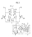
- the second exemplary embodiment shown in FIG. 2 largely corresponds to the first exemplary embodiment.
- the same or equivalent components are provided with the same reference numerals and are not described again.
- a Zener diode 30 is now connected in parallel with the capacitor 22 as a protective circuit for protecting the transistors 16, 19 against impermissible inverse voltage.
- the resistor 18 connected between the summation terminal 21 and ground is still connected in the same way, but is now in an evaluation circuit 32 which is connected to the summation terminal 21.
- the terminal 21 has an input via an analog / digital converter (A / D converter) 33 a microcomputer 34 connected. Furthermore, the terminal 21 is also connected to an input of the A / D converter 33 via an integrator 35. Control outputs of the microcomputer 34 control a control lamp 36 and six control switches 37 which interrupt the respective control signals for the corresponding injection valves (not shown) in order to interrupt the fuel supply to the six cylinders of an Otto engine.
- the number of control switches 37 is of course only exemplary, since in principle any number of injection valves for multi-cylinder internal combustion engines can be controlled.
- the microcomputer 37 can act on the integrator 35 via a line 38.
- the microcomputer 34 can be connected in a conventional manner to further components, assemblies or peripheral devices via a data bus 39.
- a signal corresponding to the ignition and combustion voltage is generated at the summation terminal 21, the contour, level and duration of which depend on the respective combustion process or ignition process.
- an ideal combustion process has a specific signal curve that is stored in the microcomputer 34.
- the spark combustion signals that occur in succession at the summation terminal 21 are then recorded sequentially and in a time-controlled manner and compared with the ideal signal.
- a tolerance band can be defined which characterizes a still sufficient ignition process, with an excess indicating a missing or bad ignition process. If one is recognized, the control computer 36 is switched on by the microcomputer 34 and the fuel supply to the relevant cylinder is switched off. Of course, this can also be done in stages, that is, when a first tolerance limit is exceeded, the indicator light 36 is switched on and only after a Another criterion, for example a further tolerance level, is used to switch off the fuel.
- the signal sequences at the summation terminal 21 can also be evaluated in a simpler manner, for example by only the levels or only the signal lengths can be checked. Such a simpler check can make the use of a microcomputer unnecessary.
- the voltage signals can be integrated at the summation terminal 21 by the integrator, as a result of which the combustion energy can be detected. This can also be used as an alternative or as an additional criterion for the detection of good combustion. In principle, only the value of the result needs to be compared with a standardized value, but of course the integral course can also be checked.
- the integrator 35 can of course also be a component of the microcomputer 34, or can be implemented as a function therein.
Landscapes
- Engineering & Computer Science (AREA)
- Chemical & Material Sciences (AREA)
- Combustion & Propulsion (AREA)
- Mechanical Engineering (AREA)
- General Engineering & Computer Science (AREA)
- Combined Controls Of Internal Combustion Engines (AREA)
- Ignition Installations For Internal Combustion Engines (AREA)
Applications Claiming Priority (2)
| Application Number | Priority Date | Filing Date | Title |
|---|---|---|---|
| DE3924130 | 1989-07-20 | ||
| DE3924130A DE3924130A1 (de) | 1989-07-20 | 1989-07-20 | Vorrichtung zur erkennung fehlender oder schlechter verbrennungen in otto-motoren |
Publications (3)
| Publication Number | Publication Date |
|---|---|
| EP0408916A2 true EP0408916A2 (fr) | 1991-01-23 |
| EP0408916A3 EP0408916A3 (en) | 1992-02-19 |
| EP0408916B1 EP0408916B1 (fr) | 1996-09-18 |
Family
ID=6385522
Family Applications (1)
| Application Number | Title | Priority Date | Filing Date |
|---|---|---|---|
| EP90111724A Expired - Lifetime EP0408916B1 (fr) | 1989-07-20 | 1990-06-21 | Installation pour la détection d'absence de combustion ou de combustion défectueuse dans un moteur à combustion |
Country Status (3)
| Country | Link |
|---|---|
| US (1) | US5045796A (fr) |
| EP (1) | EP0408916B1 (fr) |
| DE (2) | DE3924130A1 (fr) |
Cited By (1)
| Publication number | Priority date | Publication date | Assignee | Title |
|---|---|---|---|---|
| WO1992010673A1 (fr) * | 1990-12-10 | 1992-06-25 | Robert Bosch Gmbh | Systeme d'allumage pour moteurs a combustion interne |
Families Citing this family (12)
| Publication number | Priority date | Publication date | Assignee | Title |
|---|---|---|---|---|
| DE4020986C2 (de) * | 1990-07-02 | 1998-09-03 | Telefunken Microelectron | Elektronisches Zündsystem für eine Brennkraftmaschine |
| DE59007572D1 (de) * | 1990-08-06 | 1994-12-01 | Siemens Ag | Zündeinrichtung für Brennkraftmaschinen. |
| DE4040236A1 (de) * | 1990-12-15 | 1992-06-17 | Bosch Gmbh Robert | Vorrichtung zum erfassen von signalen |
| DE4129292C2 (de) * | 1991-09-03 | 1993-12-02 | Daimler Benz Ag | Verfahren zur Erkennung von Zündfehlfunktionen |
| US5190013A (en) * | 1992-01-10 | 1993-03-02 | Siemens Automotive L.P. | Engine intake valve selective deactivation system and method |
| US5493496A (en) * | 1992-12-15 | 1996-02-20 | Ford Motor Company | Cylinder number identification on a distributorless ignition system engine lacking CID |
| US5392641A (en) * | 1993-03-08 | 1995-02-28 | Chrysler Corporation | Ionization misfire detection apparatus and method for an internal combustion engine |
| US5321978A (en) * | 1993-04-05 | 1994-06-21 | Ford Motor Company | Method and apparatus for detecting cylinder misfire in an internal combustion engine |
| GB9316236D0 (en) * | 1993-08-05 | 1993-09-22 | Bowery William M | Cat guard-catalytic converter protection |
| JP3194676B2 (ja) * | 1994-11-08 | 2001-07-30 | 三菱電機株式会社 | 内燃機関の失火検出装置 |
| DE19630305A1 (de) * | 1996-07-26 | 1998-01-29 | Bosch Gmbh Robert | Schaltungsanordnung zur Messung der Zündspulenprimärspannung einer Zündanlage einer Brennkraftmaschine |
| DE10133005B4 (de) * | 2001-07-06 | 2014-10-23 | Volkswagen Ag | Verfahren und Vorrichtung zum Erkennen der Unterbrechung der Spannungsversorgung einer Zündspule |
Citations (3)
| Publication number | Priority date | Publication date | Assignee | Title |
|---|---|---|---|---|
| GB2172115A (en) * | 1985-03-07 | 1986-09-10 | Fki Crypton Limited | Ignition analysers |
| JPS63295840A (ja) * | 1987-05-26 | 1988-12-02 | Mitsubishi Electric Corp | エンジン制御装置 |
| EP0344349A1 (fr) * | 1988-06-03 | 1989-12-06 | Robert Bosch Gmbh | Détection d'un défaut d'allumage dans les moteurs à allumage par étincelles |
Family Cites Families (7)
| Publication number | Priority date | Publication date | Assignee | Title |
|---|---|---|---|---|
| US2335780A (en) * | 1941-08-19 | 1943-11-30 | Mccoy Charles Wilson | Testing apparatus |
| DE2759155C2 (de) * | 1977-12-31 | 1986-04-03 | Robert Bosch Gmbh, 7000 Stuttgart | Schaltungsanordnung zur Erfassung der Funkendauer in Zündeinrichtungen für Brennkraftmaschinen |
| JPS5751960A (en) * | 1980-09-11 | 1982-03-27 | Nippon Soken Inc | Ignition system diagnostic apparatus for internal combustion engine |
| DE3430000A1 (de) * | 1984-08-16 | 1986-02-27 | Robert Bosch Gmbh, 7000 Stuttgart | Vorrichtung zur auswertung von klopfsignalen |
| GB8505875D0 (en) * | 1985-03-07 | 1985-04-11 | Ti Crypton Ltd | Engine analysers |
| KR920000053B1 (ko) * | 1987-05-26 | 1992-01-06 | 미쓰비시전기 주식회사 | 엔진 제어장치 |
| US4918389A (en) * | 1988-06-03 | 1990-04-17 | Robert Bosch Gmbh | Detecting misfiring in spark ignition engines |
-
1989
- 1989-07-20 DE DE3924130A patent/DE3924130A1/de not_active Ceased
-
1990
- 1990-06-21 DE DE59010505T patent/DE59010505D1/de not_active Expired - Fee Related
- 1990-06-21 EP EP90111724A patent/EP0408916B1/fr not_active Expired - Lifetime
- 1990-06-29 US US07/547,056 patent/US5045796A/en not_active Expired - Lifetime
Patent Citations (3)
| Publication number | Priority date | Publication date | Assignee | Title |
|---|---|---|---|---|
| GB2172115A (en) * | 1985-03-07 | 1986-09-10 | Fki Crypton Limited | Ignition analysers |
| JPS63295840A (ja) * | 1987-05-26 | 1988-12-02 | Mitsubishi Electric Corp | エンジン制御装置 |
| EP0344349A1 (fr) * | 1988-06-03 | 1989-12-06 | Robert Bosch Gmbh | Détection d'un défaut d'allumage dans les moteurs à allumage par étincelles |
Non-Patent Citations (1)
| Title |
|---|
| PATENT ABSTRACTS OF JAPAN vol. 143, no. 122 (M-807)27. März 1989 & JP-A-63 295 840 ( MITSUBISHI ELECTRIC CORP. ) 2. Dezember 1988 * |
Cited By (2)
| Publication number | Priority date | Publication date | Assignee | Title |
|---|---|---|---|---|
| WO1992010673A1 (fr) * | 1990-12-10 | 1992-06-25 | Robert Bosch Gmbh | Systeme d'allumage pour moteurs a combustion interne |
| US5438268A (en) * | 1990-12-10 | 1995-08-01 | Robert Bosch Gmbh | Ignition system for detecting arc voltage of spark plug |
Also Published As
| Publication number | Publication date |
|---|---|
| US5045796A (en) | 1991-09-03 |
| DE3924130A1 (de) | 1991-01-31 |
| EP0408916A3 (en) | 1992-02-19 |
| DE59010505D1 (de) | 1996-10-24 |
| EP0408916B1 (fr) | 1996-09-18 |
Similar Documents
| Publication | Publication Date | Title |
|---|---|---|
| DE4324863C2 (de) | Schaltungsanordnung zur Flammerkennung | |
| EP0408916B1 (fr) | Installation pour la détection d'absence de combustion ou de combustion défectueuse dans un moteur à combustion | |
| DE3934310C2 (de) | Verbrennungsaussetzer-Erkennungsvorrichtung für eine Mehrzylinder-Brennkraftmaschine | |
| EP0016218B1 (fr) | Dispositif pour commander dans des machines motrices a combustion des operations qui dependent de parametres de fonctionnement et se repetent | |
| DE4138823C2 (de) | Vorrichtung zur Erfassung eines Ionenstroms | |
| DE4133015C2 (de) | Zündsystem für Mehrzylinder-Verbrennungsmotoren | |
| DE10012854B4 (de) | Verbrennungszustands-Detektionsgerät für Verbrennungsmotor | |
| DE2307443A1 (de) | Zuendkontrollsystem | |
| DE4239592A1 (fr) | ||
| EP1222385A1 (fr) | Dispositif et procede d'allumage pour moteur a combustion interne | |
| EP1476648A1 (fr) | Procede et dispositif de reconnaissance d'une phase d'un moteur a allumage commande a 4 temps | |
| DE4239803C2 (de) | Ionisationsstromdetektoreinrichtung für eine Brennkraftmaschine | |
| DE19648951C2 (de) | Fehlzündungserfasserungsvorrichtung für einen Verbrennungsmotor | |
| DE4020986C2 (de) | Elektronisches Zündsystem für eine Brennkraftmaschine | |
| DE3735234C2 (de) | Zündüberwachungseinrichtung zur Erkennung von Zündaussetzern in einer Zündanlage für einen Verbrennungsmotor für ein Kraftfahrzeug | |
| EP0635638B1 (fr) | Circuit de détection de flamme | |
| DE112018008224T5 (de) | Ionenstrom-Detektionsschaltung, Zündsteuerungsgerät und Zündsystem | |
| EP0502549B1 (fr) | Dispositif de surveillance de l'étincelle dans une installation d'allumage | |
| DE2335562A1 (de) | Schaltungsanordnung zur erzeugung einer triggeraustastspannung bei der analyse des zuendspannungsverlaufes von brennkraftmaschinen | |
| DE4305197A1 (en) | Ignition circuit with over-current protection e.g. for IC engine - has current-limiting circuit to separate transistor circuit for each coil monitored via common supply resistor and op. amp. control to limit current to set levels. | |
| EP1003967B1 (fr) | Dispositif de mesure et de diagnostic pour le systeme d'allumage d'un moteur a combustion interne | |
| EP0747595B1 (fr) | Dispositif et méthode de détection d'allumage | |
| EP0615580B1 (fr) | Systeme d'allumage a limitation de la tension primaire et a diagnostic de defauts | |
| DE19956381A1 (de) | Vorrichtung und Verfahren zur Zündung einer Brennkraftmaschine | |
| DE1539232C (de) | Zündvorrichtung fur Brennkraft maschinen |
Legal Events
| Date | Code | Title | Description |
|---|---|---|---|
| PUAI | Public reference made under article 153(3) epc to a published international application that has entered the european phase |
Free format text: ORIGINAL CODE: 0009012 |
|
| AK | Designated contracting states |
Kind code of ref document: A2 Designated state(s): DE FR IT SE |
|
| PUAL | Search report despatched |
Free format text: ORIGINAL CODE: 0009013 |
|
| AK | Designated contracting states |
Kind code of ref document: A3 Designated state(s): DE FR IT SE |
|
| RAP3 | Party data changed (applicant data changed or rights of an application transferred) |
Owner name: ROBERT BOSCH GMBH |
|
| 17P | Request for examination filed |
Effective date: 19920716 |
|
| 17Q | First examination report despatched |
Effective date: 19950606 |
|
| GRAG | Despatch of communication of intention to grant |
Free format text: ORIGINAL CODE: EPIDOS AGRA |
|
| GRAH | Despatch of communication of intention to grant a patent |
Free format text: ORIGINAL CODE: EPIDOS IGRA |
|
| GRAH | Despatch of communication of intention to grant a patent |
Free format text: ORIGINAL CODE: EPIDOS IGRA |
|
| GRAA | (expected) grant |
Free format text: ORIGINAL CODE: 0009210 |
|
| AK | Designated contracting states |
Kind code of ref document: B1 Designated state(s): DE FR IT SE |
|
| ET | Fr: translation filed | ||
| REF | Corresponds to: |
Ref document number: 59010505 Country of ref document: DE Date of ref document: 19961024 |
|
| ET | Fr: translation filed | ||
| ITF | It: translation for a ep patent filed |
Owner name: STUDIO JAUMANN |
|
| PLBE | No opposition filed within time limit |
Free format text: ORIGINAL CODE: 0009261 |
|
| STAA | Information on the status of an ep patent application or granted ep patent |
Free format text: STATUS: NO OPPOSITION FILED WITHIN TIME LIMIT |
|
| 26N | No opposition filed | ||
| PGFP | Annual fee paid to national office [announced via postgrant information from national office to epo] |
Ref country code: FR Payment date: 20020622 Year of fee payment: 13 |
|
| PGFP | Annual fee paid to national office [announced via postgrant information from national office to epo] |
Ref country code: SE Payment date: 20020626 Year of fee payment: 13 |
|
| PGFP | Annual fee paid to national office [announced via postgrant information from national office to epo] |
Ref country code: DE Payment date: 20020802 Year of fee payment: 13 |
|
| PG25 | Lapsed in a contracting state [announced via postgrant information from national office to epo] |
Ref country code: SE Free format text: LAPSE BECAUSE OF NON-PAYMENT OF DUE FEES Effective date: 20030622 |
|
| PG25 | Lapsed in a contracting state [announced via postgrant information from national office to epo] |
Ref country code: DE Free format text: LAPSE BECAUSE OF NON-PAYMENT OF DUE FEES Effective date: 20040101 |
|
| EUG | Se: european patent has lapsed | ||
| PG25 | Lapsed in a contracting state [announced via postgrant information from national office to epo] |
Ref country code: FR Free format text: LAPSE BECAUSE OF NON-PAYMENT OF DUE FEES Effective date: 20040227 |
|
| REG | Reference to a national code |
Ref country code: FR Ref legal event code: ST |
|
| PG25 | Lapsed in a contracting state [announced via postgrant information from national office to epo] |
Ref country code: IT Free format text: LAPSE BECAUSE OF NON-PAYMENT OF DUE FEES;WARNING: LAPSES OF ITALIAN PATENTS WITH EFFECTIVE DATE BEFORE 2007 MAY HAVE OCCURRED AT ANY TIME BEFORE 2007. THE CORRECT EFFECTIVE DATE MAY BE DIFFERENT FROM THE ONE RECORDED. Effective date: 20050621 |