EP0635638B1 - Circuit de détection de flamme - Google Patents
Circuit de détection de flamme Download PDFInfo
- Publication number
- EP0635638B1 EP0635638B1 EP94109218A EP94109218A EP0635638B1 EP 0635638 B1 EP0635638 B1 EP 0635638B1 EP 94109218 A EP94109218 A EP 94109218A EP 94109218 A EP94109218 A EP 94109218A EP 0635638 B1 EP0635638 B1 EP 0635638B1
- Authority
- EP
- European Patent Office
- Prior art keywords
- ignition
- signal
- circuit
- flame
- comparator
- Prior art date
- Legal status (The legal status is an assumption and is not a legal conclusion. Google has not performed a legal analysis and makes no representation as to the accuracy of the status listed.)
- Expired - Lifetime
Links
Images


Classifications
-
- F—MECHANICAL ENGINEERING; LIGHTING; HEATING; WEAPONS; BLASTING
- F23—COMBUSTION APPARATUS; COMBUSTION PROCESSES
- F23Q—IGNITION; EXTINGUISHING-DEVICES
- F23Q3/00—Igniters using electrically-produced sparks
- F23Q3/004—Using semiconductor elements
-
- F—MECHANICAL ENGINEERING; LIGHTING; HEATING; WEAPONS; BLASTING
- F02—COMBUSTION ENGINES; HOT-GAS OR COMBUSTION-PRODUCT ENGINE PLANTS
- F02P—IGNITION, OTHER THAN COMPRESSION IGNITION, FOR INTERNAL-COMBUSTION ENGINES; TESTING OF IGNITION TIMING IN COMPRESSION-IGNITION ENGINES
- F02P17/00—Testing of ignition installations, e.g. in combination with adjusting; Testing of ignition timing in compression-ignition engines
- F02P17/12—Testing characteristics of the spark, ignition voltage or current
-
- F—MECHANICAL ENGINEERING; LIGHTING; HEATING; WEAPONS; BLASTING
- F02—COMBUSTION ENGINES; HOT-GAS OR COMBUSTION-PRODUCT ENGINE PLANTS
- F02P—IGNITION, OTHER THAN COMPRESSION IGNITION, FOR INTERNAL-COMBUSTION ENGINES; TESTING OF IGNITION TIMING IN COMPRESSION-IGNITION ENGINES
- F02P3/00—Other installations
- F02P3/02—Other installations having inductive energy storage, e.g. arrangements of induction coils
- F02P3/04—Layout of circuits
- F02P3/05—Layout of circuits for control of the magnitude of the current in the ignition coil
- F02P3/051—Opening or closing the primary coil circuit with semiconductor devices
- F02P3/053—Opening or closing the primary coil circuit with semiconductor devices using digital techniques
-
- F—MECHANICAL ENGINEERING; LIGHTING; HEATING; WEAPONS; BLASTING
- F23—COMBUSTION APPARATUS; COMBUSTION PROCESSES
- F23N—REGULATING OR CONTROLLING COMBUSTION
- F23N5/00—Systems for controlling combustion
- F23N5/02—Systems for controlling combustion using devices responsive to thermal changes or to thermal expansion of a medium
- F23N5/12—Systems for controlling combustion using devices responsive to thermal changes or to thermal expansion of a medium using ionisation-sensitive elements, i.e. flame rods
- F23N5/123—Systems for controlling combustion using devices responsive to thermal changes or to thermal expansion of a medium using ionisation-sensitive elements, i.e. flame rods using electronic means
-
- F—MECHANICAL ENGINEERING; LIGHTING; HEATING; WEAPONS; BLASTING
- F02—COMBUSTION ENGINES; HOT-GAS OR COMBUSTION-PRODUCT ENGINE PLANTS
- F02P—IGNITION, OTHER THAN COMPRESSION IGNITION, FOR INTERNAL-COMBUSTION ENGINES; TESTING OF IGNITION TIMING IN COMPRESSION-IGNITION ENGINES
- F02P17/00—Testing of ignition installations, e.g. in combination with adjusting; Testing of ignition timing in compression-ignition engines
- F02P17/12—Testing characteristics of the spark, ignition voltage or current
- F02P2017/123—Generating additional sparks for diagnostics
-
- F—MECHANICAL ENGINEERING; LIGHTING; HEATING; WEAPONS; BLASTING
- F02—COMBUSTION ENGINES; HOT-GAS OR COMBUSTION-PRODUCT ENGINE PLANTS
- F02P—IGNITION, OTHER THAN COMPRESSION IGNITION, FOR INTERNAL-COMBUSTION ENGINES; TESTING OF IGNITION TIMING IN COMPRESSION-IGNITION ENGINES
- F02P17/00—Testing of ignition installations, e.g. in combination with adjusting; Testing of ignition timing in compression-ignition engines
- F02P17/12—Testing characteristics of the spark, ignition voltage or current
- F02P2017/125—Measuring ionisation of combustion gas, e.g. by using ignition circuits
- F02P2017/126—Measuring ionisation of combustion gas, e.g. by using ignition circuits for burners
-
- F—MECHANICAL ENGINEERING; LIGHTING; HEATING; WEAPONS; BLASTING
- F23—COMBUSTION APPARATUS; COMBUSTION PROCESSES
- F23N—REGULATING OR CONTROLLING COMBUSTION
- F23N2223/00—Signal processing; Details thereof
- F23N2223/22—Timing network
-
- F—MECHANICAL ENGINEERING; LIGHTING; HEATING; WEAPONS; BLASTING
- F23—COMBUSTION APPARATUS; COMBUSTION PROCESSES
- F23N—REGULATING OR CONTROLLING COMBUSTION
- F23N2227/00—Ignition or checking
- F23N2227/36—Spark ignition, e.g. by means of a high voltage
Definitions
- the invention relates to a circuit arrangement for Flame detection for a transistor coil ignition of a burner, which has a control stage, one in the circuit the primary winding of an ignition coil located power transistor when a certain current is reached locks in the circuit of the primary winding, the secondary winding lies over a spark gap and the specific one Current strength is selected so that when the power transistor is blocked voltage induced in the secondary winding triggers an ignition spark over a spark gap.
- a transistor coil ignition is used as an ignition device with Gas, diesel fuel, gasoline or other fuels operated burners provided. It is desirable that Monitor burner flame, i.e. a flame detection and To provide ignition diagnosis.
- DE-OS 4107335 is also a method and a device for ignition monitoring of an ignition system known with which the ignition system on shunt and interruption checked on the secondary high voltage side can be. For this purpose, an ignition diagnosis is made in the ignition phase carried out.
- US-A-4 557 236 further describes an internal combustion engine the one to save fuel with a lean Air fuel mixture is operated, and at the Measurement of the flame speed the ionization height in the Cylinder is detected. If misfiring occurs, it will Air-fuel mixture enriched until stable is achieved. A second spark is also used for this used and thus the measurement signal on the secondary that is called the high voltage side of the coil removed.
- the object underlying the invention is in contrast, in the circuit arrangement of the beginning mentioned type so that reliable detection of Flame possible with less circuitry effort is.
- the training specified in claim 6 allows additional diagnosis to detect shunt and interruption and short circuit of the ignition system in the ignition phase in addition to the flame detection in the flame detection phase.
- Fig. 1 is a conventional in a block diagram Transistor coil ignition shown with a Embodiment of the circuit arrangement according to the Flame detection is provided.
- the transistor coil ignition consists of an ignition coil ZS, a power transistor Tr2 with a Zener diode ZD1 Voltage limitation and a current sensor R2 for current detection.
- the control stage of the transistor coil ignition is at the embodiment shown in Fig. 1 from a Comparator K1 formed, at one input one of two Current setpoints Isoll1 and Isoll2 are those for the control during any ignition phase and during one serve any flame detection phase.
- the respective Periods for these two phases are by a timer ZG1 determined that a switch S1 with two contacts for the two Current setpoints switches so that depending on the switch position corresponding current setpoint is at the input of comparator K1. Because of this training is a simultaneous ignition and Flame detection not possible.
- the actual current value is at the second input of the comparator K1 of the primary winding of the ignition coil ZS switched through power transistor Tr2 flowing current is detected by the current sensor R2, which is in the form of a resistor Has.
- the comparator K1 controls a flip-flop FF1 with one Clock input CP, whose non-inverting output Q at one Driver stage, in the present case from switched in push-pull Transistors Tr1a and Tr1b.
- the power transistor Tr2 is controlled via the driver stage to the primary winding of the To load ignition coil ZS.
- the current setpoint Isoll1 lies, so that the current flow over the primary winding of the Ignition coil ZS is sufficient to lock the power transistor Tr2 an ignition spark at the spark gap FS, i.e. to the To produce electrodes or the spark plug is in the Flame detection phase of the current setpoint Isoll2 at comparator K1, which is below the current setpoint Isoll1 and for a current flow about the primary winding of the ignition coil ZS, which so far is reduced that there is no sparkover at the electrodes non-conductive media e.g. Air or a gas mixture can.
- non-conductive media e.g. Air or a gas mixture can.
- the spark gap FS is ionized and thus in a conductive state, so that there is still a sparkover occurs because no ionization work by the voltage at the Spark gap FS must be performed.
- the amplitude of the on the secondary side of the ignition coil ZS, i.e. pulses occurring at the spark gap FS should be in Dependence on the length of the spark gap FS i.e. of Electrode distance and / or the flow rate of the Gas mixture and / or the flame speed set will. At higher speeds there is one Widening of the ionization channel, which increases the Electrode distance compared to the conditions when stationary Gas mixture corresponds.
- This setting can be made via a corresponding choice of the amount of the value IS0ll2 on the comparator K1 done, for example, by means of a variable voltage supplying generator, for example a ramp generator instead of switch S1 is possible.
- a flashover is caused by a flame detection device monitors that according to FIG. 1 from a rectifier Glr1, a memory element in the form of an RC element R3, C2 and a comparator K2, which the signal from the Primary winding of the ignition coil ZS after locking the Power transistor Tr2 on the presence of a flame in the Evaluates flame detection phase.
- the signal present at the cathode of the diode D1 is integrated via the RC element R3, C2 and via the comparator K2 by means of a comparison with one at the other entrance of the Comparator K2 lying setpoint evaluated.
- a ZüD1 ignition diagnosis device can also be provided be in the ignition phase the ignition system on shunt and Interruption checked on the secondary high voltage side.
- Such an ignition diagnosis device is known per se.
- the comparator When the battery voltage + Ub is switched on, the comparator is connected K1 is the reference value Isoll1. That means the ignition is in the ignition phase, the duration of which by the timer ZG1 is determined. In this ignition phase there is a next to the ignition Simultaneous ignition diagnosis via the ZüD1 ignition diagnosis device so that the spark gap FS on interruptions and shunts of the electrodes is examined.
- the timing element ZG1 switches over the switch S1 the reference value Isoll2 to the comparator K1.
- the primary charging current detected by the current sensor R2 Ignition coil ZS reduced so far that the spark gap FS without Flame no flashover can occur.
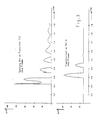
- points A and B in 1 are then signals with that in FIG. 2 shown course.
- this can be done in the presence of a flame occurring load of the ignition coil ZS by a Arcing at the spark gap FS as a result of not explain ionizing work, so that the Energy requirement for the sparkover is much lower than for non-ionized and non-conductive media such as Air or other gas mixtures.
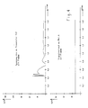
- Switch-off voltage values at transistor Tr2 are no pulses at point A and at diode D1, as shown in FIG. 4 is shown.
- the signal present at point A with or without pulse peaks (Fig. 3, Fig. 4) is rectified via the rectifier Glr1 and smoothed over the integrator R3, C2.
- the smoothed Voltage is at the comparator K2, which this with a Reference voltage USOLL is compared.
- the comparator K2 which too a corresponding display on the display device A1 leads.
- the error signal thus formed can be used for further processing be used.
- Fig. 5 shows the schematic diagram of another Embodiment of the circuit arrangement according to the invention, that of the embodiment shown in Fig. 1 for distinguishes one by the design of the circuit device, those in the flame detection phase over the Primary winding of the ignition coil ZS flowing charging current on a Amperage limited below that for generating a Spark is in the ignition phase necessary charging current. While this in the embodiment shown in Fig. 1 Circuit device from a timer ZG and one by Timer ZG operated switch S1 existed at the in Fig. 5 embodiment shown this circuit device formed by a ramp generator RG1, the output voltage is in the form of a value Irp on the comparator K1.
- the embodiment shown in Fig. 5 Circuit arrangement according to the invention differs further from the embodiment shown in Fig. 1 in that the value I is i.e. the actual current value of the over the Primary winding of the ignition coil ZS with the power transistor switched on Tr2 flowing current not only at the entrance of the Comparator K1 but also on a signal evaluation device trained display device A1.
- the embodiment shown in Fig. 5 is particular suitable for the amplitude of the flame detection pulses a statement about the flow velocity of the flame or the gas mixture in the combustion chamber.
- the Spark gap FS pulses switched with increasing voltage amplitude. This is achieved via the ramp generator RG1, whose Output voltage increases linearly with time.
- the primary charging current Iact that flows through resistor R2, which works as a current sensor, then pulses on the secondary side of the ignition coil ZS increasing amplitude generated. Since the ionization channel, i.e. the actual spark gap FS at higher speeds of the Gas mixture or increases at higher flame speeds, provides the level of the amplitude of the pulses on the spark gap FS, which is necessary to cause a rollover, a Information about the flame or gas mixture speed.
- the evaluation circuit delivers from the rectifier Glrl, the integration element R3, C2 via the comparator K2 Signal Uout, which is located on the display device A1.
- the value of the Primary charging current I which is d. H. to that Time at which the signal Uout occurs at the comparator K2 is also due to the display device A1.
- the display device A1 is like this as a signal processing device trained that the input values stored and as a measure for the speed of the flame or the gas mixture is evaluated and can be used.
- Circuit arrangement according to the invention offers compared to the in Fig. 1 thus illustrate the further embodiment Possibility not only to carry out a flame detection but also also information about the speed of the flame or of the gas mixture to be ignited.
Claims (6)
- Agencement de circuiterie de détection de flamme, destiné à un allumage de brûleur à bobine et à transistor, qui comporte un étage de commande qui bloque un transistor de puissance situé dans le circuit de l'enroulement primaire d'une bobine d'allumage lorsqu'une intensité déterminée de courant est atteinte dans le circuit de l'enroulement primaire, l'enroulement secondaire étant situé sur un trajet d'étincelle, et l'intensité déterminée de courant étant choisie d'une manière telle que la tension induite dans renroulement secondaire lors du blocage du transistor de puissance déclenche une étincelle d'allumage sur le trajet d'étincelle, caractérisé par:un dispositif commutateur (S1, ZG1; RG1), disposé dans l'étage de commande (K1, FF1, Tr1a, Tr1b), qui réduit, dans la phase de détection de flamme dans laquelle le transistor de puissance (Tr2) est bloqué, l'intensité du courant dans le circuit de l'enroulement secondaire de la bobine d'allumage (ZS) à une valeur à laquelle la tension alors induite dans l'enroulement secondaire de la bobine d'allumage (ZS) ne conduit à un éclatement d'étincelle dans le trajet d'étincelle (FS) que lorsqu'une flamme est présente, et

- Agencement de circuiterie selon la revendication 1, caractérisé en ce que le dispositif de commutation (ZG1, S1) se compose d'un relais temporisateur (ZG1) et d'un commutateur (RG1) qui est actionné par le relais temporisateur (ZG1) et qui applique selon la position du commutateur la valeur d'intensité de courant, appropriée à la détection de flamme ou à l'allumage, à une entrée d'un comparateur (K1), inclus dans l'étage de commande de l'allumage à bobine et à transistor, à l'autre entrée duquel est appliquée la valeur d'intensité de courant d'un capteur (R2) de courant inclus dans le circuit de l'enroulement primaire de la bobine d'allumage (ZS).
- Agencement de circuiterie selon la revendication 1, caractérisé en ce que le dispositif de commutation (RG1) se compose d'un générateur de rampe qui produit une tension de sortie à croissance linéaire qui est appliquée à l'entrée d'un comparateur (K1), inclus dans l'étage de commande de l'allumage à bobine et à transistor, à l'autre entrée duquel est appliquée la valeur d'intensité de courant d'un capteur (R2) de courant inclus dans le circuit de l'enroulement primaire de la bobine d'allumage (ZS), cette valeur d'intensité de courant du capteur (R2) de courant étant appliquée, ainsi que le signal d'indication de la circuiterie d'évaluation (Glr1, R3, C2, K2) à une circuiterie de traitement (A1) de signaux qui produit une indication correspondant au signal d'indication et qui traite les signaux d'entrée pour fournir une mesure de la vitesse de la flamme et/ou de la vitesse du mélange de gaz de combustion.
- Agencement de circuiterie selon la revendication 1, 2 ou 3, caractérisé en ce que la circuiterie d'évaluation (Glr1, R3, C2, K2) comporte un autre comparateur (K2) qui compare à une valeur de référence le signal provenant de l'enroulement primaire de la bobine d'allumage (ZS), intégré au moyen d'un redresseur (Glr1) et d'un intégrateur (R3, C2), et qui envoie un signal correspondant à la comparaison.
- Agencement de circuiterie selon la revendication 4, caractérisé en ce que le signal de sortie de l'autre comparateur (K2) est appliqué à un dispositif indicateur, ou d'affichage, (A1)
- Agencement de circuiterie selon la revendication 4, caractérisé en ce que par un dispositif de diagnostic (ZüD1) d'allumage dont le signal de sortie est appliqué au dispositif indicateur ou d'affichage (A1).
Applications Claiming Priority (3)
| Application Number | Priority Date | Filing Date | Title |
|---|---|---|---|
| DE9311065U DE9311065U1 (de) | 1993-07-23 | 1993-07-23 | Schaltungsanordnung zur Flammerkennung |
| DE4324863 | 1993-07-23 | ||
| DE4324863A DE4324863C2 (de) | 1993-07-23 | 1993-07-23 | Schaltungsanordnung zur Flammerkennung |
Publications (3)
| Publication Number | Publication Date |
|---|---|
| EP0635638A2 EP0635638A2 (fr) | 1995-01-25 |
| EP0635638A3 EP0635638A3 (fr) | 1995-06-21 |
| EP0635638B1 true EP0635638B1 (fr) | 1998-11-25 |
Family
ID=25927979
Family Applications (1)
| Application Number | Title | Priority Date | Filing Date |
|---|---|---|---|
| EP94109218A Expired - Lifetime EP0635638B1 (fr) | 1993-07-23 | 1994-06-15 | Circuit de détection de flamme |
Country Status (2)
| Country | Link |
|---|---|
| EP (1) | EP0635638B1 (fr) |
| DE (1) | DE9311065U1 (fr) |
Families Citing this family (6)
| Publication number | Priority date | Publication date | Assignee | Title |
|---|---|---|---|---|
| US5406921A (en) * | 1993-11-08 | 1995-04-18 | Chrysler Corporation | Misfire detection method |
| US5526788A (en) * | 1993-11-08 | 1996-06-18 | Chrysler Corporation | Auto-ignition detection method |
| FR2717534B1 (fr) * | 1994-03-17 | 1996-05-15 | Eyquem | Générateur d'allumage haute énergie notamment pour turbine à gaz. |
| DE102009046097B9 (de) * | 2009-10-28 | 2013-08-08 | Aev Energy Gmbh | Verbrennungsmotorüberwachungsverfahren und -vorrichtung |
| DE102011100510B4 (de) * | 2011-04-28 | 2014-02-13 | Aev Energy Gmbh | Verbrennungsmotorüberwachungsverfahren und -vorrichtung |
| CN109780569B (zh) * | 2019-01-25 | 2020-06-26 | 珠海格力电器股份有限公司 | 基于Buck原理的脉冲点火电路和燃气壁挂炉 |
Family Cites Families (4)
| Publication number | Priority date | Publication date | Assignee | Title |
|---|---|---|---|---|
| FR2347620A1 (fr) * | 1976-07-15 | 1977-11-04 | Bicosa Recherches | Dispositif de detection de flamme ou d'etincelle et organe d'allumage d'un gaz combustible |
| US4557236A (en) * | 1983-12-29 | 1985-12-10 | Automotive Engine Associates | Combustion roughness servo control to control fuel/air metering or EGR metering to an internal combustion engine |
| US5111790A (en) * | 1990-09-28 | 1992-05-12 | Prestolite Wire Corporation | Direct fire ignition system having individual knock detection sensor |
| FR2676506B1 (fr) * | 1991-05-15 | 1993-09-03 | Siemens Automotive Sa | Procede et dispositif de detection de rates d'allumage dans un cylindre de moteur a combustion interne et leur application. |
-
1993
- 1993-07-23 DE DE9311065U patent/DE9311065U1/de not_active Expired - Lifetime
-
1994
- 1994-06-15 EP EP94109218A patent/EP0635638B1/fr not_active Expired - Lifetime
Also Published As
| Publication number | Publication date |
|---|---|
| DE9311065U1 (de) | 1993-09-09 |
| EP0635638A3 (fr) | 1995-06-21 |
| EP0635638A2 (fr) | 1995-01-25 |
Similar Documents
| Publication | Publication Date | Title |
|---|---|---|
| DE4324863C2 (de) | Schaltungsanordnung zur Flammerkennung | |
| DE1928679C3 (de) | Elektrische Schaltungsanordnung zur Prüfung der Zündanlage von Brennkraftmaschinen | |
| DE19514633C2 (de) | Vorrichtung zur Erfassung von Fehlzündungen in einer Brennkraftmaschine | |
| DE4241471C2 (de) | Verbrennungsermittlungsvorrichtung für eine Brennkraftmaschine | |
| DE4204484C2 (de) | Verbrennungsdetektorvorrichtung für eine Brennkraftmaschine | |
| EP0790406A2 (fr) | Système d'allumage électronique pour moteurs à combustion interne | |
| DE10012854B4 (de) | Verbrennungszustands-Detektionsgerät für Verbrennungsmotor | |
| EP0752580B1 (fr) | Circuit de mesure pour courant ionique | |
| EP0752582A2 (fr) | Circuit de mesure pour courant ionique | |
| DE4132858C2 (de) | Steuervorrichtung mit Feldzündungsdetektion für eine Brennkraftmaschine | |
| DE4233224C2 (de) | Vorrichtung zum Erfassen der Verbrennung des Gemisches in einem Zylinder einer Brennkraftmaschine | |
| DE3032659C2 (de) | Zündanlage für Brennkraftmaschinen. | |
| DE10256456A1 (de) | Überwachungsverfahren für einen Aktor und zugehörige Treiberschaltung | |
| EP0389775B1 (fr) | Circuit pour la surveillance de la haute tension dans une installation d'allumage | |
| DE19646917A1 (de) | Vorrichtung zum Erfassen eines Zustands einer Verbrennung in einer Brennkraftmaschine | |
| EP0635638B1 (fr) | Circuit de détection de flamme | |
| DE4239803C2 (de) | Ionisationsstromdetektoreinrichtung für eine Brennkraftmaschine | |
| DE10229848B4 (de) | Feuerungszustandsermittlungssystem für Verbrennungsmotoren | |
| EP0408916A2 (fr) | Installation pour la détection d'absence de combustion ou de combustion défectueuse dans un moteur à combustion | |
| DE19614288C1 (de) | Schaltungsanordnung zur Ionenstrommessung im Verbrennungsraum einer Brennkraftmaschine und zur Wechselstromzündung der Brennkraftmaschine | |
| DE2547397C2 (de) | Elektronisches Zündsystem für Brennkraftmaschinen | |
| EP0502549B1 (fr) | Dispositif de surveillance de l'étincelle dans une installation d'allumage | |
| EP1003967B1 (fr) | Dispositif de mesure et de diagnostic pour le systeme d'allumage d'un moteur a combustion interne | |
| EP0747595B1 (fr) | Dispositif et méthode de détection d'allumage | |
| DE2342373B2 (de) | Kondensator-spulen-zuendanlage fuer brennkraftmaschinen |
Legal Events
| Date | Code | Title | Description |
|---|---|---|---|
| PUAI | Public reference made under article 153(3) epc to a published international application that has entered the european phase |
Free format text: ORIGINAL CODE: 0009012 |
|
| AK | Designated contracting states |
Kind code of ref document: A2 Designated state(s): DE ES FR GB IT SE |
|
| PUAL | Search report despatched |
Free format text: ORIGINAL CODE: 0009013 |
|
| AK | Designated contracting states |
Kind code of ref document: A3 Designated state(s): DE ES FR GB IT SE |
|
| 17P | Request for examination filed |
Effective date: 19950809 |
|
| 17Q | First examination report despatched |
Effective date: 19961205 |
|
| GRAG | Despatch of communication of intention to grant |
Free format text: ORIGINAL CODE: EPIDOS AGRA |
|
| GRAG | Despatch of communication of intention to grant |
Free format text: ORIGINAL CODE: EPIDOS AGRA |
|
| GRAH | Despatch of communication of intention to grant a patent |
Free format text: ORIGINAL CODE: EPIDOS IGRA |
|
| GRAH | Despatch of communication of intention to grant a patent |
Free format text: ORIGINAL CODE: EPIDOS IGRA |
|
| RAP1 | Party data changed (applicant data changed or rights of an application transferred) |
Owner name: BERU AG |
|
| GRAA | (expected) grant |
Free format text: ORIGINAL CODE: 0009210 |
|
| AK | Designated contracting states |
Kind code of ref document: B1 Designated state(s): DE ES FR GB IT SE |
|
| GBT | Gb: translation of ep patent filed (gb section 77(6)(a)/1977) |
Effective date: 19981208 |
|
| REF | Corresponds to: |
Ref document number: 59407327 Country of ref document: DE Date of ref document: 19990107 |
|
| ET | Fr: translation filed | ||
| ITF | It: translation for a ep patent filed |
Owner name: STUDIO TORTA S.R.L. |
|
| REG | Reference to a national code |
Ref country code: ES Ref legal event code: FG2A Ref document number: 2125373 Country of ref document: ES Kind code of ref document: T3 |
|
| PLBE | No opposition filed within time limit |
Free format text: ORIGINAL CODE: 0009261 |
|
| STAA | Information on the status of an ep patent application or granted ep patent |
Free format text: STATUS: NO OPPOSITION FILED WITHIN TIME LIMIT |
|
| 26N | No opposition filed | ||
| REG | Reference to a national code |
Ref country code: GB Ref legal event code: IF02 |
|
| PGFP | Annual fee paid to national office [announced via postgrant information from national office to epo] |
Ref country code: ES Payment date: 20020612 Year of fee payment: 9 |
|
| PGFP | Annual fee paid to national office [announced via postgrant information from national office to epo] |
Ref country code: SE Payment date: 20020620 Year of fee payment: 9 |
|
| PGFP | Annual fee paid to national office [announced via postgrant information from national office to epo] |
Ref country code: FR Payment date: 20020621 Year of fee payment: 9 |
|
| PGFP | Annual fee paid to national office [announced via postgrant information from national office to epo] |
Ref country code: GB Payment date: 20030513 Year of fee payment: 10 |
|
| PG25 | Lapsed in a contracting state [announced via postgrant information from national office to epo] |
Ref country code: SE Free format text: LAPSE BECAUSE OF NON-PAYMENT OF DUE FEES Effective date: 20030616 Ref country code: ES Free format text: LAPSE BECAUSE OF NON-PAYMENT OF DUE FEES Effective date: 20030616 |
|
| EUG | Se: european patent has lapsed | ||
| PG25 | Lapsed in a contracting state [announced via postgrant information from national office to epo] |
Ref country code: FR Free format text: LAPSE BECAUSE OF NON-PAYMENT OF DUE FEES Effective date: 20040227 |
|
| REG | Reference to a national code |
Ref country code: FR Ref legal event code: ST |
|
| PG25 | Lapsed in a contracting state [announced via postgrant information from national office to epo] |
Ref country code: GB Free format text: LAPSE BECAUSE OF NON-PAYMENT OF DUE FEES Effective date: 20040615 |
|
| REG | Reference to a national code |
Ref country code: ES Ref legal event code: FD2A Effective date: 20030616 |
|
| GBPC | Gb: european patent ceased through non-payment of renewal fee |
Effective date: 20040615 |
|
| PG25 | Lapsed in a contracting state [announced via postgrant information from national office to epo] |
Ref country code: IT Free format text: LAPSE BECAUSE OF NON-PAYMENT OF DUE FEES;WARNING: LAPSES OF ITALIAN PATENTS WITH EFFECTIVE DATE BEFORE 2007 MAY HAVE OCCURRED AT ANY TIME BEFORE 2007. THE CORRECT EFFECTIVE DATE MAY BE DIFFERENT FROM THE ONE RECORDED. Effective date: 20050615 |
|
| PGFP | Annual fee paid to national office [announced via postgrant information from national office to epo] |
Ref country code: DE Payment date: 20050630 Year of fee payment: 12 |
|
| PG25 | Lapsed in a contracting state [announced via postgrant information from national office to epo] |
Ref country code: DE Free format text: LAPSE BECAUSE OF NON-PAYMENT OF DUE FEES Effective date: 20070103 |