EP0407652A2 - Aufbauwand mit Entnahmeeinrichtungen für die Intensivmedizin - Google Patents
Aufbauwand mit Entnahmeeinrichtungen für die Intensivmedizin Download PDFInfo
- Publication number
- EP0407652A2 EP0407652A2 EP89117674A EP89117674A EP0407652A2 EP 0407652 A2 EP0407652 A2 EP 0407652A2 EP 89117674 A EP89117674 A EP 89117674A EP 89117674 A EP89117674 A EP 89117674A EP 0407652 A2 EP0407652 A2 EP 0407652A2
- Authority
- EP
- European Patent Office
- Prior art keywords
- wall
- room
- bed
- elements
- channel
- Prior art date
- Legal status (The legal status is an assumption and is not a legal conclusion. Google has not performed a legal analysis and makes no representation as to the accuracy of the status listed.)
- Granted
Links
Images


Classifications
-
- H—ELECTRICITY
- H02—GENERATION; CONVERSION OR DISTRIBUTION OF ELECTRIC POWER
- H02G—INSTALLATION OF ELECTRIC CABLES OR LINES, OR OF COMBINED OPTICAL AND ELECTRIC CABLES OR LINES
- H02G3/00—Installations of electric cables or lines or protective tubing therefor in or on buildings, equivalent structures or vehicles
- H02G3/28—Installations of cables, lines, or separate protective tubing therefor in conduits or ducts pre-established in walls, ceilings or floors
- H02G3/286—Installations of cables, lines, or separate protective tubing therefor in conduits or ducts pre-established in walls, ceilings or floors in walls
-
- E—FIXED CONSTRUCTIONS
- E04—BUILDING
- E04C—STRUCTURAL ELEMENTS; BUILDING MATERIALS
- E04C2/00—Building elements of relatively thin form for the construction of parts of buildings, e.g. sheet materials, slabs, or panels
- E04C2/44—Building elements of relatively thin form for the construction of parts of buildings, e.g. sheet materials, slabs, or panels characterised by the purpose
- E04C2/52—Building elements of relatively thin form for the construction of parts of buildings, e.g. sheet materials, slabs, or panels characterised by the purpose with special adaptations for auxiliary purposes, e.g. serving for locating conduits
- E04C2/521—Building elements of relatively thin form for the construction of parts of buildings, e.g. sheet materials, slabs, or panels characterised by the purpose with special adaptations for auxiliary purposes, e.g. serving for locating conduits serving for locating conduits; for ventilating, heating or cooling
-
- E—FIXED CONSTRUCTIONS
- E04—BUILDING
- E04F—FINISHING WORK ON BUILDINGS, e.g. STAIRS, FLOORS
- E04F17/00—Vertical ducts; Channels, e.g. for drainage
- E04F17/08—Vertical ducts; Channels, e.g. for drainage for receiving utility lines, e.g. cables, pipes
-
- A—HUMAN NECESSITIES
- A61—MEDICAL OR VETERINARY SCIENCE; HYGIENE
- A61G—TRANSPORT, PERSONAL CONVEYANCES, OR ACCOMMODATION SPECIALLY ADAPTED FOR PATIENTS OR DISABLED PERSONS; OPERATING TABLES OR CHAIRS; CHAIRS FOR DENTISTRY; FUNERAL DEVICES
- A61G12/00—Accommodation for nursing, e.g. in hospitals, not covered by groups A61G1/00 - A61G11/00, e.g. trolleys for transport of medicaments or food; Prescription lists
- A61G12/002—Supply appliances, e.g. columns for gas, fluid, electricity supply
Definitions
- the invention is based on the following object:
- the aim is to create the possibility of equipping a hospital room which does not yet have removal devices for intensive care medicine without the annoying conversion work with such devices.
- Such a construction wall consists of standard elements of furniture production and can be installed in a hospital room, where cables are already laid behind the beds in the building wall, in a few hours without the need for masonry and subsequent plumbing.
- the installation elements as required for intensive care medicine, are already factory-assembled. In addition, these elements can also be adapted to local conditions. You could e.g. B. adjust the height of the installation boxes in the body wall so that the outgoing lines from the room wall are as short as possible.
- the cladding panels belonging to the structural wall are placed on the wall of the room at such a distance that cables can be laid between them.
- elements for room lighting and bed lighting can also be provided on the structural wall.
- the channel profiles are held by connection to the cladding panels.
- the connection is detachable, e.g. B. a snap connection, so that the channel profiles can be removed for the maintenance of the installation.
- the body wall can have only one profile instead of two duct profiles.
- FIGS. 1 and 2 The construction wall is set up directly on a room wall 1 behind a hospital bed 2, an assembly work that can be carried out by conventional carpenters.
- the individual parts of the superstructure wall are commercially available elements of the interior, prefabricated as far as possible. They consist of the well-known building materials of furniture production.
- the wall rests on a base 10, which is placed on the floor side, resting against the wall of the room. It is attached by hand (screws, dowels). Its length extends over a central section 10a of a length corresponding to the width of the patient bed 2. This is followed by two somewhat shorter side sections 10b which protrude laterally opposite the patient bed.
- Components 15 with a rectangular cross section are placed on these side sections. They enclose an installation room 16, which is open to the room wall 1, so that there is the possibility of leading electrical lines and gas lines from the room wall into the installation room of the structural wall.
- an installation room 16 which is open to the room wall 1, so that there is the possibility of leading electrical lines and gas lines from the room wall into the installation room of the structural wall.
- At the front of the channel element 15 there are already factory-made removal elements for intensive care medicine, namely two sockets 17 for gas and above that control elements of the electrical devices such as sockets, switches for communication, high current, low current etc.
- a lamp 19a for room lighting is also installed.
- the room wall 1 is clad by a plate 11. It is firmly connected to the room wall 1 with the usual means (dowels, screws), but with the help of spacers a room 13 is left which is sufficient to accommodate lines.
- Corresponding cladding panels 12 are also provided on both sides and fastened in the same way.
- Corresponding installation boxes 23, 24 are assigned to the removal devices for gas and electricity or for receiving messages at the front of the channel element 15. They are located in the installation space 16 and are each fastened to cross members 22, which in turn are vertically adjustable on two vertically positioned pipes. Each tube is received at its lower end by a sleeve 20 with a washer which is firmly attached to the base. Each tube is held at the top by a holder 24, which establishes a firm connection with the room wall 1.
- a cladding element 14 which can have the cross section of an angle according to FIG. 3. This element is cut and fastened in a manual manner during assembly.
- the channel elements 15 are held by connecting elements with the cladding panels 11 and 12. These connecting means are detachable, in the present case locking elements 15a. There is thus the possibility of removing each channel element 15 so that the installation space can be made free for maintenance.
Landscapes
- Engineering & Computer Science (AREA)
- Architecture (AREA)
- Civil Engineering (AREA)
- Structural Engineering (AREA)
- Accommodation For Nursing Or Treatment Tables (AREA)
- Finishing Walls (AREA)
- Endoscopes (AREA)
Abstract
Description
- Der Erfindung liegt folgende Aufgabe zugrunde: Es soll die Möglichkeit geschaffen werden, ein Krankenzimmer, das noch keine Entnahmeeinrichtungen für die Intensivmedizin hat, ohne lästige Umbauarbeit mit solchen Einrichtungen auszurüsten.
- Diese Aufgabe wird durch eine Aufbauwand mit den Merkmalen des Hauptanspruchs gelöst. Die Unteransprüche haben weitere Ausgestaltungen zum Inhalt.
- Eine solche Aufbauwand besteht aus Standardelementen der Möbelherstellung und kann in einem Krankenzimmer, wo in der Gebäudewand hinter den Betten bereits Leitungen verlegt sind, in wenigen Stunden montiert werden, ohne daß Maurerarbeiten und nachträgliche Tüncherarbeiten erforderlich sind. Dabei sind die Installationselemente wie sie für die Intensivmedizin erforderlich sind, bereits fabrikatorisch vormontiert. Im übrigen ist auch eine Anpassung dieser Elemente an die örtlichen Verhältnisse möglich. Man könnte z. B. die Installationskästen in der Aufbauwand höhenmäßig so eingestellen, daß die von der Raumwand ausgehenden Zuleitungen möglichst kurz sind. Die zur Aufbauwand gehörenden Verkleidungsplatten werden mit einem solchen Abstand an die Raumwand gesetzt, daß dazwischen Leitungen verlegt werden können.
- Gemäß der weiteren Ausgestaltung der Erfindung können an der Aufbauwand auch Elemente für die Raumbeleuchtung und die Bettbeleuchtung vorgesehen sein.
- Die Kanalprofile sind durch Verbindung mit den Verkleidungsplatten gehalten. Die Verbindung ist lösbar, z. B. eine Rastverbindung, damit die Kanalprofile für die Wartung der Installation abgenommen werden können. In vereinfachter Weise kann die Aufbauwand anstatt zwei Kanalprofile nur ein einziges Profil haben.
- Im folgenden wird ein Ausführungsbeipiel der Erfindung näher beschrieben, unter Bezugnahme auf die beiliegenden Zeichnungen.
- Fig. 1 ist eine Ansicht einer Aufbauwand nach der Erfindung;
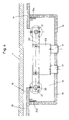
- Fig. 2 zeigt im Prinzip einen Schnitt nach II-II von Fig. 1,
- Fig. 3 ist in vergrößertem Maßstab mit weiteren Einzelheiten ein lotrechter Schnitt nach III-III von Fig. 2;
- Fig. 4 zeigt in einem noch größeren Maßstab einen Horizontalschnitt durch einen Installationsraum gemäß IV-IV von Fig. 3.
- Zunächst wird auf Fig. 1 und 2 Bezug genommen. Die Aufbauwand wird unmittelbar an einer Raumwand 1 hinter einem Krankenbett 2 aufgestellt, eine Montagearbeit, die mit herkömmlichen Mitteln von Schreinern ausgeführt werden kann. Die Einzelteile der Aufbauwand sind handelsübliche Elemente des Innenausbaus, so weit wie möglich vorgefertigt. Sie bestehen aus den bekannten Baustoffen der Möbelproduktion.
- Die Wand ruht auf einem Sockel 10, der bodenseitig aufgesetzt wird, wobei er an der Raumwand anliegt. Er wird in handwerklicher Weise (Schrauben, Dübel) befestigt. Seine Länge erstreckt sich über einen Mittelabschnitt 10a von einer Länge entsprechend der Breite des Krankenbettes 2. Daran schließen sich zwei etwas kürzere Seitenabschnitte 10b an, die seitlich gegenüber dem Krankenbett vorstehen.
- Auf diese Seitenabschnitte sind Bauelemente 15 mit Rechteckquerschnitt aufgesetzt. Sie umschließen einen Installationsraum 16, der zur Raumwand 1 hin offen ist, so daß die Möglichkeit besteht, Elektroleitungen und Gasleitungen von der Raumwand in den Installationsraum der Aufbauwand zu führen. An der Vorderseite des Kanalelementes 15 sind bereits fabrikatorisch Entnahmeelemente für die Intensivmedizin angebracht und zwar zwei Steckdosen 17 für Gas und darüber Bedienungelemente der elektrischen Einrichtungen wie Steckdosen, Schalter für Nachrichtenübermittlung, Starkstrom, Schwachstrom usw. Darüber ist auch eine Leuchte 19a für die Raumbeleuchtung eingebaut.
- Zwischen den Kanalelementen 15 ist die Raumwand 1 durch eine Platte 11 verkleidet. Sie ist mit den üblichen Mitteln (Dübel, Schrauben) fest mit der Raumwand 1 verbunden, wobei jedoch mit Hilfe von Abstandshaltern ein Raum 13 freigelassen ist, der ausreicht, um Leitungen aufzunehmen. Auch an beiden Seiten sind entsprechende Verkleidungsplatten 12 vorgesehen und in gleicher Weise befestigt.
- Den Entnahmeeinrichtungen für Gas und Strom bzw. für die Nachrichtenaufnahme an der Vorderseite des Kanalelementes 15 sind entsprechende Installationskästen 23, 24 zugeordnet. Sie befinden sich im Installationsraum 16 und sind jeweils an Querträgern 22 befestigt, die ihrerseits an zwei lotrecht aufgestellten Rohren höhenverstellbar gehalten sind. Jedes Rohr wird mit seinem unteren Ende von einer Büchse 20 aufgenommen mit einer Scheibe, die auf dem Sockel fest angebracht ist. Oben wird jedes Rohr von einer Halterung 24 gehalten, die eine feste Verbindung mit der Raumwand 1 herstellt.
- Der Zwischenraum zwischen den Verkleidungsplatten und den Kanalprofilen 15 einerseits und der Gebäudedecke andererseits wird durch ein Verkleidungselement 14, das gemäß Fig. 3 den Querschnitt eines Winkels haben kann, ausgefüllt. In handwerklicher Weise wird dieses Element bei der Montage zugeschnitten und befestigt.
- Wie man aus Fig. 4 erkennt, sind die Kanalelemente 15 durch Verbindungselemente mit den Verkleidungsplatten 11 und 12 gehalten. Diese Verbindungsmittel sind lösbar, im vorliegenden Fall Rastelemente 15a. Es besteht somit die Möglichkeit, jedes Kanalelement 15 abzunehmen, so daß der Installationsraum für die Wartung frei gemacht werden kann.
Claims (4)
- ein Sockel (10), der an einer Raumwand hinter einem Krankenbett aufstellbar ist, besitzt einen mittleren Abschnitt (10a), dessen Länge etwa der Breite eines Bettes entspricht, sowie am Bett überstehende seitliche Abschnitte (10b);
- auf jeden seitlichen Abschnitt ist ein Kanalelement (15) mit U-Querschnitt aufgestellt, das einen zur Raumwand hin offenen Installationsraum (16) umschließt und an dessen Vorderseite fabrikatorisch Entnahmeelemente (17, 18) für die Intensivmedizin angebracht sind;
- die den Entnahmeelementen zugeordneten Installationskästen (23, 24) sind jeweils an einem Querträger (22) befestigt, der seinerseits an zwei in einem Installationsraum lotrecht aufgestellten Rohren (21) höhenverstellbar gehalten ist;
- an der Raumwand sind mit einem Abstand, der die Aufnahme von Leitungen zuläßt, Verkleidungsplatten befestigt und zwar eine mittlere Verkleidungsplatte (11) zwischen den beiden Kanalprofilen (15) und zwei seitliche Verkleidungsplatten (12) seitlich neben den Kanalprofilen (15);
- die Kanalprofile (15) sind mit den Verkleidungsplatten (11, 12) lösbar verbunden;
- zur Abdeckung des Raumes zwischen den lotrechten Bauelementen und der Gebäudedecke ist eine obere Verkleidung (14) vorgesehen.
Applications Claiming Priority (2)
| Application Number | Priority Date | Filing Date | Title |
|---|---|---|---|
| DE3922634 | 1989-07-10 | ||
| DE3922634A DE3922634A1 (de) | 1989-07-10 | 1989-07-10 | Aufbauwand mit entnahmeeinrichtungen fuer die intensivmedizin |
Publications (3)
| Publication Number | Publication Date |
|---|---|
| EP0407652A2 true EP0407652A2 (de) | 1991-01-16 |
| EP0407652A3 EP0407652A3 (en) | 1992-03-18 |
| EP0407652B1 EP0407652B1 (de) | 1994-10-26 |
Family
ID=6384664
Family Applications (1)
| Application Number | Title | Priority Date | Filing Date |
|---|---|---|---|
| EP89117674A Expired - Lifetime EP0407652B1 (de) | 1989-07-10 | 1989-09-25 | Aufbauwand mit Entnahmeeinrichtungen für die Intensivmedizin |
Country Status (3)
| Country | Link |
|---|---|
| EP (1) | EP0407652B1 (de) |
| AT (1) | ATE113336T1 (de) |
| DE (1) | DE3922634A1 (de) |
Cited By (3)
| Publication number | Priority date | Publication date | Assignee | Title |
|---|---|---|---|---|
| DE19621888A1 (de) * | 1996-05-31 | 1997-12-04 | Harry C Dipl Ing Lieb | Installationselement |
| WO2008141610A1 (de) * | 2007-05-24 | 2008-11-27 | Voelker Manfred | Vormontagewand für praxiseinrichtung oder für intensivmedizinische oder stationäre krankenhausbettenräume |
| GB2451094A (en) * | 2007-07-17 | 2009-01-21 | Komfort Workspace Plc | A kit of parts for covering hospital equipment |
Families Citing this family (2)
| Publication number | Priority date | Publication date | Assignee | Title |
|---|---|---|---|---|
| DE29709652U1 (de) * | 1997-06-03 | 1998-10-01 | Trilux-Lenze Gmbh + Co Kg, 59759 Arnsberg | Versorgungseinheit für Krankenzimmer |
| DE10008433A1 (de) * | 2000-02-23 | 2001-09-06 | Krueger & Schuette Kerapid | Vorgefertigte Montage/Verkleidungselemente für Objekte und Einrichtungen, insbesondere in Sanitärbereichen |
Citations (3)
| Publication number | Priority date | Publication date | Assignee | Title |
|---|---|---|---|---|
| GB1232515A (de) * | 1969-05-16 | 1971-05-19 | ||
| EP0057169A1 (de) * | 1981-01-16 | 1982-08-04 | Johann Hinteregger | Vorgefertigter Installationsbauteil |
| FR2571768A1 (fr) * | 1984-04-03 | 1986-04-18 | Sermondadaz Jean | Element prefabrique constitutif d'une gaine technique d'un batiment |
Family Cites Families (2)
| Publication number | Priority date | Publication date | Assignee | Title |
|---|---|---|---|---|
| US3462892A (en) * | 1968-01-22 | 1969-08-26 | Ronald K Meyer | Adapter wall |
| FR2238816A1 (en) * | 1973-07-25 | 1975-02-21 | Leidinger Emil | Cupboard elements in hospital partition wall - as ready-to-install unit inserted in corresponding wall gap |
-
1989
- 1989-07-10 DE DE3922634A patent/DE3922634A1/de not_active Ceased
- 1989-09-25 AT AT89117674T patent/ATE113336T1/de not_active IP Right Cessation
- 1989-09-25 EP EP89117674A patent/EP0407652B1/de not_active Expired - Lifetime
Patent Citations (3)
| Publication number | Priority date | Publication date | Assignee | Title |
|---|---|---|---|---|
| GB1232515A (de) * | 1969-05-16 | 1971-05-19 | ||
| EP0057169A1 (de) * | 1981-01-16 | 1982-08-04 | Johann Hinteregger | Vorgefertigter Installationsbauteil |
| FR2571768A1 (fr) * | 1984-04-03 | 1986-04-18 | Sermondadaz Jean | Element prefabrique constitutif d'une gaine technique d'un batiment |
Cited By (4)
| Publication number | Priority date | Publication date | Assignee | Title |
|---|---|---|---|---|
| DE19621888A1 (de) * | 1996-05-31 | 1997-12-04 | Harry C Dipl Ing Lieb | Installationselement |
| WO2008141610A1 (de) * | 2007-05-24 | 2008-11-27 | Voelker Manfred | Vormontagewand für praxiseinrichtung oder für intensivmedizinische oder stationäre krankenhausbettenräume |
| GB2451094A (en) * | 2007-07-17 | 2009-01-21 | Komfort Workspace Plc | A kit of parts for covering hospital equipment |
| GB2451094B (en) * | 2007-07-17 | 2012-02-01 | Komfort Workspace Plc | A kit of parts for covering hospital equipment |
Also Published As
| Publication number | Publication date |
|---|---|
| DE3922634A1 (de) | 1991-01-17 |
| EP0407652B1 (de) | 1994-10-26 |
| ATE113336T1 (de) | 1994-11-15 |
| EP0407652A3 (en) | 1992-03-18 |
Similar Documents
| Publication | Publication Date | Title |
|---|---|---|
| DE69701988T2 (de) | Versetzbares trennwandsystem | |
| EP0643180B1 (de) | Profilleiste zur Befestigung von Spannbahnen und zum Hängen von Objekten | |
| EP2248504B1 (de) | Medizinische Versorgungseinheit mit Einbaumodulen | |
| EP0407652B1 (de) | Aufbauwand mit Entnahmeeinrichtungen für die Intensivmedizin | |
| DE19852927A1 (de) | Sicherheitsraum für informationstechnische Einrichtungen | |
| EP0735315A1 (de) | Elektrische Scherengitterleuchte | |
| EP1282929A1 (de) | Verkabelung eines modularen möbelsystems | |
| DE29617895U1 (de) | Versorgungsbalken für die Intensivpflege | |
| DE9108261U1 (de) | Wandhängendes Urinal | |
| DE29704549U1 (de) | Anordnung mit einer Installationswand aus Profilstangen, insbesondere Installationswand für Sanitärapparate | |
| DD296611A5 (de) | Aufbauwand mit entnahmeeinrichtungen fuer die intensivmedizin | |
| DE2721797B2 (de) | Elektrisches Installationssystem | |
| AT412520B (de) | Einrichtung zum installieren von versorgungsleitungen | |
| DE29909433U1 (de) | Schaltgeräteschrank | |
| DE2846948C2 (de) | Flächenkabelrost | |
| DE1764385B1 (de) | Beleuchtungsvorrichtung | |
| WO1993016246A1 (de) | Vorrichtung zur schalldämmung in räumen | |
| DE10165022B4 (de) | Einrichtung zum Installieren von Versorgungsleitungen | |
| DE9411771U1 (de) | Kabelführungseinrichtung | |
| EP1096629A1 (de) | Versorgungseinheit | |
| CH718847A2 (de) | Ausleger und Tragvorrichtung. | |
| DE9005855U1 (de) | Aufrichtbügel für Betten, insbesondere Kranken-, Pflege- oder Altenheimbetten | |
| DE7833011U1 (de) | Gestellanordnung mit einem Halterahmen | |
| DE1764385C (de) | Beleuchtungsvorrichtung | |
| EP0517938A1 (de) | Modulares Einrichtungssystem |
Legal Events
| Date | Code | Title | Description |
|---|---|---|---|
| PUAI | Public reference made under article 153(3) epc to a published international application that has entered the european phase |
Free format text: ORIGINAL CODE: 0009012 |
|
| AK | Designated contracting states |
Kind code of ref document: A2 Designated state(s): AT BE CH ES FR GB GR IT LI NL SE |
|
| PUAL | Search report despatched |
Free format text: ORIGINAL CODE: 0009013 |
|
| AK | Designated contracting states |
Kind code of ref document: A3 Designated state(s): AT BE CH ES FR GB GR IT LI NL SE |
|
| 17P | Request for examination filed |
Effective date: 19920427 |
|
| 17Q | First examination report despatched |
Effective date: 19930408 |
|
| GRAA | (expected) grant |
Free format text: ORIGINAL CODE: 0009210 |
|
| AK | Designated contracting states |
Kind code of ref document: B1 Designated state(s): AT BE CH ES FR GB GR IT LI NL SE |
|
| PG25 | Lapsed in a contracting state [announced via postgrant information from national office to epo] |
Ref country code: GR Free format text: LAPSE BECAUSE OF FAILURE TO SUBMIT A TRANSLATION OF THE DESCRIPTION OR TO PAY THE FEE WITHIN THE PRESCRIBED TIME-LIMIT Effective date: 19941026 Ref country code: BE Effective date: 19941026 Ref country code: FR Effective date: 19941026 Ref country code: GB Effective date: 19941026 Ref country code: ES Free format text: THE PATENT HAS BEEN ANNULLED BY A DECISION OF A NATIONAL AUTHORITY Effective date: 19941026 Ref country code: NL Effective date: 19941026 Ref country code: IT Free format text: LAPSE BECAUSE OF FAILURE TO SUBMIT A TRANSLATION OF THE DESCRIPTION OR TO PAY THE FEE WITHIN THE PRE;WARNING: LAPSES OF ITALIAN PATENTS WITH EFFECTIVE DATE BEFORE 2007 MAY HAVE OCCURRED AT ANY TIME BEFORE 2007. THE CORRECT EFFECTIVE DATE MAY BE DIFFERENT FROM THE ONE RECORDED.SCRIBED TIME-LIMIT Effective date: 19941026 |
|
| REF | Corresponds to: |
Ref document number: 113336 Country of ref document: AT Date of ref document: 19941115 Kind code of ref document: T |
|
| PG25 | Lapsed in a contracting state [announced via postgrant information from national office to epo] |
Ref country code: SE Effective date: 19950126 |
|
| EN | Fr: translation not filed | ||
| NLV1 | Nl: lapsed or annulled due to failure to fulfill the requirements of art. 29p and 29m of the patents act | ||
| GBV | Gb: ep patent (uk) treated as always having been void in accordance with gb section 77(7)/1977 [no translation filed] |
Effective date: 19941026 |
|
| PGFP | Annual fee paid to national office [announced via postgrant information from national office to epo] |
Ref country code: AT Payment date: 19950814 Year of fee payment: 7 Ref country code: CH Payment date: 19950814 Year of fee payment: 7 |
|
| PLBE | No opposition filed within time limit |
Free format text: ORIGINAL CODE: 0009261 |
|
| STAA | Information on the status of an ep patent application or granted ep patent |
Free format text: STATUS: NO OPPOSITION FILED WITHIN TIME LIMIT |
|
| 26N | No opposition filed | ||
| PG25 | Lapsed in a contracting state [announced via postgrant information from national office to epo] |
Ref country code: AT Effective date: 19960925 |
|
| PG25 | Lapsed in a contracting state [announced via postgrant information from national office to epo] |
Ref country code: CH Effective date: 19960930 Ref country code: LI Effective date: 19960930 |
|
| REG | Reference to a national code |
Ref country code: CH Ref legal event code: PL |